EP0025767A1 - Verfahren und Vorrichtung zum automatischen Prüfen eines digitalen Datenübertragungssystems - Google Patents
Verfahren und Vorrichtung zum automatischen Prüfen eines digitalen Datenübertragungssystems Download PDFInfo
- Publication number
- EP0025767A1 EP0025767A1 EP80401318A EP80401318A EP0025767A1 EP 0025767 A1 EP0025767 A1 EP 0025767A1 EP 80401318 A EP80401318 A EP 80401318A EP 80401318 A EP80401318 A EP 80401318A EP 0025767 A1 EP0025767 A1 EP 0025767A1
- Authority
- EP
- European Patent Office
- Prior art keywords
- modem
- test
- message
- transmission
- information
- Prior art date
- Legal status (The legal status is an assumption and is not a legal conclusion. Google has not performed a legal analysis and makes no representation as to the accuracy of the status listed.)
- Withdrawn
Links
Images

Classifications
-
- H—ELECTRICITY
- H04—ELECTRIC COMMUNICATION TECHNIQUE
- H04L—TRANSMISSION OF DIGITAL INFORMATION, e.g. TELEGRAPHIC COMMUNICATION
- H04L1/00—Arrangements for detecting or preventing errors in the information received
- H04L1/24—Testing correct operation
Definitions
- the present invention relates to the field of digital data transmissions and it relates more particularly to a method for automatic testing of a data transmission system, consisting of at least two modems and a transmission line.
- the invention also relates to a device ensuring the implementation of this method.
- a central data processing unit When it is desired to process information remotely, it is known to connect a central data processing unit to one or more peripheral organs for capturing and viewing this data, by a transmission channel, for example a telephone line. It is known to then use modulator devices for demodulating digital data, or modems, as the interface between the data transmission channel and the data processing units, at each end of the line.
- the generator and error counter which is a device distinct from the modem, which is connected to the latter and which makes it possible to pass over the links a specific sequence of signals; this sequence is either analyzed at the other end of the line by a second generator and error counter device, is returned on the same line by the modem located at the other end of this line, looped back on itself.
- This solution has various drawbacks, notably the cost of the test equipment, the lack of precision of the error diagnosis when only one test device is used, and the need to have qualified operators and two test devices. , one at each end of the link, when the source of errors must be located more precisely, that is to say when one wishes to know whether the errors come from the central modem, the peripheral modem or even the line of transmission itself.
- the subject of the present invention is a method performing automatically, from one of the ends of a link and by a single command, the successive test of the modem located at this end, of the modem located at the other end, and finally of the line itself, regardless of the operating mode of the link, without operator intervention at the other end.
- the test run is interrupted when a malfunction is detected, thus providing a precise diagnosis on the location of these faults.
- the different orders and information necessary for the tests or supplied by them are transmitted from one modem to another on a channel separate from that used for the transmission of the data, the channel, the speed of transmission and the form of the information being chosen in such a way that they remain usable in the event of malfunction of the various components of the system, thus enabling tests to be carried out under the conditions where they are most needed.
- the invention also relates to a device, integrated into modems, implementing this method.
- the method described in FIG. 1 begins with a step, referenced 1, of triggering a test between two modems, one of these modems being for example connected to a central data processing unit and the other modem being connected to a peripheral organs of a system which may include several. Any of the modems is chosen as the origin modem, from which the test is ordered and where the results are displayed, the other modem concerned by the test being called the end modem; other modems that the system may include are notified of the test in progress during this step.
- the test is triggered by the transmission by the modem origin of a specific form order to all the other modems in the system; the test is only triggered after receipt by the originating modem of a positive acknowledgment, or acknowledgment, sent by the end modem.
- the orders mentioned above can for example take the form of a series of bits made up of three parts: the first, on t bits, forms a message indicating that it is about an order and can be for example a sequence of t identical bits; the second part consists of the address of the end modem concerned, on u bits, and finally the third part on v bits, characterizes the order concerned.
- the order is preferably preceded by a flag constituted for example by a series of bits equal to 1, transmitted for a duration of the order of one second.
- the acquittal preferably has the same form as the order itself.
- test orders are issued on a channel different from that which is used by the data themselves.
- This channel is preferably located at the bottom of the bandwidth of the modems and the information exchanges take place there at very low speed, of the order of ten Bauds, so that the test information is disturbed as a minimum by poor quality of the link.
- Step 20 consists in disconnecting the original modem from the transmission line and looping this modem over on itself, so as to allow the test of its proper functioning.
- the next step (21) is made necessary when, as mentioned above, the test procedures take place on a channel separate from the data channel: it consists in testing the operation of the control channel of the original modem. This test is carried out using a set of circuits described in Figure 2. If the operation of this control channel is not correct, the corresponding information is displayed (step 23) and causes the flow to stop. of the test.
- a time delay device determines whether or not the test should be repeated (step 22); this time delay can be done for example by counting the number of bits transmitted to test the control channel; for example, the operation of the control channel can be considered correct if no error is detected on 10 000 test bits, which corresponds, for a frequency of 2400 Hz, to a duration of approximately 4 sec.
- test 22 determines whether the duration chosen for test 21 is reached (or if the number of test bits is reached), it is the modulator-demodulator function of the original modem, on the channel borrowed by the data, which is tested (step 24). For this test, in the same way, when an operating fault is detected, the corresponding information is displayed (step 26) and causes the test to stop running. When, on the contrary, no error is detected, the test is repeated as many times as necessary to have a good probability of correct operation. As before, when the predefined number of iterations is reached (test 25), we go to the next step (27), which is reconnecting the original modem to the transmission line, marking the end of the test of the latter. .
- steps (30 to 41) relate to the end-loop closed loop test.
- This test begins with the looping (step 30) of this modem, that is to say its disconnection from the line, with reconnection controlled by itself, at the end of the test.
- step 31 the test of the control channel of the end modem is then carried out (step 31). Contrary to what has been said previously, the detection of an error indicates here that either the control channel or the transmission line is defective. This defect is displayed (step 35) on the end modem under test. In the event that no error is detected, the test is resumed as before after passing through a timeout (or counting) step 32. When the desired number of bits is reached, the end modem reconnects to the line and issues (step 33) a message of good functioning intended for the origin modem. If the original modem does not receive such a message, it displays information indicating a malfunction which is therefore either at the end modem or at the line level. As before, this error stops the flow of the process.
- a second time-out step (34) making it possible to repeat the process 31, 32, 33 which has just been described a number of times. For example, if the same value is chosen for the counting step 34 as for steps 22 or 25, namely 10,000 bits, the timing of step 32 can then correspond to the counting of 2,000 bits, which leads to the emission of five messages of good functioning.
- step 36 After the test of the end modem control channel, the test (step 36) of the modulation-demodulation function on the data channel takes place, similar to step 24.
- the detection of a malfunction causes the display (step 40) of the corresponding information and stops the running of the test.
- step 40 the correct functioning of the modem after time-out (37 and 39) and information from the original modem (38) steps, similar to steps 32, 34 and 33 respectively described above, leads to the unwinding of the end modem ( step 41) and at the end of the test thereof.
- half duplex or alternat or half duplex means an operating mode in which the modems use their transmission line one after the other, and by "full duplex", or full duplex , an operation in which the modems can use the line at the same time, this being made possible either by the allocation to the information of bands of fre quence different according to their direction of travel, or by a splitting of the electrical connections.
- step 50 as in the rest of the method, the same principle is retained, namely the command of all the tests by the modem chosen as the origin; as, moreover, especially in the case of a multipoint network, the two modems concerned may not be in the same operating state, it is frequent that the modem connected to the central unit operates in "full duplex” then that a certain number of modems connected to peripheral units operate in "half duplex". ; in the latter case, the test procedure must take place in "half duplex".
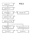
- This next step (51) consists in testing the link itself, in "half duplex” or “full duplex” mode according to what has been determined previously. An embodiment of this test is given in FIG. 3.
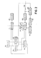
- FIG. 2 represents an embodiment of the device according to the invention.
- This device comprises at least two modems connected by a data transmission channel, constituted for example by a telephone line.
- a data transmission channel constituted for example by a telephone line.
- the modems namely its modulator-demodulator part (11), its associated electronic circuits (61 to 71) which ensure the implementation of the method described above, and the transmission line (120) are represented.
- the modem situated at the other end of the line is identical to that which is represented, in order to satisfy one of the basic principles of the present invention, namely the trivialization of modems.
- the method according to the invention begins with the triggering of the test by a command supplied to a sequencer 71, which has the function of the timed triggering of the three tests described above and the command accordingly of the various circuits of the device.
- the sequencer 71 is connected to a display device 67 which indicates which of the tests is in progress at all times.
- the modulator-demodulator circuit 11 of the modem is connected to a control element 61 for bringing the original modem into contact with another modem on the network.
- the next step in the process of Figure 1 is the test of the original modem. This takes place in two stages: first the test of the control channel (step 21), then the test of the modulation-demodulation function of the data channel (step 24). In one embodiment, these two tests can " take place in the same way, using a set of four circuits 62, 63, 64 and 65, and a signal generator 66: the sequencer 71 controls to the generator 66 the transmission of a determined message, preferably consisting of a series of bits of the same value, which is modulated by the circuit 11 and directed towards an attenuation line 63, which has the function of imposing on the signal the maximum attenuation compatible with the proper functioning of the modem.
- Circuit 65 is a circuit switch controlled by the sequencer 71, making it possible to connect the modem 11 to the attenuation line 63 during this test.
- This attenuated signal is then received by the demodulator part of the circuit 11 and sent to a comparator 68, controlled by the sequencer 71, which has the function of comparing the message demodulated by the circuit 11 with the message supplied by the generator 66, and kept in a memory element belonging for example to the comparator 68. If the latter finds a sufficient identity, it sends a message of correct operation to the sequencer 71, which allows to go to the next step of the test.
- a display device 70 which may or may not be separate from the device 67, as well as to the sequencer 71, in order to cause the process to stop.
- a scrambler-scrambler device 62 of pseudo-random type which has the function of scrambling the signal transmitted by the modem of a known manner, which corresponds to a self-synchronizing jammer-descrambler device 64.
- the insertion of interference into a transmission system makes it possible to use test messages that are simple to generate and recognize, without therefore being placed in transmission conditions that are too favorable.
- the test can consist simply in verifying that, when a finite series of bits of the same value are emitted, one effectively obtains after modulation and demodulation the presence of the two states, zero and one of the signal.
- the comparator 68 when the comparator 68 does not detects no error in this step, it transmits a signal to the sequencer 71 which allows it to pass to the next test, namely the test of the end modem.
- this step is broken down into testing the control channel itself and then testing the data channel; this stage proceeds in the same way, with one exception which concerns the information of the modem which is the source of a possible operational failure.
- the modem illustrated in FIG. 2 is the end modem. It therefore receives via the link 120 a test message ordering it to loop back on itself (step 30 of FIG. 1), then the test successively of the control channel and of the data channel.
- the test of the data channel is described below.
- the original modem then sends a test message preferably made up as above of a set of bits of the same value transmitted by the channel 120, possibly and for the same reasons as before, via two jammer-unscrambler devices such as 62.
- the modem 11 transmits the message to the comparator 68, which determines whether or not the received message is identical to the test message. As before, this operation is repeated a certain number of times, the iterations being for example counted by a counter 69, controlled by the sequencer 71. After a certain number of iterations showing correct operation, it is sent to the modem originates a message indicating that there is no error at the end modem.
- the total duration of the test is of the order of 10 4 bits
- the duration of the iteration in question here is 2000 bits
- the original modem must receive 5 messages of correct operation. The absence of one of these messages is reflected in the originating modem by a signal intended for the display device 70 and the sequencer 71 for stopping the process.
- the counter 69 of the original modem sends a message to the sequencer 71 of this same original modem, the sequencer ordering the next step, namely the unwinding of the end modem (step 41 in FIG. 1) then launching of the link test itself by the step, 50 (FIG. 1) of the choice of the connection mode described above, and finally the test of the connection itself (step 51 in FIG. 1), one embodiment of which is described in FIG. 3, in relation to figure 2.
- the first step of the method described in FIG. 3, carried out immediately after the choice of the transmission mode "half" or “full duplex", is illustrated by a block 12 in the figure. It consists of the transmission of a predefined message, called T, by the modem chosen as the origin of the test. Referring to FIG. 2, it can be seen that this transmission is carried out by the generator 66 on command from the sequencer 71, the form of the message T possibly being for example stored in a memory element belonging to the sequencer 71.
- the next step, marked 13 in the figure, consists in receiving the message T by the end modem; this received message is called T and, depending on whether the transmission was carried out with or without error, it is or is not identical to T.
- the next step, marked 14 in the figure, consists for the end modem in carrying out the comparison of the message T 'which it has received with the message T which has been sent, by means of the comparator 68 of FIG. 2.
- the modem in deduces the existence or non-existence of a transmission error in the direction from the origin modem to the end modem, that is to say a forward error. This information is called E a .
- this information E is displayed (step 15) on the display 70 of the end modem.
- the end modem sends a message to the originating modem containing the previous message T accompanied by a message representing the error E (step 16).
- the comparator output information is directed on the one hand to the sequencer 71 so that it supplies the signal T to the generator 66 and, on the other hand, to the generator 66 for the transmission of the message representing E.
- the information displayed is also directed to the sequencer 71 to indicate the end of the test.
- a forward transmission error results in the transmission by the modem end of M bits of value opposite to that of the signal T, namely M bits equal to zero in the example above; analogously to what is said above, when the comparator 68 of the original modem detects an error, the counter 69 counts the number b and if b is greater than M / 2, we deduce that it s is a go error.
Applications Claiming Priority (2)
| Application Number | Priority Date | Filing Date | Title |
|---|---|---|---|
| FR7923246 | 1979-09-18 | ||
| FR7923246A FR2466143A1 (fr) | 1979-09-18 | 1979-09-18 | Procede et dispositif de test automatique d'un systeme de transmission de donnees numeriques |
Publications (1)
| Publication Number | Publication Date |
|---|---|
| EP0025767A1 true EP0025767A1 (de) | 1981-03-25 |
Family
ID=9229756
Family Applications (1)
| Application Number | Title | Priority Date | Filing Date |
|---|---|---|---|
| EP80401318A Withdrawn EP0025767A1 (de) | 1979-09-18 | 1980-09-16 | Verfahren und Vorrichtung zum automatischen Prüfen eines digitalen Datenübertragungssystems |
Country Status (2)
| Country | Link |
|---|---|
| EP (1) | EP0025767A1 (de) |
| FR (1) | FR2466143A1 (de) |
Cited By (10)
| Publication number | Priority date | Publication date | Assignee | Title |
|---|---|---|---|---|
| EP0380730A1 (de) * | 1989-02-02 | 1990-08-08 | Siemens Aktiengesellschaft | Verfahren und Schaltungsanordnung zur Überprüfung der Funktionsfähigkeit eines Datenübertragungsweges |
| WO2001056200A1 (en) * | 2000-01-26 | 2001-08-02 | Vyyo, Ltd. | A unidirectional communication scheme for remote maintenance and co ntrol in a broadband wireless access system |
| US6498821B2 (en) | 2000-01-26 | 2002-12-24 | Vyyo, Ltd. | Space diversity method and system for broadband wireless access |
| US6856786B2 (en) | 2000-01-26 | 2005-02-15 | Vyyo Ltd. | Quality of service scheduling scheme for a broadband wireless access system |
| US6941119B2 (en) | 2000-01-26 | 2005-09-06 | Vyyo Ltd. | Redundancy scheme for the radio frequency front end of a broadband wireless hub |
| US6987754B2 (en) | 2000-03-07 | 2006-01-17 | Menashe Shahar | Adaptive downstream modulation scheme for broadband wireless access systems |
| US7123650B2 (en) | 2000-01-26 | 2006-10-17 | Vyyo, Inc. | Offset carrier frequency correction in a two-way broadband wireless access system |
| US7149188B2 (en) | 2000-01-26 | 2006-12-12 | Vyyo, Inc. | Distributed processing for optimal QOS in a broadband access system |
| US7298715B2 (en) | 2000-03-14 | 2007-11-20 | Vyyo Ltd | Communication receiver with signal processing for beam forming and antenna diversity |
| US7359434B2 (en) | 2000-01-26 | 2008-04-15 | Vyyo Ltd. | Programmable PHY for broadband wireless access systems |
Citations (5)
| Publication number | Priority date | Publication date | Assignee | Title |
|---|---|---|---|---|
| US3786187A (en) * | 1971-03-23 | 1974-01-15 | Alitalia Spa | Apparatus for testing systems and data transmitting networks by simulation |
| FR2317829A1 (fr) * | 1975-07-09 | 1977-02-04 | Siemens Ag | Procede de verification automatique de la capacite de fonctionnement de systeme de transmission de donnees |
| US4039751A (en) * | 1972-04-24 | 1977-08-02 | General Datacomm Industries, Inc. | Method and apparatus for closed loop testing of first and second modulators and demodulators |
| DE2824578A1 (de) * | 1977-06-06 | 1979-01-11 | Milgo Electronic Corp | Einrichtung zur fehlererkennung in datenmodems und zugehoerigen schaltungen |
| FR2404970A1 (fr) * | 1977-10-03 | 1979-04-27 | Sfena | Systeme de couplage pour transmission en duplex de donnees numeriques entre deux unites de traitement |
-
1979
- 1979-09-18 FR FR7923246A patent/FR2466143A1/fr active Granted
-
1980
- 1980-09-16 EP EP80401318A patent/EP0025767A1/de not_active Withdrawn
Patent Citations (5)
| Publication number | Priority date | Publication date | Assignee | Title |
|---|---|---|---|---|
| US3786187A (en) * | 1971-03-23 | 1974-01-15 | Alitalia Spa | Apparatus for testing systems and data transmitting networks by simulation |
| US4039751A (en) * | 1972-04-24 | 1977-08-02 | General Datacomm Industries, Inc. | Method and apparatus for closed loop testing of first and second modulators and demodulators |
| FR2317829A1 (fr) * | 1975-07-09 | 1977-02-04 | Siemens Ag | Procede de verification automatique de la capacite de fonctionnement de systeme de transmission de donnees |
| DE2824578A1 (de) * | 1977-06-06 | 1979-01-11 | Milgo Electronic Corp | Einrichtung zur fehlererkennung in datenmodems und zugehoerigen schaltungen |
| FR2404970A1 (fr) * | 1977-10-03 | 1979-04-27 | Sfena | Systeme de couplage pour transmission en duplex de donnees numeriques entre deux unites de traitement |
Cited By (10)
| Publication number | Priority date | Publication date | Assignee | Title |
|---|---|---|---|---|
| EP0380730A1 (de) * | 1989-02-02 | 1990-08-08 | Siemens Aktiengesellschaft | Verfahren und Schaltungsanordnung zur Überprüfung der Funktionsfähigkeit eines Datenübertragungsweges |
| WO2001056200A1 (en) * | 2000-01-26 | 2001-08-02 | Vyyo, Ltd. | A unidirectional communication scheme for remote maintenance and co ntrol in a broadband wireless access system |
| US6498821B2 (en) | 2000-01-26 | 2002-12-24 | Vyyo, Ltd. | Space diversity method and system for broadband wireless access |
| US6856786B2 (en) | 2000-01-26 | 2005-02-15 | Vyyo Ltd. | Quality of service scheduling scheme for a broadband wireless access system |
| US6941119B2 (en) | 2000-01-26 | 2005-09-06 | Vyyo Ltd. | Redundancy scheme for the radio frequency front end of a broadband wireless hub |
| US7123650B2 (en) | 2000-01-26 | 2006-10-17 | Vyyo, Inc. | Offset carrier frequency correction in a two-way broadband wireless access system |
| US7149188B2 (en) | 2000-01-26 | 2006-12-12 | Vyyo, Inc. | Distributed processing for optimal QOS in a broadband access system |
| US7359434B2 (en) | 2000-01-26 | 2008-04-15 | Vyyo Ltd. | Programmable PHY for broadband wireless access systems |
| US6987754B2 (en) | 2000-03-07 | 2006-01-17 | Menashe Shahar | Adaptive downstream modulation scheme for broadband wireless access systems |
| US7298715B2 (en) | 2000-03-14 | 2007-11-20 | Vyyo Ltd | Communication receiver with signal processing for beam forming and antenna diversity |
Also Published As
| Publication number | Publication date |
|---|---|
| FR2466143A1 (fr) | 1981-03-27 |
| FR2466143B1 (de) | 1984-05-04 |
Similar Documents
| Publication | Publication Date | Title |
|---|---|---|
| EP0026135B1 (de) | Verfahren zum Prüfen einer Digitaldatenübertragungsleitung zwischen zwei Modems und Vorrichtung zur Durchführung dieses Verfahrens | |
| EP0699997B1 (de) | Verfahren zur Fehleridentifizierung in einem komplexen System | |
| EP0003493B1 (de) | Datenübertragungssystem zwischen Stationen die in einer Schleife miteinander verbunden sind | |
| FR2674390A1 (fr) | Dispositif de transmission d'informations numeriques sur une ligne d'un reseau d'energie electrique. | |
| FR2622756A1 (fr) | Systeme de communication bidirectionnelle par cables | |
| EP0025767A1 (de) | Verfahren und Vorrichtung zum automatischen Prüfen eines digitalen Datenübertragungssystems | |
| EP0032327A2 (de) | Verfahren und Anlage zur Sicherung eines digitalen Übertragungskabels | |
| FR2519820A1 (fr) | Multiplexeur demultiplexeur asynchrome numerique temporel | |
| FR2680067A1 (fr) | Procede de controle d'un repartiteur de lignes; cable auxiliaire, connecteur et repartiteur pour la mise en óoeuvre de ce procede. | |
| FR2504330A1 (fr) | Reseau local de communication decentralise | |
| CA2040941C (fr) | Procede et dispositif de retour a une liaison normale apres utilisation d'une liaison de secours dans un systeme de transmission de donnees | |
| CA2002682C (fr) | Systeme d'echange de messages en temps reel entre stations reliees par une liaison en boucle, notamment entre stations d'un central de telecommunications | |
| FR2731863A1 (fr) | Reseau cable de television avec voie montante | |
| FR2462715A1 (fr) | Systeme de localisation de defaut pour circuit de transmission bidirectionnelle simultanee a repeteurs | |
| FR2492197A1 (fr) | Systeme de diagnostic pour un reseau de modems | |
| FR3012617A1 (fr) | Methode de localisation de defauts electriques au sein d'un reseau de lignes de transmission et systeme associe | |
| FR2741220A1 (fr) | Systeme de surveillance et de gestion d'un reseau d'acces point-multipoint | |
| FR2462065A1 (fr) | Dispositif de commutation automatique d'equipements de transmission de signaux numeriques et faisceaux hertziens comportant un tel dispositif | |
| CH645223A5 (fr) | Dispositif de controle des communications dans un reseau de transmission en duplex. | |
| FR2691029A1 (fr) | Procédé d'analyse à distance de données d'un protocole, terminal d'abonné spécialisé et dispositif d'analyse distant correspondant. | |
| EP0011014A1 (de) | Vorrichtung zur Messung der Qualität einer digitalen Verbindungsstrecke und eine solche Vorrichtung enthaltende Übertragungseinrichtungen | |
| EP0770286B1 (de) | Verfahren und vorrichtung zur übertragung zwischen einer vielzahl von an unterschiedlichen elektrischen versorgungsnetzen angeschlossenen lokalen einheiten | |
| EP0651534A1 (de) | Digitale Vorrichtung zum Verbinden eine Mehrzahl von Rechnerarbeitsplätzen an ein lokales Ringnetz | |
| EP0133139A1 (de) | Hilfsgerät zum Betrieb von Datenübertragungssystemen auf lokalen Netzen und Systeme, die ein solches Gerät enthalten | |
| FR2505110A1 (en) | Redundant digital information transmission system - uses six frequency pulses in coded sequence to be received within time windows in order to reduce possibility of noise interference |
Legal Events
| Date | Code | Title | Description |
|---|---|---|---|
| PUAI | Public reference made under article 153(3) epc to a published international application that has entered the european phase |
Free format text: ORIGINAL CODE: 0009012 |
|
| AK | Designated contracting states |
Designated state(s): BE DE GB IT NL |
|
| STAA | Information on the status of an ep patent application or granted ep patent |
Free format text: STATUS: THE APPLICATION HAS BEEN WITHDRAWN |
|
| 18W | Application withdrawn |
Withdrawal date: 19810902 |
|
| RIN1 | Information on inventor provided before grant (corrected) |
Inventor name: GREGOIRE, MICHEL Inventor name: VUILLEMIN, JEAN-CLAUDE |