EP0024990B1 - Ensemble de traversée de dalle de confinement pour transfert de combustible nucléaire irradié - Google Patents
Ensemble de traversée de dalle de confinement pour transfert de combustible nucléaire irradié Download PDFInfo
- Publication number
- EP0024990B1 EP0024990B1 EP80401217A EP80401217A EP0024990B1 EP 0024990 B1 EP0024990 B1 EP 0024990B1 EP 80401217 A EP80401217 A EP 80401217A EP 80401217 A EP80401217 A EP 80401217A EP 0024990 B1 EP0024990 B1 EP 0024990B1
- Authority
- EP
- European Patent Office
- Prior art keywords
- cover plate
- ramp
- heat pipes
- heat
- assembly according
- Prior art date
- Legal status (The legal status is an assumption and is not a legal conclusion. Google has not performed a legal analysis and makes no representation as to the accuracy of the status listed.)
- Expired
Links
- 239000003758 nuclear fuel Substances 0.000 title claims description 7
- 239000000446 fuel Substances 0.000 claims description 15
- 239000012809 cooling fluid Substances 0.000 claims description 11
- 239000013529 heat transfer fluid Substances 0.000 claims description 10
- 238000001816 cooling Methods 0.000 claims description 7
- QSHDDOUJBYECFT-UHFFFAOYSA-N mercury Chemical compound [Hg] QSHDDOUJBYECFT-UHFFFAOYSA-N 0.000 claims description 4
- 229910052753 mercury Inorganic materials 0.000 claims description 4
- 238000006073 displacement reaction Methods 0.000 claims description 2
- 230000004907 flux Effects 0.000 claims 2
- 230000000712 assembly Effects 0.000 description 8
- 238000000429 assembly Methods 0.000 description 8
- XKRFYHLGVUSROY-UHFFFAOYSA-N Argon Chemical compound [Ar] XKRFYHLGVUSROY-UHFFFAOYSA-N 0.000 description 4
- 238000009434 installation Methods 0.000 description 4
- 239000007788 liquid Substances 0.000 description 4
- 238000000034 method Methods 0.000 description 3
- DGAQECJNVWCQMB-PUAWFVPOSA-M Ilexoside XXIX Chemical compound C[C@@H]1CC[C@@]2(CC[C@@]3(C(=CC[C@H]4[C@]3(CC[C@@H]5[C@@]4(CC[C@@H](C5(C)C)OS(=O)(=O)[O-])C)C)[C@@H]2[C@]1(C)O)C)C(=O)O[C@H]6[C@@H]([C@H]([C@@H]([C@H](O6)CO)O)O)O.[Na+] DGAQECJNVWCQMB-PUAWFVPOSA-M 0.000 description 2
- 229910052786 argon Inorganic materials 0.000 description 2
- 230000005494 condensation Effects 0.000 description 2
- 238000009833 condensation Methods 0.000 description 2
- 239000002826 coolant Substances 0.000 description 2
- 238000007599 discharging Methods 0.000 description 2
- 238000001704 evaporation Methods 0.000 description 2
- 230000008020 evaporation Effects 0.000 description 2
- 239000007789 gas Substances 0.000 description 2
- 238000007689 inspection Methods 0.000 description 2
- 239000007791 liquid phase Substances 0.000 description 2
- 238000012423 maintenance Methods 0.000 description 2
- 229910052708 sodium Inorganic materials 0.000 description 2
- 239000011734 sodium Substances 0.000 description 2
- 238000009423 ventilation Methods 0.000 description 2
- 230000001143 conditioned effect Effects 0.000 description 1
- 230000000694 effects Effects 0.000 description 1
- 230000008030 elimination Effects 0.000 description 1
- 238000003379 elimination reaction Methods 0.000 description 1
- 238000005516 engineering process Methods 0.000 description 1
- 230000003628 erosive effect Effects 0.000 description 1
- 239000012530 fluid Substances 0.000 description 1
- 238000010438 heat treatment Methods 0.000 description 1
- 239000011261 inert gas Substances 0.000 description 1
- 229910001338 liquidmetal Inorganic materials 0.000 description 1
- 238000004519 manufacturing process Methods 0.000 description 1
- 229910052751 metal Inorganic materials 0.000 description 1
- 239000002184 metal Substances 0.000 description 1
- 239000012071 phase Substances 0.000 description 1
- 238000012958 reprocessing Methods 0.000 description 1
- 239000012808 vapor phase Substances 0.000 description 1
Images


Classifications
-
- G—PHYSICS
- G21—NUCLEAR PHYSICS; NUCLEAR ENGINEERING
- G21C—NUCLEAR REACTORS
- G21C19/00—Arrangements for treating, for handling, or for facilitating the handling of, fuel or other materials which are used within the reactor, e.g. within its pressure vessel
- G21C19/20—Arrangements for introducing objects into the pressure vessel; Arrangements for handling objects within the pressure vessel; Arrangements for removing objects from the pressure vessel
-
- Y—GENERAL TAGGING OF NEW TECHNOLOGICAL DEVELOPMENTS; GENERAL TAGGING OF CROSS-SECTIONAL TECHNOLOGIES SPANNING OVER SEVERAL SECTIONS OF THE IPC; TECHNICAL SUBJECTS COVERED BY FORMER USPC CROSS-REFERENCE ART COLLECTIONS [XRACs] AND DIGESTS
- Y02—TECHNOLOGIES OR APPLICATIONS FOR MITIGATION OR ADAPTATION AGAINST CLIMATE CHANGE
- Y02E—REDUCTION OF GREENHOUSE GAS [GHG] EMISSIONS, RELATED TO ENERGY GENERATION, TRANSMISSION OR DISTRIBUTION
- Y02E30/00—Energy generation of nuclear origin
- Y02E30/30—Nuclear fission reactors
Definitions
- the invention relates to a containment slab crossing assembly for the transfer of irradiated nuclear fuel, in particular between the vessel containing the core of a fast neutron nuclear reactor and an irradiated nuclear fuel storage area located outside the tank.
- the fuel is generally placed inside sheathed needles arranged in a bundle in elongated housings constituting assemblies provided with a gripping head allowing their handling.
- the irradiated assembly is extracted from the core by means of a gripping grapple and transferred to a pot.
- handling placed at the periphery of the core, at the base of an inclined guide ramp allowing the irradiated assembly to be conveyed to a pivoting hood placed above the slab of the reactor vessel.
- a second inclined guide ramp which opens into the pivoting hood, makes it possible to route the irradiated assembly into an external storage receptacle adjoining the reactor cover and closed by a slab extending the slab of the reactor vessel.
- the irradiated assembly is then extracted from the handling pot and placed in a cell where it loses part of its activity, before being introduced into a sealed case and enclosed in an armored castle allowing it to be transported to a recycling center. reprocessing.
- French patent FR-A-2,235,462 has been proposed, filed on June 27, 1973 in the name of the French Atomic Energy Commission for the "Process for handling irradiated fuel assemblies in a fast neutron reactor and installation for the implementation of this process ", to transfer the irradiated assembly in the external storage receptacle to the reactor vessel as soon as this assembly is extracted from the core, the handling pot in which the assembly is placed during of its transport being arranged so as to evacuate the calories released by this assembly.
- the subject of the present invention is the production of a set of bushings for these slabs allowing the residual power of the irradiated assembly contained in the handling pot to be removed, even in the event of the latter being accidentally blocked at the bushing. of a slab.
- a set of crossing of a containment slab for transfer of irradiated nuclear fuel comprising a ferrule for crossing secured to the slab and a guide ramp crossing the ferrule and in which moves a handling pot carrying the fuel, said assembly being characterized in that it further comprises a device for removing the residual heat dissipated by the fuel, this device comprising a bundle of heat pipes arranged parallel to the ramp over a length at least equal to that of the shell and of the means for discharging the heat flow conveyed above the slab by the heat pipes.
- the means for discharging the heat flow conveyed over the slab by the heat pipes comprise an annular grille in which circulates a cooling fluid, the bundle of heat pipes extending at the inside said grille.
- the part of each of the heat pipes arranged inside the shell preferably comprises cooling fins.
- a helical baffle may be disposed in the shell between an inlet port and an outlet port for the coolant to improve the circulation of the coolant inside the grille.
- the heat pipes are arranged in the annular space defined between the ferrule and the ramp.
- the heat pipes are then distributed around the ramp opposite the lights formed therein.
- the device for removing the residual heat dissipated by the fuel and the guide rail can be dismantled independently of one another, which makes inspection and maintenance of the various parts of the assembly impossible. crossing.
- the heat pipes are arranged inside the guide ramp, on either side of the handling pot.
- the part of the ramp arranged inside the grille can then be provided at least one removable element, the device for removing the residual heat dissipated by the fuel being removable after removal of said element, and the guide ramp being removable after removal of this device.
- means are provided for ensuring the radial positioning of the heat pipes relative to the ramp while allowing their relative displacement in a direction parallel to the area of the ramp. This characteristic makes it possible to take account of differential expansions and allows the disassembly of the different parts of the assembly.
- the heat transfer fluid contained in the heat pipes is mercury.
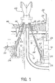
- the reference 10 designates a thick-walled enclosure, generally made of concrete, internally delimiting an open cavity of generally cylindrical shape with a vertical axis, in which the vessel 12 of a fast neutron nuclear reactor is mounted.
- the core 14 of this reactor, placed inside the tank 12 is immersed in a liquid cooling metal 16, such as sodium, surmounted by a layer 18 of an inert gas such as argon.
- the upper part of the cover 12 is suspended from a horizontal slab 20 closing off the enclosure 10.
- the slab 20 has different passage openings allowing access to the interior of the incubator, and in particular a circular opening in which is mounted an assembly consisting of two rotating plugs 22 and 24 eccentric relative to each other of in such a way that the combined rotations of these two plugs allow a handling member 26 passing through the plug 24 to be positioned vertically from any point of the heart 14.
- the member 26 has at its lower end located in the tank 12 a gripping grapple 28 capable of coming to grip the handling head 32 of each of the assemblies 30 which constitute the core 14.
- Each assembly 30 is formed of an outer casing containing a bundle of sheathed needles containing the nuclear fuel, and it is arranged vertically in the core 14.
- the grapple 28 makes it possible to extract each assembly from the reactor core and to transfer it to a handling pot 34 disposed at the periphery of the core, while maintaining it in the liquid sodium 16 contained in the tank.
- the handling pot 34 is capable of moving on an inclined guide ramp 36 plunging inside the tank 12 and passing through the closing slab 20 by a crossing assembly 38, different variants of which will be described in more detail below. with reference to FIGS. 2 to 6.
- the pot 34 produced for example in accordance with the provisions described and claimed in French patent FR-A-2,379,139 filed on January 26, 1977 in the name of the Commissariat à l'Energie Atomique pour »pot handling a fuel assembly ", is brought into the axis of the ramp 36 by means of a yoke system 40.
- the irradiated assembly 30 placed in the pot 34 is moved along the inclined ramp 36 through the bushing assembly 38 to be brought out of the tank 12 and inside a pivoting hood 42, for example by means of a winch (not shown).
- the pivoting hood 42 is produced for example in accordance with the provisions described and claimed in French patent FR-A-2 188 251 filed on June 8, 1972 in the name of the Atomic Energy Commission for "transfer hood".
- the pivoting hood 42 is equipped with a ventilation circuit making it possible to remove the residual power from the irradiated assembly when it is inside the hood.
- the pivoting hood 42 is designed to impart a 180 ° rotation to the handling pot containing the fuel assembly allowing it to be brought opposite a second inclined ramp 44.
- the ramp 44 passes through, by means of a bushing assembly 46 which may be identical to the bushing assembly 38, a slab 48 closing a storage receptacle 50 contiguous to the vessel 12 of the reactor, such that the slab 48 is arranged in the extension of the slab 20.
- the storage receptacle 50 is filled with liquid metal, and it contains a rotating barrel (not shown) intended to receive the irradiated assembly 30 after it has been extracted from the handling pot 34 by means of a handling member equipped with a grapple (not shown) of the same type as the 26 and the grapple 28.
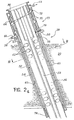
- the crossing assembly 38 of the containment slab 20 of the reactor vessel comprises a crossing ferrule 52 integral with the slab 20 and in which a thermal fur 54 carried is disposed by the ferrule 52 and spaced therefrom so as to define an annular space communicating with the reactor vessel.
- the ferrule 52 and the liner 54 form a flange 55 above the slab 20 on which a bearing surface 56 is provided.
- the ferrule 52 and the sleeve 54 define in the slab 20 a passage which the guide ramp 36 freely crosses, the latter being provided in a plane normal to the section plane of FIG. 2a with two guide rails 58 on which come to roll rollers (not shown) which can be mounted either on a carriage carrying the handling pot 34, or directly on the latter.
- a bundle of heat pipes 60 is disposed in the annular space defined between the fur 54 and the ramp 36 parallel to the axis of that - Here and over the entire length of the shell 52. More specifically, and as illustrated in particular in FIG. 3, the heat pipes 60 are arranged in four groups regularly distributed around the ramp 36 opposite the lights 62 formed in the latter , in order to allow most of the heat dissipated by an irradiated assembly accidentally blocked in the shell 52 to reach the heat pipes 60.
- the heat pipes 60 extend upwards beyond the shell 52 inside an annular grille 64 in which a cooling fluid such as air circulates between an orifice d 'lower inlet 66 and an upper outlet orifice 68.
- the annular grille 64 thus makes it possible to evacuate the heat flow conveyed above the slab 20 by the heat pipes 60.
- the part of each of heat pipes disposed inside the calender comprises radial cooling fins 70.
- the circulation of the cooling fluid between the inlet orifice 66 and the outlet orifice 68 is improved by the presence of a helical baffle 72 inside the calender 64.
- the circulation of the cooling fluid inside the calender 64 between the inlet orifice 66 and outlet 68 may come from either from a pressure circuit connected in parallel to the ventilation circuit of the pivoting hood 42, or from natural convection, the calender 64 then being connected to the depression created by a chimney. In both cases, this circulation can be controlled by operating two flaps (not shown) located respectively at the inlet 66 and outlet 68 ports.
- each of the heat pipes 60 is closed and filled with a heat transfer fluid which is in the liquid phase in the lower part of the heat pipes and in the gas phase in the upper part of the heat pipes, that is to say at the inside the calender 64, so as to define respectively an evaporation zone and a condensation zone.
- the heat transfer fluid is chosen according to the operating conditions imposed on the heat pipes, and in particular according to the temperature range in which it must operate, its vapor pressure and the heat flow to be transferred. Taking into account these different elements, the heat transfer fluid contained in the heat pipes will preferably consist of mercury.
- the assembly constituted by the heat pipes 60 and by the annular grille 64 and its cooling system constitute a device 73 for evacuating the residual heat dissipated by an irradiated fuel assembly placed in a handling pot accidentally blocked in the shell 52.
- the annular grille 64 rests on the bearing surface 56 defined on the ferrule 52 and on the sheath 54, and the heat pipes 60 are positioned radially between the ramp 36 and the fur 54 by baffles 75 integral with the heat pipes and regularly distributed over the entire length of the shell 52. These baffles maintain the spacing between the heat pipes while allowing each group of heat pipes to expand independently of the ramp. At least one of the baffles 75, disposed in the lower part of the shell 52, provides sliding support for the bundle of heat pipes 60, by means of two slides 77 (FIG. 3). This arrangement allows the beam to expand transversely and to follow the variations in the diameter of the ramp 36, whatever its inclination.
- the baffles 75 limit the convection movements of the argon 18 contained in the tank 12. This results in a reduction in the heat transfer through the ferrule assembly 52- fur 54. Finally, this structure allows the disassembly of the heat removal device 73 and the guide ramp 36 independently of one another as will be seen later.
- the vaporized heat transfer fluid contained in the heat pipes 60 inside the annular calender 64 is then cooled by the cooling fluid circulating between the inlet orifice 66 and the outlet orifice 68 of the calender; this cooling action of the fluid circulating in the calender 64 is accelerated by the radial fins 70 and by the helical baffle 72. This results in a condensation of the heat transfer fluid inside the calender 64.
- a balance is thus established between the liquid phase and the vapor phase of the heat transfer fluid contained in the heat pipes, so that the heat dissipated by the fuel assembly contained in a handling pot which would be accidentally blocked in the crossing of the slab is regularly transferred above the slab by the heat pipes, then discharged by the cooling fluid circulating in the calender 64.
- the temperature prevailing in the shell 52 is thus stabilized at a suitable level.
- the guide ramp 36 and the heat removal device 73 can be dismantled independently of one another in this first variant embodiment of the invention.
- the dismantling of the ramp 36 or of the device 73 must be preceded by partial disassembly of the pivoting hood 42 and the installation of an unloading hood on the bearing surface 56 formed on the flange 55.
- the guide ramp 36 can then be dismantled independently of the heat removal device.
- the heat evacuation device 73 constituted by the heat pipes 60 and the annular grille 64 can also be dismantled, the ramp 36 remaining in place and being held along three generators by three. retractable members, such as 76, for example with screws.
- the crossing assembly which has just been described makes it possible to modify neither the geometry nor the technology of the existing guide ramps while arranging the cold source constituted by the calender 64 traversed by a cooling fluid in the immediate vicinity. of the crossing of the slab 20, that is to say of the handling pot when the latter is blocked in this crossing.
- the cooling device can be removed independently without having to intervene on the ramp.
- the heat pipes 60 In nominal mode, that is to say during the normal operation of the reactor and when the air circulation inside the shell is completely stopped, the heat pipes 60, subjected to a radial flow of heat ranging from l inside the crossing towards the outside, ensure a homogeneous temperature along this crossing and thus allow a limitation of the temperature of the shell 52.
- This characteristic makes it possible to envisage, in a variant not shown, the elimination of the thermal fur 54, the heat pipes 60 then being disposed directly between the shell 52 and the ramp 36.
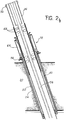
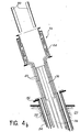
- FIGS. 4a and 5 show an alternative embodiment of the bushing assembly shown in FIGS. 2a and 3, in which instead of being arranged in the annular space defined between the ramp 36 and the ferrule 52, the heat pipes 60 are arranged inside the guide ramp 36 and on either side of the handling pot 34.
- This solution is thermally more efficient than the previous one, since the heat pipes are arranged in the immediate vicinity of the handling pot , and it eliminates the lights in the guide ramp, which allows a reduction in the thickness of the wall thereof and leads to a certain reduction in the radial size of the assembly at the crossing of the slab 20.
- the variant embodiment shown in FIGS. 4a and 5 however has the drawback that, the annular grille 64 remaining unchanged compared to the variant shown in FIG. 2a, the heat pipes 60 must cross the ramp 36 in the vicinity of the upper end of the ferrule 52. It follows that in order to dismantle the heat evacuation device 73 and the guide ramp 36, it is necessary to provide in the upper part of the latter at least one removable element disposed in the extension of each of the two groups of heat pipes 60.
- the upper part of the ramp 36 comprises two removable cylindrical sectors 80 each arranged in the extension of one of the groups of heat pipes 60 and of which disassembly first authorizes disassembly of the heat removal device 73 comprising the heat pipes 60 and the annular grille 64 and then disassembly of the ramp 36.
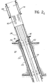
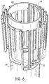
- the disassembly of the ramp 36 can only be carried out after removal of the heat removal device 73, this removal being itself conditioned by the disassembly of the panels 80 (first mode according to FIG. 4b) or of the crown 82 (second mode according to FIG. 6).
- the invention is not limited to the embodiments which have just been described by way of example, but covers all the variants thereof.
- such an assembly can be used each time that a handling pot containing an irradiated assembly must cross a containment slab whatever the path followed by this handling pot and even if this path is significantly different of that shown by way of example in FIG. 1.
- the handling pot containing the irradiated assemblies is guided directly inside the ramp crossing the slab or that it is placed at the inside of a carriage ensuring movement along the ramp.
Landscapes
- Physics & Mathematics (AREA)
- Engineering & Computer Science (AREA)
- Plasma & Fusion (AREA)
- General Engineering & Computer Science (AREA)
- High Energy & Nuclear Physics (AREA)
- Monitoring And Testing Of Nuclear Reactors (AREA)
- Heat-Exchange Devices With Radiators And Conduit Assemblies (AREA)
Applications Claiming Priority (2)
| Application Number | Priority Date | Filing Date | Title |
|---|---|---|---|
| FR7921762A FR2464539A1 (fr) | 1979-08-30 | 1979-08-30 | Ensemble de traversee de dalle de confinement pour transfert de combustible nucleaire irradie |
| FR7921762 | 1979-08-30 |
Publications (2)
| Publication Number | Publication Date |
|---|---|
| EP0024990A1 EP0024990A1 (fr) | 1981-03-11 |
| EP0024990B1 true EP0024990B1 (fr) | 1983-05-25 |
Family
ID=9229211
Family Applications (1)
| Application Number | Title | Priority Date | Filing Date |
|---|---|---|---|
| EP80401217A Expired EP0024990B1 (fr) | 1979-08-30 | 1980-08-26 | Ensemble de traversée de dalle de confinement pour transfert de combustible nucléaire irradié |
Country Status (5)
| Country | Link |
|---|---|
| US (1) | US4364899A (OSRAM) |
| EP (1) | EP0024990B1 (OSRAM) |
| DE (1) | DE3063508D1 (OSRAM) |
| ES (1) | ES8301053A1 (OSRAM) |
| FR (1) | FR2464539A1 (OSRAM) |
Families Citing this family (4)
| Publication number | Priority date | Publication date | Assignee | Title |
|---|---|---|---|---|
| FR2486297A1 (fr) * | 1980-07-01 | 1982-01-08 | Novatome | Dispositif de chargement et de dechargement d'assemblages combustibles pour reacteur nucleaire a neutrons rapides |
| FR2599542B1 (fr) * | 1986-05-29 | 1988-08-05 | Commissariat Energie Atomique | Installation de manutention des assemblages constituant le coeur d'un reacteur nucleaire a neutrons rapides |
| GB2372639A (en) | 2001-01-23 | 2002-08-28 | Swintex | An arrangement to wick/evapourate water away from the underside of a structure |
| US8270555B2 (en) * | 2008-05-01 | 2012-09-18 | Ge-Hitachi Nuclear Energy Americas Llc | Systems and methods for storage and processing of radioisotopes |
Family Cites Families (6)
| Publication number | Priority date | Publication date | Assignee | Title |
|---|---|---|---|---|
| NL247851A (OSRAM) * | 1959-01-29 | |||
| GB916820A (en) * | 1959-02-27 | 1963-01-30 | Gen Electric Co Ltd | Improvements in or relating to fuel feeding arrangements for nuclear reactors |
| FR2188251B1 (OSRAM) * | 1972-06-08 | 1976-01-16 | Commissariat A En Atomique Fr | |
| FR2267614A1 (en) * | 1974-04-11 | 1975-11-07 | Commissariat Energie Atomique | Articulated handling machines - which protect fast reactor containment vessel have links and release system to separate top and bottom portions of machine |
| FR2368121A1 (fr) * | 1976-10-15 | 1978-05-12 | Commissariat Energie Atomique | Dispositif de manutention a bras double pour reacteur nucleaire |
| FR2368122A1 (fr) * | 1976-10-15 | 1978-05-12 | Commissariat Energie Atomique | Dispositif de chargement et dechargement en combustible pour reacteur nucleaire |
-
1979
- 1979-08-30 FR FR7921762A patent/FR2464539A1/fr active Granted
-
1980
- 1980-08-15 US US06/178,290 patent/US4364899A/en not_active Expired - Lifetime
- 1980-08-26 EP EP80401217A patent/EP0024990B1/fr not_active Expired
- 1980-08-26 DE DE8080401217T patent/DE3063508D1/de not_active Expired
- 1980-08-29 ES ES494628A patent/ES8301053A1/es not_active Expired
Also Published As
| Publication number | Publication date |
|---|---|
| DE3063508D1 (en) | 1983-07-07 |
| FR2464539B1 (OSRAM) | 1983-09-30 |
| FR2464539A1 (fr) | 1981-03-06 |
| US4364899A (en) | 1982-12-21 |
| EP0024990A1 (fr) | 1981-03-11 |
| ES494628A0 (es) | 1982-11-01 |
| ES8301053A1 (es) | 1982-11-01 |
Similar Documents
| Publication | Publication Date | Title |
|---|---|---|
| FR2697104A1 (fr) | Réacteur rapide équipé d'un système de commande pour réflecteur. | |
| BE897468A (fr) | Procede de remplacement des broches de guidage d'un tube-guide et dispositif correspondant | |
| EP0004241B1 (fr) | Dispositif de jonction entre un conteneur et une enceinte de déchargement | |
| EP0024990B1 (fr) | Ensemble de traversée de dalle de confinement pour transfert de combustible nucléaire irradié | |
| FR2502829A1 (fr) | Installation de stockage de combustible nucleaire | |
| EP0032070B1 (fr) | Appareil pour traiter des composés dans un liquide | |
| FR2495815A1 (fr) | Reacteur nucleaire refroidi par un metal liquide contenu dans une cuve obturee par des fermetures superieures | |
| EP0173602B1 (fr) | Echangeur de chaleur de secours pour le refroidissement du fluide primaire d'un réacteur nucléaire et procédé de montage de cet échangeur de chaleur | |
| EP0083545B1 (fr) | Dispositif d'évacuation de secours de la chaleur dissipée par un réacteur nucléaire à neutrons rapides à l'arrêt | |
| EP0163564A1 (fr) | Reacteur nucléaire à neutrons rapides à générateur de vapeur intégré dans la cuve | |
| FR2743445A1 (fr) | Procede et dispositif de demantelement et d'evacuation d'equipements internes inferieurs d'un reacteur nucleaire refroidi par de l'eau sous pression | |
| EP0030884B1 (fr) | Appareil pour traiter des composés dans un liquide | |
| EP0258131B1 (fr) | Dispositif de refroidissement de secours d'un réacteur nulcléaire à neutrons rapides | |
| FR2582438A1 (fr) | Hotte de manutention et de transport d'assemblages de combustible nucleaire et installation comportant une hotte de ce type | |
| FR2555794A1 (fr) | Reacteur nucleaire a neutrons rapides equipe de moyens de refroidissement de secours | |
| EP0047698B1 (fr) | Réacteur nucléaire à circulation du fluide primaire de refroidissement par convection mixte | |
| WO1998001864A1 (fr) | Reacteur nucleaire comportant une cuve dans laquelle est dispose le coeur du reacteur et procede de refroidissement du coeur du reacteur a l'arret | |
| EP0267083A1 (fr) | Installation de manutention du combustible dans un réacteur nucléaire à neutrons rapides | |
| FR2735552A1 (fr) | Systeme d'etancheite pour l'accostage d'un conteneur sous un four de fusion | |
| FR2710182A1 (fr) | Procédé de démantèlement d'un générateur de vapeur usagé d'un réacteur nucléaire à eau sous pression. | |
| BE1011152A3 (fr) | Dispositif pour le groupement d'assemblages. | |
| EP0150148B1 (fr) | Réacteur nucléaire à neutrons rapides muni d'une cellule centrale de manutention et d'une dalle caissonnée | |
| EP0144256A1 (fr) | Dispositif de protection thermique d'un composant d'un réacteur nucléaire à neutrons rapides | |
| FR2625023A2 (fr) | Dispositif de jonction entre un conteneur de transport et une paroi horizontale d'une enceinte de dechargement | |
| EP0382643A1 (fr) | Dispositif de protection thermique de la virole supérieure de supportage d'une cuve suspendue, notamment dans un réacteur nucléaire à neutrons rapides |
Legal Events
| Date | Code | Title | Description |
|---|---|---|---|
| PUAI | Public reference made under article 153(3) epc to a published international application that has entered the european phase |
Free format text: ORIGINAL CODE: 0009012 |
|
| AK | Designated contracting states |
Designated state(s): BE DE GB IT NL |
|
| 17P | Request for examination filed |
Effective date: 19810813 |
|
| ITF | It: translation for a ep patent filed | ||
| GRAA | (expected) grant |
Free format text: ORIGINAL CODE: 0009210 |
|
| AK | Designated contracting states |
Designated state(s): BE DE GB IT NL |
|
| REF | Corresponds to: |
Ref document number: 3063508 Country of ref document: DE Date of ref document: 19830707 |
|
| PLBE | No opposition filed within time limit |
Free format text: ORIGINAL CODE: 0009261 |
|
| STAA | Information on the status of an ep patent application or granted ep patent |
Free format text: STATUS: NO OPPOSITION FILED WITHIN TIME LIMIT |
|
| 26N | No opposition filed | ||
| PGFP | Annual fee paid to national office [announced via postgrant information from national office to epo] |
Ref country code: BE Payment date: 19840930 Year of fee payment: 5 |
|
| PGFP | Annual fee paid to national office [announced via postgrant information from national office to epo] |
Ref country code: NL Payment date: 19860831 Year of fee payment: 7 |
|
| BERE | Be: lapsed |
Owner name: COMMISSARIAT A L'ENERGIE ATOMIQUE ETS DE CARACTER Effective date: 19870831 |
|
| PG25 | Lapsed in a contracting state [announced via postgrant information from national office to epo] |
Ref country code: NL Effective date: 19880301 |
|
| NLV4 | Nl: lapsed or anulled due to non-payment of the annual fee | ||
| PG25 | Lapsed in a contracting state [announced via postgrant information from national office to epo] |
Ref country code: BE Effective date: 19890831 |
|
| PGFP | Annual fee paid to national office [announced via postgrant information from national office to epo] |
Ref country code: DE Payment date: 19900724 Year of fee payment: 11 |
|
| PGFP | Annual fee paid to national office [announced via postgrant information from national office to epo] |
Ref country code: GB Payment date: 19900810 Year of fee payment: 11 |
|
| PG25 | Lapsed in a contracting state [announced via postgrant information from national office to epo] |
Ref country code: GB Effective date: 19910826 |
|
| GBPC | Gb: european patent ceased through non-payment of renewal fee | ||
| PG25 | Lapsed in a contracting state [announced via postgrant information from national office to epo] |
Ref country code: DE Effective date: 19920501 |