EP0024435B2 - Mig arc welding method - Google Patents
Mig arc welding method Download PDFInfo
- Publication number
- EP0024435B2 EP0024435B2 EP80900426A EP80900426A EP0024435B2 EP 0024435 B2 EP0024435 B2 EP 0024435B2 EP 80900426 A EP80900426 A EP 80900426A EP 80900426 A EP80900426 A EP 80900426A EP 0024435 B2 EP0024435 B2 EP 0024435B2
- Authority
- EP
- European Patent Office
- Prior art keywords
- welding
- arc
- wire
- rare earth
- polarity
- Prior art date
- Legal status (The legal status is an assumption and is not a legal conclusion. Google has not performed a legal analysis and makes no representation as to the accuracy of the status listed.)
- Expired
Links
Images

Classifications
-
- B—PERFORMING OPERATIONS; TRANSPORTING
- B23—MACHINE TOOLS; METAL-WORKING NOT OTHERWISE PROVIDED FOR
- B23K—SOLDERING OR UNSOLDERING; WELDING; CLADDING OR PLATING BY SOLDERING OR WELDING; CUTTING BY APPLYING HEAT LOCALLY, e.g. FLAME CUTTING; WORKING BY LASER BEAM
- B23K35/00—Rods, electrodes, materials, or media, for use in soldering, welding, or cutting
- B23K35/22—Rods, electrodes, materials, or media, for use in soldering, welding, or cutting characterised by the composition or nature of the material
- B23K35/24—Selection of soldering or welding materials proper
- B23K35/30—Selection of soldering or welding materials proper with the principal constituent melting at less than 1550°C
- B23K35/3053—Fe as the principal constituent
Definitions
- the present invnetion relates to MIG arc welding and is concerned with a novel welding technique which improves the arc stability and the transfer of the molten droplets of the welding wire whereby MIG arc welding can be carried out with direct current reverse polarity in a pure inert gas atmosphere, with direct current straight polarity, or with alternating current.
- MIG arc welding heretofore has used a mixed gas containing an appropriate amount (usually several %) of an active gas, such as oxygen or carbon dioxide gas, in an inert gas, such as argon gas in order to stabilize the arc, and a positive electrode system, that is direct current reverse polarity wherein a welding torch is connected to a positive electrode of a direct current power supply and the mother metal to be welded is connected to a negative electrode.
- an active gas such as oxygen or carbon dioxide gas
- an inert gas such as argon gas
- the mixing ratio of the active gas is not always constant depending upon the object of welding and the kind of welding wire and mother metal to be welded but, for example, it is well known that Sigma grade argon (Linde Co. Ltd. U.S.A.) containing 1-5% of oxygen in argon gas is effective to transfer the molten droplets at the wire tip in spray form.
- the mixing of the above described active gas with the inert gas is effective for stabilizing the welding arc and preventing the welding defects.
- the oxygen content in the welded metal is inevitably increased and, for example, when welding 9% Ni steel requiring high toughness of an ultra low temperature of about -196°C by using a wire having a similar composition to the mother metal (ferritic wire), this increase in oxygen content is incompatible with the toughness requirement.
- the presence of the active gas is not acceptable when welding where toughness is particularly important.
- US ⁇ A ⁇ 3 539 764 there is described an MIG arc welding technique wherein two electric power sources are used to control the arc voltage.
- One of these sources is a conventional electric power source arranged to apply a low direct voltage between the welding wire and the metal to be welded.
- the other is a pulse generator adapted to produce pulses of direct welding current at a predetermined frequency across the gap between the welding wire and the metal to be welded.
- the power sources are arranged so that a high voltage pulse is applied between the welding wire and the metal to be welded so that a molten metal drop is formed at the welding wire tip and then the wire and the metal to be welded are short-circuited at low voltage to transfer the molten metal drop.
- the arc is surrounded by a gaseous atmosphere which may include an inert gas.
- the present invention aims to provide a MIG arc welding method using a pure inert gas atmosphere in which the welding arc is stabilized and the molten droplets of the wire are smoothly transferred to the molten pool on the mother meal, with direct current reverse polarity, direct current straight polarity, and alternating current.
- the inventors have carried out a variety of experiments in order to prevent the irregular movement of the cathode spots with direct current reverse polarity and found that it is necessary to transfer the molten droplets at the wire tip by means of instantaneous short-circuits between the wire tip and the surface of the molten pool.
- rare earth element there is meant an element of the lanthanoid series having an atomic number of from 57 to 71.
- the wire tip is sharpened by the arc when using direct current reverse polarity to form a reverse conical shape having a sharp vertex angle and the sharpened wire tip is instantaneously short-circuited with the molten pool surface stably, repeatedly and continuously.
- the amount of rare earth elements present is less than 0.02% in weight, the above described sharpening and the stable metal transfer based on the instantaneous short-circuit do not occur.
- said amount exceeds 0.30% in weight, non-metallic inclusions in the welded metal are increased resulting in deterioration of the toughness.
- the rare earth should be present in the range of from 0.02 to 0.30% by weight.
- MIG arc welding can be stably carried out with direct current reverse polarity, straight polarity or alternating current in a pure inert gas atmosphere.
- active gas such as oxygen, carbon dioxide gas and the like
- inert gas for the stabilisation of the arc
- the zone defined by solid lines a in Fig. 1 represents the stable operation range when using reverse polarity.
- the wire used was one containing 0.10% of rare earth elements and having a diameter of 1.2 mm.
- the range defined by the upper and lower solid lines, wherein the molten droplets are stably transferred through instantaneous short-circuits, is extended as shown in Fig. 1 by the inclusion of rare earth elements in the wire.
- the situation is very different in the case of pure argon shielded conventional MIG arc welding using direct current reverse polarity wherein the wire thrusts suddenly into the molten pool as the arc voltage is lowered from the value at which an irregular spray arc is formed.
- the addition of rare earth elements shows a noticeable contribution to the above described arc stabilization when present in an amount of more than 0.02% in weight, but when said amount exceeds 0.30% in weight, non-metallic inclusions in the welded metal are increased and the toughness is deteriorated.
- the amount of rare earth addition should be from 0.02 to 0.30% in weight.
- rare earth element is preferably made in the form of Mischmetal which consists of about 50% Ce and 25% La. In this case it is convenient to define the total rare earth element content of the welding wire by determining the cerium content and multiplying this value by a factor of two.
- the welding phenomena are understood to be a combination of the straight polarity phenomena and the reverse polarity phenomena but, as already mentioned, the arc is suppressed at the alternating points between the two polarities, so that a very high voltage is necessary for reigniting the arc.
- the use of welding wire including from 0.02 to 0.30% by weight of rare earth elements can considerably reduce the above described reignition voltage and the molten droplets at the wire tip are transferred to the molten pool by the instantaneous short-circuits, whereby the stabilization of alternating current MIG arc welding can be advantageously attained.
- the preferred range of the welding voltage and current is the zone between the upper solid line a and the lower broken line P.
- usually used wires means usual steel wires having the basic compositions of C ⁇ 0.20% by weight, Si ⁇ 1.00% by weight, Mn ⁇ 2.50%, by weight, and P and S ⁇ 0.030% by weight or alloy steel wires containing at least one of Ni--20% by weight, Cr ⁇ 30% by weight and Mo ⁇ 10% by weight in addition to the above described components.
- Tables 2a and 2b show examples of welding carried out by using direct current reverse polarity in a pure argon shield.
- the molten droplets were stably transferred by the instantaneous short-circuits and very good welds were obtained.
- the measured welding conditions were roughly equal to the set values.
- Tables 3a and 3b show welding examples when direct current straight polarity was used in a pure argon shield gas.
- Tables 4a and 4b show examples when the welding was carried out using alternating current in a pure argon shield.
- the features of the alternating current arc are that, when the wire (No. 1) containing no rare earth elements was used, the reignition of the arc was not stably conducted, so that continuation of welding was quite impossible.
- the wires (Nos. 2-5) containing 0.02 to 0.30% by weight of rare earth elements were used, the arcs in both the negative and the positive half wave zones were stabilized and also the reignition characteristics at the alternating points were stabilized. Welds of very high quality were obtained. When the content of rare earth elements was increased to 0.36% in weight, the cleanliness of the welded metal was deteriorated and such welding was not practical.
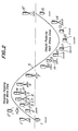
- Figure 2 is a schematic illustration of the metal transfer phenomena and the arc behaviour during one cycle of alternating current MIG arc welding in pure argon gas.
- s represents the welding current wave shape
- w is a welding wire containing an appropriate amount of rare earth elements
- p is a molten pool surface formed on a mother metal to be welded
- zones c and f indicated by broken lines are primary and secondary arcs respectively
- d is a molten droplet formed at the welding wire tip by the arc heat
- t is a wire tip causing instantaneous short-circuit.
- the left half in Figure 2 shows the reverse polarity half wave and at the beginning of the said zone 1-4, the tip of wire w is melted by the arc heat and a molten droplet d transfers to the molten pool hanging from the partly sharpened wire tip. After the metal transfer the tip of the wire w is fully sharpened at the time point 5.
- the sharpened tip touches the surface of the molten pool and maintains stable instantaneous short-circuits. Almost all the molten metal is transferred to the mother plate through these instantaneous short-circuits having a frequency of about 250 Hz.
- the arcs c and f disappear and at this instant the sharpened tip of wire w remains.
- the arc f is reignited at the root of the sharpened tip m which is subsequently fused down. Thereafter, there is no noticeable variation in welding phenomena along the time points 10-13 and the molten droplet d accumulated at the tip of the wire w during the last half of the straight polarity is either transferred to the mother metal at the time point 14 or is retained without transferring.
- the instantaneous short-circuit transfer as shown at time points 5-7 in Figure 2 is continued, while in the case of direct current straight polarity, the instantaneous short-circuit transfer as shown at time point 14 in Figure 2 is stably continued at a frequency of about 60 Hz.
- the effect of the present invention has been explained with respect to test specimens of mild steel, but the present invention can also be advantageously applied to the welding of all alloy steels, such as 9% Ni as mentioned hereinbefore and in this case substantially the same effect can be obtained.
- alternating current MIG arc welding By applying the method of the invention to alternating current MIG arc welding, welding can be satisfactorily carried out using an alternating current supply for manual metal arc welding which is a cheap welding power supply. It is not necessary to install an expensive direct current welding power supply. Also, in alternating current MIG arc welding, the current flows pulsatory, so that the alternating current MIG arc is hardly subjected to the adverse influence of external magnetic fields (for example, residual magnetism of the mother metal) as is the case with direct current arcs and the problem of magnetic arc blow can be solved. Further the reignition voltage is low, so that the weldig arc can be stabilized even with a low no-load voltage of the power supply. Accordingly, no specific apparatus is needed to stabilise the reignition characteristics and the danger of electric shock can be minimized.
- external magnetic fields for example, residual magnetism of the mother metal
Landscapes
- Engineering & Computer Science (AREA)
- Mechanical Engineering (AREA)
- Arc Welding In General (AREA)
- Arc Welding Control (AREA)
Abstract
Description
- The present invnetion relates to MIG arc welding and is concerned with a novel welding technique which improves the arc stability and the transfer of the molten droplets of the welding wire whereby MIG arc welding can be carried out with direct current reverse polarity in a pure inert gas atmosphere, with direct current straight polarity, or with alternating current.
- In general, MIG arc welding heretofore has used a mixed gas containing an appropriate amount (usually several %) of an active gas, such as oxygen or carbon dioxide gas, in an inert gas, such as argon gas in order to stabilize the arc, and a positive electrode system, that is direct current reverse polarity wherein a welding torch is connected to a positive electrode of a direct current power supply and the mother metal to be welded is connected to a negative electrode.
- The reasons why the above described active gas component should be mixed in the shield gas are as follows. Firstly, if a pure inert gas atmosphere i.e. one with no active gas component is used, arc roots (cathode spots) do not take fixed positions on the mother metal to be welded and move around on the mother metal surface sputtering from mill scales present on the surface so that the arc trembles and the welding wire is irregularly fused and therefore a satisfactory welding result can be obtained. Secondly, in the welded metal obtained with a pure inert gas atmosphere, a finger-shape weld penetration is formed at the bottom of a weld puddle and at this portion, insufficient fusion, slag inclusion, blow holes and other welding defects are caused and the addition of an active gas component prevents these defects.
- In view of the need for the welded joints to be safe, the above described defects cannot be accepted. Hence, in order to obtain sound welded joints having no such defects. It has been essential to add an appropriate amount of active gas to the inert gas to stabilize the arc and prevent the defects.
- The mixing ratio of the active gas is not always constant depending upon the object of welding and the kind of welding wire and mother metal to be welded but, for example, it is well known that Sigma grade argon (Linde Co. Ltd. U.S.A.) containing 1-5% of oxygen in argon gas is effective to transfer the molten droplets at the wire tip in spray form.
- Thus, the mixing of the above described active gas with the inert gas is effective for stabilizing the welding arc and preventing the welding defects. However, the oxygen content in the welded metal is inevitably increased and, for example, when welding 9% Ni steel requiring high toughness of an ultra low temperature of about -196°C by using a wire having a similar composition to the mother metal (ferritic wire), this increase in oxygen content is incompatible with the toughness requirement. Thus the presence of the active gas is not acceptable when welding where toughness is particularly important.
- As mentioned above, prior MIG arc welding has practically always used direct current reverse polarity, becuase this enables the molten droplets of the wire to be smoothly transferred to the mother metal to be welded and a good welded bead to be formed. When direct current straight polarity is used wherein the welding torch is connected to a negative electrode of the direct current power supply and the mother metal to be welded is connected to a positive electrode, a strong arc force acts against the molten droplets of the wire to push up the molten droplets. Thus the molten droplets are transferred to the mother metal in such a form that they are torn off and result in large splatters whereby the formation of practically usable beads is substantially impossible.
- In alternating current MIG arc welding wherein the polarity is periodically alternated, the molten droplets are unstably transferred in the half wave wherein the polarity becomes straight polarity and hence the formation of a good bead is hampered. Further when the current value becomes zero at the alternating points, where the arc is suppressed, a high voltage of about 300 V is necessary to reignite the arc and a large capacity welding power supply is needed. In such a case, if the welding operator receives an electric shock the danger is high. Thus, the use of such a high voltage power supply is not preferred in practice.
- For the above described reasons, MIG arc welding using direct current straight polarity or alternating current has never been practised commercially.
- In US―A―3 539 764 there is described an MIG arc welding technique wherein two electric power sources are used to control the arc voltage. One of these sources is a conventional electric power source arranged to apply a low direct voltage between the welding wire and the metal to be welded. The other is a pulse generator adapted to produce pulses of direct welding current at a predetermined frequency across the gap between the welding wire and the metal to be welded. The power sources are arranged so that a high voltage pulse is applied between the welding wire and the metal to be welded so that a molten metal drop is formed at the welding wire tip and then the wire and the metal to be welded are short-circuited at low voltage to transfer the molten metal drop. The arc is surrounded by a gaseous atmosphere which may include an inert gas.
- In US―A―1 352 534 there is described welding wires containing zirconium or a rare earth metal for use in either electric or gaseous welding operations. The purpose of this addition is to avoid the formation of oxides and nitrides in the weld metal.
- The present invention aims to provide a MIG arc welding method using a pure inert gas atmosphere in which the welding arc is stabilized and the molten droplets of the wire are smoothly transferred to the molten pool on the mother meal, with direct current reverse polarity, direct current straight polarity, and alternating current.
- The inventors have carried out a variety of experiments in order to prevent the irregular movement of the cathode spots with direct current reverse polarity and found that it is necessary to transfer the molten droplets at the wire tip by means of instantaneous short-circuits between the wire tip and the surface of the molten pool.
- However, with welding wires having normal chemical compositions, it is generally difficult to stably maintain the above described instantaneous short-circuits in pure argon gas atmosphere; either the wire thrusts into the molten pool to form spatters or an unstable spray arc accompanied by an irregular motion of cathode spots is formed.
- The inventors have found after a large number of trials and errors that it is effective to include not less than 0.02 weight % of rare earth element in the welding wire for causing instantaneous repetition of the stable short-circuit between the molten droplets at the wire tip and the molten pool surface. By the term "rare earth element" there is meant an element of the lanthanoid series having an atomic number of from 57 to 71.
- When such a welding wire is used together with pure argon gas, which is a typical example of pure inert shielding gas, the wire tip is sharpened by the arc when using direct current reverse polarity to form a reverse conical shape having a sharp vertex angle and the sharpened wire tip is instantaneously short-circuited with the molten pool surface stably, repeatedly and continuously. When the amount of rare earth elements present is less than 0.02% in weight, the above described sharpening and the stable metal transfer based on the instantaneous short-circuit do not occur. When said amount exceeds 0.30% in weight, non-metallic inclusions in the welded metal are increased resulting in deterioration of the toughness. Thus the rare earth should be present in the range of from 0.02 to 0.30% by weight.
- Thus, according to the present invention, which in its broadest scope is defined by the method of claim 1, MIG arc welding can be stably carried out with direct current reverse polarity, straight polarity or alternating current in a pure inert gas atmosphere. In any case, it is not necessary to add active gas, such as oxygen, carbon dioxide gas and the like to an inert gas for the stabilisation of the arc, whereby the amount of oxygen in the welded metal is decreased and the toughness is conspicuously improved and welding defects are not caused.
-
- Figure 1 is a graph of arc voltage against welding current; and
- Figure 2 is a schematic illustration of metal transfer and the arc configuration when an alternating current is applied in a welding method according to the present invention.
- By using a welding wire containing an appropriate amount of rare earth elements, pure argon shielding gas and an ordinary welding power supply, tests were carried out to determine stable operation ranges with respect to the relationship between the welding current and the arc voltage for maintaining instantaneous short-circuit transfer and satisfactory welded bead. The zone defined by solid lines a in Fig. 1 represents the stable operation range when using reverse polarity. The wire used was one containing 0.10% of rare earth elements and having a diameter of 1.2 mm. Although the above described conditions vary to some extent depending upon the wire diameter and the current value, in the zone below the lower solid line in Figure 1, the wire thrusts into the molten pool, while in the zone above the upper solid line, the arc becomes unstable. The range defined by the upper and lower solid lines, wherein the molten droplets are stably transferred through instantaneous short-circuits, is extended as shown in Fig. 1 by the inclusion of rare earth elements in the wire. The situation is very different in the case of pure argon shielded conventional MIG arc welding using direct current reverse polarity wherein the wire thrusts suddenly into the molten pool as the arc voltage is lowered from the value at which an irregular spray arc is formed.
- The addition of rare earth elements shows a noticeable contribution to the above described arc stabilization when present in an amount of more than 0.02% in weight, but when said amount exceeds 0.30% in weight, non-metallic inclusions in the welded metal are increased and the toughness is deteriorated. Thus the amount of rare earth addition should be from 0.02 to 0.30% in weight.
- The addition of rare earth element is preferably made in the form of Mischmetal which consists of about 50% Ce and 25% La. In this case it is convenient to define the total rare earth element content of the welding wire by determining the cerium content and multiplying this value by a factor of two.
- When a welding wire including an appropriate amount of rare earth element as mentioned above is applied to MIG arc welding with direct current straight polarity, it has been found that the great problem which ordinarily arises when using a welding wire having a prior normal composition (that is, the problem of the molten droplets at the wire tip melted by the arc heat being pushed up by a strong arc force to form a large lump and being not smoothly transferred to the mother metal) is advantageously overcome and the molten droplets are smoothly transferred by the instantaneous short-circuits. In addition, it has been found that the welding conditions causing such a specific transfer of the molten droplets are within the range defined by the upper and lower broken lines (3 in Fig. 1. The critical value of the amount of rare earth element added, which suppresses the growth of the molten droplets at the wire tip and causes the smooth transfer based on instantaneous short-circuits, is the same as that with direct current reverse polarity.
- In alternating current MIG arc welding, in which the straight polarity and the reverse polarity are periodically alternated, the welding phenomena are understood to be a combination of the straight polarity phenomena and the reverse polarity phenomena but, as already mentioned, the arc is suppressed at the alternating points between the two polarities, so that a very high voltage is necessary for reigniting the arc. However, it has been found that the use of welding wire including from 0.02 to 0.30% by weight of rare earth elements can considerably reduce the above described reignition voltage and the molten droplets at the wire tip are transferred to the molten pool by the instantaneous short-circuits, whereby the stabilization of alternating current MIG arc welding can be advantageously attained. In this case, the preferred range of the welding voltage and curent is the zone between the upper solid line a and the lower broken line P.
- When the content of rare earth element is less than 0.02% by weight, the arc and the metal transfer are not stabilized in direct current welding, and it is impossible to reduce reignition voltage in alternating current welding. On the other hand, when the content exceeds 0.30% by weight, non-metallic inclusions in the welded metal are increased and the toughness deteriorates. When welding is carried out conforming to the various conditions of the present invention, the resulting weld quality has nothing to do with the basic chemistry of the welding wires used, and the effect of the present invention can be developed with any kind of usually used wires. The term "usually used wires" used herein means usual steel wires having the basic compositions of C≤0.20% by weight, Si≤1.00% by weight, Mn≤2.50%, by weight, and P and S≤0.030% by weight or alloy steel wires containing at least one of Ni--20% by weight, Cr≤30% by weight and Mo≤10% by weight in addition to the above described components.
- Explanation will be made hereinafter with respect to examples wherein the welding was carried out according to the present invention using six kinds of wires containing 0-0.36% by weight of rare earth elements. The steel plates used in the test were mild steel plates having a thickness of 20 mm, and mill scales on the plate surfaces were completely removed prior to welding. The welding rate and the flow rate of shield gas were held constant at 60 cm/min and 40 I/min, respectively.

- Tables 2a and 2b show examples of welding carried out by using direct current reverse polarity in a pure argon shield.

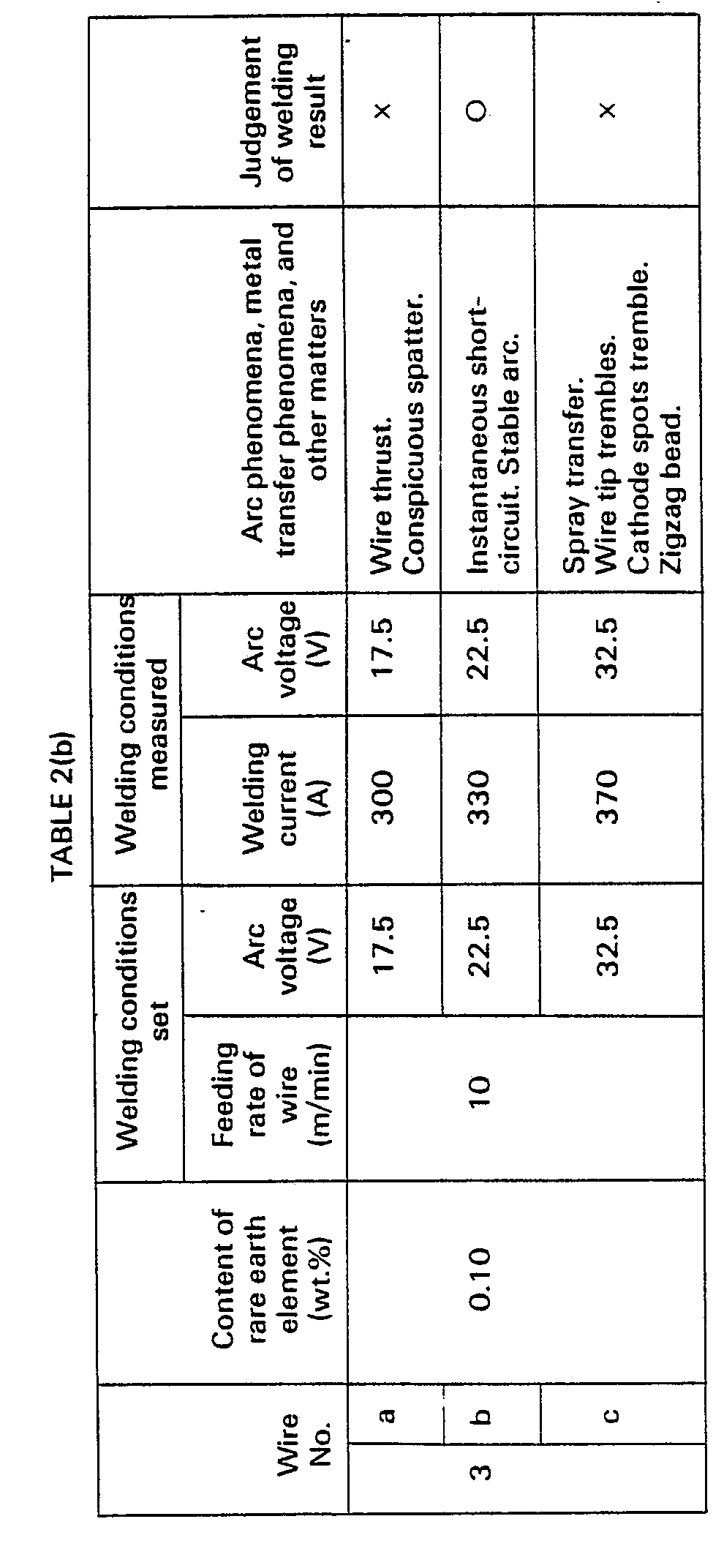
- With the wire (No. 1) containing no rare earth element, the wire tip thrusted into the molten pool and conspicuous spatters occurred. From the observation of the arc voltage wave form, many interruptions of the arc because of the wire thrusting (that is the occurrence of no load voltage) were found and as a result, a higher arc voltage than the set value was measured as seen in Table 2. In order to avoid the wire thrusting phenomenon, welding was attempted by gradually increasing the set arc voltage. At arc voltage values higher than a certain critical voltage, the wire thrusting phenomenon was solved but the wire tip unstably trembled in spray form and it was impossible to find a stable zone for instantaneous short-circuits.
- When the welding was carried out by using the wires (Nos. 2-5) containing 0.02-0.30% by weight of rare earth elements, the molten droplets were stably transferred by the instantaneous short-circuits and very good welds were obtained. The measured welding conditions were roughly equal to the set values.
- When the amount of rare earth elements added was increased to 0.36% by weight (wire No. 6), the welding arc itself was stable and the appearance of the welded bead was good, but the cleanliness of the welded metal was considerably deteriorated and, as a result, the toughness of the welded metal was degenerated. In the examples wherein the arc voltage was varied by using the wire (No. 3) containing 0.10% by weight of rare earth elements, at an arc voltage of 17.5 V, practically usable beads were not obtained because the wire thrusted into the molten pool and therefore spatters occurred. However such an unstable phenomenon that the set conditions could not be represented (as was the case with wire No. 1 containing no rare earth element) was not found. When the arc voltage ws 22.5 V, the sharpened wire tip was short-circuited with the molten pool surface in a very stable form to obtain a good welded bead. When the arc voltage was further raised to 32.5 V, the short-circuit at the wire tip was not stably maintained and the wire tip and the cathode spots unstably trembled, so that it was impossible to continue stable welding (the data shown in Table 1 complies with the phenomenon with direct current reverse polarity in Tables 2a and 2b).
- The following Tables 3a and 3b show welding examples when direct current straight polarity was used in a pure argon shield gas.


- When the wire (No. 1) containing no rare earth elements was used, it was difficult to transfer the molten droplets to the mother metal because of the strong arc force and hence the molten droplets grew to form a large lump at the wire tip and scattered irregularly. Further the arc itself was very unstable and it was difficult to represent the set conditions. When the wires (Nos. 2-5) containing rare earth elements within the range of 0.02-0.30% by weight were used, the arc force was weakened due to the stabilizing effect of the rare earth elements on cathode spots and the molten droplets at the wire tip were smoothly transferred accompanying the instantaneous short-circuit to obtain a very stabilized bead. However, when the amount of rare earth elements added was increased to 0.36% by weight, although the stability of the arc itself and the appearance of the bead were good, a large amount of non-metallic inclusions were included in the welded metal and the toughness of the welded metal was deteriorated.
- When the arc voltage was varied by using the wire (No. 3) containing 0.10% by weight of rare earth elements, in the case of 20.0 V, the wire thrusted into the molten pool and in the case of 35.0 V, small grains of molten droplets were transferred in a form such that they scattered in all directions so that practically usable beads were not obtained. However, at the intermediate voltage of 27.5 V, the instantaneous short-circuit was stably maintained and a very good welded bead was obtained (the data in Table 3 corresponds to the phenomenon of direct current straight polarity in Fig. 1).
- The following Tables 4a and 4b show examples when the welding was carried out using alternating current in a pure argon shield.


- From these examples, it can be understood that the addition of rare earth elements in the claimed quantities is effective for stabilizing alternating current MIG arcs.
- The features of the alternating current arc are that, when the wire (No. 1) containing no rare earth elements was used, the reignition of the arc was not stably conducted, so that continuation of welding was quite impossible. However, when the wires (Nos. 2-5) containing 0.02 to 0.30% by weight of rare earth elements were used, the arcs in both the negative and the positive half wave zones were stabilized and also the reignition characteristics at the alternating points were stabilized. Welds of very high quality were obtained. When the content of rare earth elements was increased to 0.36% in weight, the cleanliness of the welded metal was deteriorated and such welding was not practical.
- When welding was carried out by varying arc voltage using the wire (No. 3) containing 0.1 % by weight of rare earth elements, the arc voltage of 20.0 V was too low to prevent the wire thrusting into the molten pool and a good welded bead was not obtained. An arc voltage of 35.0 V was too high to maintain the instantaneous short-circuit and the wire tip trembled, so that a good welded bead was not obtained. In contrast to these, the intermediate voltage of 25.0 V stably maintained the instantaneous short-circuit and a good welded bead was obtained.
- Figure 2 is a schematic illustration of the metal transfer phenomena and the arc behaviour during one cycle of alternating current MIG arc welding in pure argon gas.
- In Figure 2, s represents the welding current wave shape, w is a welding wire containing an appropriate amount of rare earth elements, p is a molten pool surface formed on a mother metal to be welded, zones c and f indicated by broken lines are primary and secondary arcs respectively, d is a molten droplet formed at the welding wire tip by the arc heat, and t is a wire tip causing instantaneous short-circuit.
- The numbers in Figure 2 correspond to successive instants along the time axis of the welding current wave s and show the relationship of arc behaviour and metal transfer to current variation. Furthermore, 1', 2', and 15' show an embodiment of a state different to that of 1, 2 and 15, respectively.
- The left half in Figure 2 shows the reverse polarity half wave and at the beginning of the said zone 1-4, the tip of wire w is melted by the arc heat and a molten droplet d transfers to the molten pool hanging from the partly sharpened wire tip. After the metal transfer the tip of the wire w is fully sharpened at the time point 5. Thus in the last period 5 to 7 in the above described half wave zone, the sharpened tip touches the surface of the molten pool and maintains stable instantaneous short-circuits. Almost all the molten metal is transferred to the mother plate through these instantaneous short-circuits having a frequency of about 250 Hz.
- When the present invention is applied to alternating current MIG arc welding, the major part of the metal transfer occurs during the last half of the reverse polarity period. Little transfer to molten droplets occurs during the straight polarity period.
- At the time point 8 where the polarity is alternated from reverse polarity to straight polarity, the arcs c and f disappear and at this instant the sharpened tip of wire w remains. At the time point 9 immediately after having entered the straight polarity, the arc f is reignited at the root of the sharpened tip m which is subsequently fused down. Thereafter, there is no noticeable variation in welding phenomena along the time points 10-13 and the molten droplet d accumulated at the tip of the wire w during the last half of the straight polarity is either transferred to the mother metal at the
time point 14 or is retained without transferring. After thetime point 15 or 15' as the case may be (that is, during the next reverse polarity period) the already mentioned events occur (points 1, 2 etc.) or the molten drop (1') is transferred at time point 2' and then the aforementioned events occur (points 3, 4 etc.). - In the MIG arc welding using direct current reverse polarity, the instantaneous short-circuit transfer as shown at time points 5-7 in Figure 2 is continued, while in the case of direct current straight polarity, the instantaneous short-circuit transfer as shown at
time point 14 in Figure 2 is stably continued at a frequency of about 60 Hz. - In the above described examples, the effect of the present invention has been explained with respect to test specimens of mild steel, but the present invention can also be advantageously applied to the welding of all alloy steels, such as 9% Ni as mentioned hereinbefore and in this case substantially the same effect can be obtained.
- By applying the method of the invention to alternating current MIG arc welding, welding can be satisfactorily carried out using an alternating current supply for manual metal arc welding which is a cheap welding power supply. It is not necessary to install an expensive direct current welding power supply. Also, in alternating current MIG arc welding, the current flows pulsatory, so that the alternating current MIG arc is hardly subjected to the adverse influence of external magnetic fields (for example, residual magnetism of the mother metal) as is the case with direct current arcs and the problem of magnetic arc blow can be solved. Further the reignition voltage is low, so that the weldig arc can be stabilized even with a low no-load voltage of the power supply. Accordingly, no specific apparatus is needed to stabilise the reignition characteristics and the danger of electric shock can be minimized.
Claims (5)
Applications Claiming Priority (2)
| Application Number | Priority Date | Filing Date | Title |
|---|---|---|---|
| JP54020577A JPS6012151B2 (en) | 1979-02-23 | 1979-02-23 | MIG arc welding method for rope |
| JP20577/79 | 1979-02-23 |
Publications (4)
| Publication Number | Publication Date |
|---|---|
| EP0024435A1 EP0024435A1 (en) | 1981-03-11 |
| EP0024435A4 EP0024435A4 (en) | 1982-01-08 |
| EP0024435B1 EP0024435B1 (en) | 1984-06-20 |
| EP0024435B2 true EP0024435B2 (en) | 1989-02-08 |
Family
ID=12031052
Family Applications (1)
| Application Number | Title | Priority Date | Filing Date |
|---|---|---|---|
| EP80900426A Expired EP0024435B2 (en) | 1979-02-23 | 1980-09-10 | Mig arc welding method |
Country Status (5)
| Country | Link |
|---|---|
| US (1) | US4313045A (en) |
| EP (1) | EP0024435B2 (en) |
| JP (1) | JPS6012151B2 (en) |
| DE (1) | DE3068280D1 (en) |
| WO (1) | WO1980001770A1 (en) |
Families Citing this family (11)
| Publication number | Priority date | Publication date | Assignee | Title |
|---|---|---|---|---|
| JPS6057422B2 (en) * | 1981-05-07 | 1985-12-14 | 川崎製鉄株式会社 | MIG arc welding method |
| JPS57202983A (en) * | 1981-06-06 | 1982-12-13 | Nippon Steel Corp | Consumable electrode type arc welding method for steel |
| JPS6133790A (en) * | 1984-07-24 | 1986-02-17 | Kawasaki Steel Corp | Wire for mig arc welding of cr-mo steel |
| US4999478A (en) * | 1989-10-23 | 1991-03-12 | Alloy Rods Global, Inc. | Metal cored electrode |
| JP5057615B2 (en) * | 2001-06-19 | 2012-10-24 | Jfeスチール株式会社 | Manufacturing method of welded joint |
| US20040140303A1 (en) * | 2002-01-31 | 2004-07-22 | Tokihiko Kataoka | Steel wire for carbon dioxide shielded arc welding and welding process using the same |
| US6784402B2 (en) * | 2002-03-27 | 2004-08-31 | Jfe Steel Corporation | Steel wire for MAG welding and MAG welding method using the same |
| US9643284B2 (en) | 2005-06-10 | 2017-05-09 | National Institute For Materials Science | Welding wire and welding method |
| WO2006132373A1 (en) * | 2005-06-10 | 2006-12-14 | National Institute For Materials Science | Welding wire and method of welding |
| JP5303112B2 (en) * | 2007-01-19 | 2013-10-02 | 川崎重工業株式会社 | MIG welding method |
| JP5022428B2 (en) * | 2009-11-17 | 2012-09-12 | 株式会社神戸製鋼所 | MIG arc welding wire for hardfacing and MIG arc welding method for hardfacing |
Family Cites Families (7)
| Publication number | Priority date | Publication date | Assignee | Title |
|---|---|---|---|---|
| US1352534A (en) * | 1919-06-24 | 1920-09-14 | Air Reduction | Welding-rod |
| US2694763A (en) * | 1952-05-17 | 1954-11-16 | Air Reduction | Electric arc welding |
| US2694764A (en) * | 1952-05-17 | 1954-11-16 | Air Reduction | Electric arc welding |
| US3035154A (en) * | 1958-10-28 | 1962-05-15 | Linde Eismasch Ag | Protective gas mixture for arc welding with a fusible bare metal wire electrode |
| GB1106686A (en) * | 1964-12-15 | 1968-03-20 | British Oxygen Co Ltd | Gas shielded electric arc welding |
| BE685622A (en) * | 1966-08-17 | 1967-02-01 | ||
| DE2434875A1 (en) * | 1974-07-19 | 1976-02-05 | Bayer Ag | FERTILIZER FOR SUPPLYING PLANTS WITH MICRONAURANT |
-
1979
- 1979-02-23 JP JP54020577A patent/JPS6012151B2/en not_active Expired
-
1980
- 1980-02-21 WO PCT/JP1980/000024 patent/WO1980001770A1/en not_active Ceased
- 1980-02-21 DE DE8080900426T patent/DE3068280D1/en not_active Expired
- 1980-09-10 EP EP80900426A patent/EP0024435B2/en not_active Expired
- 1980-10-23 US US06/201,408 patent/US4313045A/en not_active Expired - Lifetime
Also Published As
| Publication number | Publication date |
|---|---|
| JPS55114469A (en) | 1980-09-03 |
| EP0024435A4 (en) | 1982-01-08 |
| JPS6012151B2 (en) | 1985-03-30 |
| EP0024435A1 (en) | 1981-03-11 |
| US4313045A (en) | 1982-01-26 |
| DE3068280D1 (en) | 1984-07-26 |
| WO1980001770A1 (en) | 1980-09-04 |
| EP0024435B1 (en) | 1984-06-20 |
Similar Documents
| Publication | Publication Date | Title |
|---|---|---|
| CA1189152A (en) | Welding system | |
| EP0024435B1 (en) | Mig arc welding method | |
| US20080142490A1 (en) | Gas-shielded arc welding method | |
| US20050205525A1 (en) | Metal-core gas metal arc welding of ferrous steels with noble gas shielding | |
| EP1676663A2 (en) | Shielding gases and methods for gas-shielded metal arc welding with polarity changing | |
| US3066215A (en) | Welding method and product | |
| US3143631A (en) | Electric arc welding | |
| AU773498B2 (en) | Process for the mig welding of aluminum and its alloys with a shielding gas of the Ar/He/O2 type | |
| US6069336A (en) | Plasma or TIG welding or cutting process with a non-oxidizing gas having a low H2 O and/or O2 impurity content | |
| US3143630A (en) | Electric arc welding | |
| JP2711130B2 (en) | Gas shielded arc welding wire | |
| Singaravelu et al. | Modified short arc gas metal arc welding process for root pass welding applications | |
| JPH01299768A (en) | Consumable electrode type rectangular wave ac arc welding method | |
| US2863981A (en) | Metal arc welding | |
| US2988627A (en) | Metal arc welding | |
| AU2240800A (en) | Process for the mig welding of aluminium and its alloys in pulsed mode or unmodulated-spray mode | |
| US3185812A (en) | Gas-shielded electric arc welding | |
| RU2225286C1 (en) | Charge of powder wire for surfacing mean- and high-hardness steel | |
| US3557340A (en) | Selenium bearing wire for steel welding | |
| JPH0999390A (en) | Solid wire for pulse mag welding | |
| US2950377A (en) | Metal arc welding | |
| Ratz et al. | The Weldability of Sulfide Shape Controlled Linepipe and HSLA Steels | |
| JPS59159275A (en) | Mig arc welding method | |
| KIM AND JW MORRIS | The Development of a Ferritic Consumable for Welding Grain-Refined Fe-12Ni-0.25 Ti to Retain Toughness at 4.2 K | |
| DE102007032574A1 (en) | Arc joining process with flat wire |
Legal Events
| Date | Code | Title | Description |
|---|---|---|---|
| PUAI | Public reference made under article 153(3) epc to a published international application that has entered the european phase |
Free format text: ORIGINAL CODE: 0009012 |
|
| 17P | Request for examination filed |
Effective date: 19801113 |
|
| AK | Designated contracting states |
Designated state(s): DE FR GB |
|
| DET | De: translation of patent claims | ||
| GRAA | (expected) grant |
Free format text: ORIGINAL CODE: 0009210 |
|
| AK | Designated contracting states |
Designated state(s): DE FR GB |
|
| REF | Corresponds to: |
Ref document number: 3068280 Country of ref document: DE Date of ref document: 19840726 |
|
| ET | Fr: translation filed | ||
| PLBI | Opposition filed |
Free format text: ORIGINAL CODE: 0009260 |
|
| 26 | Opposition filed |
Opponent name: SANDVIK AKTIEBOLAG Effective date: 19850311 |
|
| PUAH | Patent maintained in amended form |
Free format text: ORIGINAL CODE: 0009272 |
|
| STAA | Information on the status of an ep patent application or granted ep patent |
Free format text: STATUS: PATENT MAINTAINED AS AMENDED |
|
| 27A | Patent maintained in amended form |
Effective date: 19890208 |
|
| AK | Designated contracting states |
Kind code of ref document: B2 Designated state(s): DE FR GB |
|
| ET3 | Fr: translation filed ** decision concerning opposition | ||
| PGFP | Annual fee paid to national office [announced via postgrant information from national office to epo] |
Ref country code: FR Payment date: 19930209 Year of fee payment: 14 |
|
| PGFP | Annual fee paid to national office [announced via postgrant information from national office to epo] |
Ref country code: GB Payment date: 19930210 Year of fee payment: 14 |
|
| PGFP | Annual fee paid to national office [announced via postgrant information from national office to epo] |
Ref country code: DE Payment date: 19930308 Year of fee payment: 14 |
|
| PG25 | Lapsed in a contracting state [announced via postgrant information from national office to epo] |
Ref country code: GB Effective date: 19940221 |
|
| GBPC | Gb: european patent ceased through non-payment of renewal fee |
Effective date: 19940221 |
|
| PG25 | Lapsed in a contracting state [announced via postgrant information from national office to epo] |
Ref country code: FR Effective date: 19941031 |
|
| PG25 | Lapsed in a contracting state [announced via postgrant information from national office to epo] |
Ref country code: DE Effective date: 19941101 |
|
| REG | Reference to a national code |
Ref country code: FR Ref legal event code: ST |