EP0023806A2 - Ribbon supply and printing apparatus with a flexible ribbon leader, and method of forming such a flexible ribbon leader - Google Patents
Ribbon supply and printing apparatus with a flexible ribbon leader, and method of forming such a flexible ribbon leader Download PDFInfo
- Publication number
- EP0023806A2 EP0023806A2 EP80302544A EP80302544A EP0023806A2 EP 0023806 A2 EP0023806 A2 EP 0023806A2 EP 80302544 A EP80302544 A EP 80302544A EP 80302544 A EP80302544 A EP 80302544A EP 0023806 A2 EP0023806 A2 EP 0023806A2
- Authority
- EP
- European Patent Office
- Prior art keywords
- ribbon
- leader
- discontinuities
- flexible
- integral member
- Prior art date
- Legal status (The legal status is an assumption and is not a legal conclusion. Google has not performed a legal analysis and makes no representation as to the accuracy of the status listed.)
- Granted
Links
- 238000007639 printing Methods 0.000 title claims abstract description 14
- 238000000034 method Methods 0.000 title claims description 12
- 238000005452 bending Methods 0.000 claims abstract description 12
- 238000003860 storage Methods 0.000 claims description 7
- 238000005520 cutting process Methods 0.000 claims description 3
- 238000001125 extrusion Methods 0.000 claims description 2
- 238000004519 manufacturing process Methods 0.000 description 6
- 239000004033 plastic Substances 0.000 description 6
- 229920003023 plastic Polymers 0.000 description 6
- 230000008569 process Effects 0.000 description 4
- 230000009471 action Effects 0.000 description 3
- 239000000463 material Substances 0.000 description 3
- 238000012986 modification Methods 0.000 description 2
- 230000004048 modification Effects 0.000 description 2
- 238000000465 moulding Methods 0.000 description 2
- 239000004743 Polypropylene Substances 0.000 description 1
- 239000000853 adhesive Substances 0.000 description 1
- 230000001070 adhesive effect Effects 0.000 description 1
- 238000010276 construction Methods 0.000 description 1
- 238000013016 damping Methods 0.000 description 1
- 239000006260 foam Substances 0.000 description 1
- 230000006870 function Effects 0.000 description 1
- 230000001788 irregular Effects 0.000 description 1
- 239000002184 metal Substances 0.000 description 1
- 238000010137 moulding (plastic) Methods 0.000 description 1
- -1 polypropylene Polymers 0.000 description 1
- 229920001155 polypropylene Polymers 0.000 description 1
- QQONPFPTGQHPMA-UHFFFAOYSA-N propylene Natural products CC=C QQONPFPTGQHPMA-UHFFFAOYSA-N 0.000 description 1
- 125000004805 propylene group Chemical group [H]C([H])([H])C([H])([*:1])C([H])([H])[*:2] 0.000 description 1
- 230000009467 reduction Effects 0.000 description 1
Images


Classifications
-
- B—PERFORMING OPERATIONS; TRANSPORTING
- B41—PRINTING; LINING MACHINES; TYPEWRITERS; STAMPS
- B41J—TYPEWRITERS; SELECTIVE PRINTING MECHANISMS, i.e. MECHANISMS PRINTING OTHERWISE THAN FROM A FORME; CORRECTION OF TYPOGRAPHICAL ERRORS
- B41J35/00—Other apparatus or arrangements associated with, or incorporated in, ink-ribbon mechanisms
- B41J35/04—Ink-ribbon guides
- B41J35/06—Ink-ribbon guides stationary
Definitions
- This invention relates to the handling of a flexible ribbon or tape, and more specifically, to the storage and transport of such ribbon or tape.
- the invention also relates to the storage and transport of ribbon or tape of the type utilized in serial impact printers.
- a typewriter as well as other forms of serial impact printers typically includes provision for relative motion between the impact means and the print receiving means so that the characters may be printed along a line.
- the print receiving medium is moved with respect to the character elements which remain stationary. That is, the platen and paper move with respect to the frame of the machine while the character elements are substantially fixed.
- the print elements are moved with respect to the platen. This is particularly important in certain typewriters and printers associated with word processors which are required to operate at very high speeds and to print in an automatic memory mode.
- the leader means comprises an integral member having discontinuities therein for controlling bending thereof.
- portions of the integral member adjacent the discontinuities abut one another when the integral member assumes a rectilinear, i.e., straight line configuration, so as to prevent reverse bending.
- the discontinuities may also serve to define hinge points so as to define bending along a predetermined path.
- the discontinuities of the preferred embodiment may comprise slits in the walls of an extruded integral member which forms a channel where the sidewalls of the channel are L-shaped in cross-section so as to enclose at least a portion of the ribbon.
- the base of the channel comprises a flexible web of material bends so as to form hinge points adjacent the slits. By locating the slits at regular integrals, uniformity in bending may be achieved.
- the base of the channel may also include longitudinally extending ridges so as to minimize friction between the leader means and the ribbon.
- This typewriter comprises a keyboard 10 which controls the motion of a print wheel 12 which preferably comprises a plurality of spokes having character elements formed at their ends and adapted to be impacted by a hammer 14 in order to drive a selected character element against a platen 16 over which a sheet of paper or other print receiving medium 18 may be interposed, although other character print and paper support means are within the scope of the invention.
- a print ribbon 20 is interposed between the character element 12 and the paper 18 so as to leave an inked impression corresponding to the character elements selected.
- the ribbon is shown being disposed as i rather below the print point defined by the position of the hammer 14. This is so that the operator of the typewriter can see what he or she has typed.
- the ribbon 20 is raised by lifter means (not shown) when the hammer 14 is about to impact the character element 12 and juxtaposed with respect thereto.
- the ribbon is carried by locator means 180 which is provided with an uplifted portion 181 under which the hammer and character element may pass on their way to the paper 18.
- the locator means 180 is mounted by means of posts 44 on a moving carriage 22 desirably driven by a linear stepper motor 26.
- the ribbon is then passed through flexible leaders 34 and 36 which are connected in turn to a ribbon cartridge 28 which is mounted within a receptacle 30.
- the flexible leaders 34 and 36 permit the locating means 180 to move with the carriage 22 while the cartridge 28 remains fixed, the flexible leaders 34 and 36 providing the interconnection therebetween.
- an erase ribbon 42 which may be supplied from a reel 38 and taken up by a second reel 40 and used to either overprint a letter struck in error or may be used to remove it, depending on the type of ink supplied by the ribbon.
- the cartridge 28 is connected to the flexible leader 200 by means of mounting structure 231 and 230. These are desirably mounted on the main section of the cartridge 28 so that the lid of the cartridge 232 may be made a simple part. Ribbon 20 is fed through first flexible leader 200 to locator 180 and returns by means of second flexible leader 200 back to cartridge 28.
- Locator 180 comprises a central section spacing ends 188 and 187 apart. These ends are adapted to mate with corresponding pieces of leader 200.
- the ends 187 and 188 are provided with shaped notches 183 which engage posts 184 which are mounted on the carriage of the typewriter and are, as discussed above, lifted when typing is performed so as to interpose the ribbon 20 between a selected character element and paper 18.
- a raised central portion 181 of the locator 180 is provided so that the hammer 14 and character element 12 may pass therethrough on their way to impact the paper.
- the ends of the locator 180 are provided with fingers 182 which may be operated by the operator when changing ribbons in order to open notches 183 so as to disengage locator 180 from posts 184.
- the ribbon 20 is shown being unwound from a supply reel 60 by means of a capstan 70 which is desirably driven by a stepper motor mounted on the typewriter (not shown). Ribbon 20 then passes around two guide posts 98, over a roller 100, and exits the cartridge 28 by means of leader mounting structure 231 and leader 200, thence to pass to the print point. After being typed upon, the ribbon 20 is returned, again via leader 200 and leader mounting structure 230, over a post 102 and onto a take-up reel 64.
- Said supply and take-up reels 60 and 64, respectively, (which in a preferred embodiment are flangeless coils of ribbon) are mounted concentrically on a hub 62 and are both driven by means of the stepper motor, not shown, acting on capstan 70.
- the take-up is driven by means of an intermediary O-ring 80 and a star wheel 76 which is pep- vided with teeth 78 which engage the typed-upon ribbon as it is wound onto the take-up reel 64.
- Said O-ring may desirably be passed over an intermediate pulley 92 which may be arranged so as to exert an inward tension (i.e., a tension acting toward the hub 62) on the arm 86 on which the star wheel 76 is mounted so as to keep the star wheel 76 in engagement with take-up reel 64.
- an inward tension i.e., a tension acting toward the hub 62
- the star wheel 76 by an integral molding process, whereby a plastic wheel is formed around a stamped metal star; in this way, an effective and unitary construction may be formed simply and inexpensively.
- the capstan is shown as comprising a resilient band around its lower circumference which drives the inked ribbon. It is also, in some circumstances, desirable to form this tire integrally with the capstan by means of an integral molding process. In other cases, a resilient band of the proper size may be slipped over the capstan.
- FIG. 5 an overall schematic of the ribbon cartridge system of the invention is shown.
- the ribbon is both supplied from and taken up in cartridge 28 and passed through leader 200 on its way to and returning : from the print point which is symbolized by hammer 14.
- the ribbon 20 is exposed in the region of the print point by locator 180 which is shown in further detail in Figure 2.
- An arrow is provided showing that the hammer and locator 180 move back and forth with respect to the cartridge 28, as is permitted by the flexibility of leader 200.
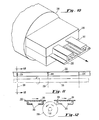
- the leader 200 essentially comprises a number of short sections which are substantially rigid but which are hinged one to the next. This is made readily possible by the design of the leader used, which is shown in further detail in Figure 6.
- the leader 200 comprises a flat web section 205, and uplifted L-shaped sections 203 within a ribbon (indicated schematically by a dot-dash line 202 rides).
- Slits 204 are provided in the uplifted L-shaped portions 203.
- the slits 204 allow the web 205 to become a hinge at each slit 204, thus permitting the leader 200 to comprise a number of short, comparatively rigid pieces but provide a flexible ribbon path since the leader 200 will not flex other than where slit due to the presence of the L-shaped enclosing means 203; the slits 204 together with the enclosing means 203 can be said to form hinge points.
- the slits 204 are shown rather wider than is desirable, for clarity; they should not be so wide as to allow reverse bending of leader 200, i.e. the extruded material on opposite sides of the slit should abut when the leader 200 is straight. Desirably, as well, a number of longitudinally- extending ridges or bumps 201 on the web 205 are provided so that the ribbon is not in direct engagement with the web 205 thus prohibiting planar frictional contact.
- the leader 200 is arranged in such a way that the slits 204 open to the outside of the roughly circular path formed by the leader 200.
- the inked side of the ribbon faces to the outside of the circle and is not contacted by the ridges or bumps 201, if such are provided, or by the inside of the web 205, it the bumps 201 are not provided.
- the fomration of the slits 204 only on the outside of the web means that the curvature of the leader 200 is always inwards; that is, the enclosing portions 203 on adjacent sections of the leader 200 abut when the leader 200 is substantially straight, thus preventing reverse curvature; in this way, the inked portion of the ribbon at no time tends to contact the inside portion of uplifted guide areas 203, so that the ink does not tend to rub off on the leader.
- the leader of the invention 200 various plastics materials and plastics forming methods are useful in the manufacture of the leader of the invention 200.
- propylene or polypropylene plastics are well known to have properties of flexure making them suitable for hinges such as those formed by the cutting of slits 204.
- well known methods for forming are useful in the practice of the invention; in particular, the leader 200 may be made by a one-step extrusion process, as is discussed in detail below.
- FIGS 7a, 7b and 9 certain other details of the ends of the locator 180 are shown which form the subject matter of the aforesaid application Serial No. 61,454.
- Comparison of Figures 7a and 7b show how the locator 180 is releasably engaged by pins 184 on the carriage 22.
- Figure 9 shows how a ridge 220 formed on the locator 180 engages a neck 221 in the pin 184 so as to firmly affix it thereto. It will be observed that fingers 182 in Figure 7a are shown more or less parallel, whereas in Figure 7b they are shown pulled together, as they would be by the action of the operator's hand.
- the engaging arm of the end of the locator 180 would then open out thus disengaging the ridge 220 ( Figure 9) on the locator from the neck 221 on the pin 184 allowing the locator to be removed. If the same action is performed simultaneously on both ends of the locator 180, it may be removed from the • pins 184 hence disengaging the locator from the carriage 22 of the typewriter.
- the action of bringing the fingers 182 closer together opens the arms of the end of the locator 180 if the end is so designed that if flexes in the proper space indicated by a line A. This is simply done by making A the weakest point between the two fingers 182.
- FIG. 9 A cross-sectional view through the pin 184 is shown in Figure 9 where it is made clear that the ridge 220 on the end of the locator 182 engages the neck 221 of the pin 184.
- Figure 8 A detail of how the guide 200 fits into the end of the locator 187 is also shown as Figure 8. There the end of the locator is 187, the guide 200 and the ribbon 20 therewithin.
- locator 187 and guide 200 are desirably molded of plastic, it is a comparatively simple matter to design them in such a way that a snap or friction engaging fit of sufficient strength can be arranged which will permit the carriage to move back and forth with respect to the cartridge without their coming apart.
- Figure 10 shows a perspective view of a section of leader 200 emerging from an extruder comprising a two-piece die 206, 207 and an extruder box 208.
- plastic is fed into the extruder box 208 and warmed to the point where it can be pushed through a die 206, 207 yielding a formed product; in this case, leader 200.
- An arrow is provided in Figure 10 to show that the leader 200 is emerging from the die 206, 207.
- the leader 200 is shown being cut by knives 209 (shown in phantom) in order to form slits 204 which define discontinuities in the enclosing means 203 so as to define hinge points in the web 205 of the leader 200.
- a section of leader 200 is shown being slit at a number of points to form slits 204 corresponding to the cuts made by knives 209 which may be a gang of flat knives, or be rotated on a shaft 210.
- the shaft 210 and the blades 209 may form a gang knife. It will be apparent to those skilled in the art that if desired the blades 209 of the gang knife may be arranged regularly (that is, evenly spaced) or irregularly, if desired.
- Figure 12 shows a cross-sectional view along the line 12-12 in Figure 11.
- the leader 200 there is depicted a pair of cross-sectional view of the leader 200, on the left before, and on the right after, being cut by a blade 210.
- the blade 209 desirably cuts (but does not remove any of) the enclosing means 203 of the leader 200 to a depth such that the bumps 201 formed in the web 205 of the leader 200 are not themselves cut, thus forming a hinge portion at a discontinuity formed by the cut whereas the leader 200 can bend flexibly.
- leader means has been shown and described and various alternatives considered with respect to that preferred embodiment, it will of course be understood that the leader itself may vary substantially in appearance.
- the nature of the channel sidewalls might vary considerably and the sidewalls themselves need not necessarily include the uppermost portion which partially encloses the ribbon. If enclosure is required, such enclosure may be provided by a separate member which covers the open end of the channel.
- Another possibility for variation would involve the spacing of the slits 204. It has been found for applicants' purposes that it is adequate to space the slits evenly (i.e., at regular intervals), thus allowing the cutting of the slits to be performed on somewhat simpler machinery.
- leader and cartridge according to the invention may find use for conveying ribbon or tape between a source of supply and a point of use thereof in applications other than printing machines; for example, in some circumstances it might be desirable to transport magnetic recording tape to and from a cartridge in hinged flexible leaders.
- a magnetic tape were of a type comprising a surface which was very easily damaged in handling, as are some types of inked printing ribbons, leaders formed so as to only be bendable in one direction would be useful in the direction and support of such tape on its way to a record/playback or read/write head.
- the arrangement of parts would be as shown in Figure 5, a magnetic tape 20 being exposed to a magnetic head 14.
Landscapes
- Impression-Transfer Materials And Handling Thereof (AREA)
Abstract
Description
- This invention relates to the handling of a flexible ribbon or tape, and more specifically, to the storage and transport of such ribbon or tape. The invention also relates to the storage and transport of ribbon or tape of the type utilized in serial impact printers.
- A typewriter as well as other forms of serial impact printers typically includes provision for relative motion between the impact means and the print receiving means so that the characters may be printed along a line. Commonly, of course, in older style typewriters, the print receiving medium is moved with respect to the character elements which remain stationary. That is, the platen and paper move with respect to the frame of the machine while the character elements are substantially fixed. More commonly today in the design of typewriters and serial impact i printers, the print elements are moved with respect to the platen. This is particularly important in certain typewriters and printers associated with word processors which are required to operate at very high speeds and to print in an automatic memory mode. In order to further increase the speed of such printers, it is desirable to reduce the inertia of all moving parts so as to require less force for starting and stopping these moving parts in operation, the mechanical operations being a limiting factor in the speed of such machines. Therefore, it has been found desirable to move the print element rather than the platen with respect to the frame of the machine, since the print element in general may be of lighter weight.
- It has also been found desirable that the printing ribbon which passes between the print receiving means and the character elements be stored in a stationary position with respect to the frame of the machine so that this too allows a reduction in the inertia of moving parts. This has been accomplished as disclosed in Belgian Patents 870,367 and 870,368 by providing flexible leaders which guide the printing ribbon between a stationary ribbon cartridge and movable print point. However, in order for these leaders to function properly, it is important that the leaders bend in only one direction (i.e., no reverse bending) so as to assure that the ink side of the ribbon will not contact the leader where the leader forms an enclosed channel. It is also important in some instances to assure that the leader has a uniform bending radius.
- It is an overall object of this invention to provide improved leader means of the type which may be utilized for guiding ribbon between the stationary storage area and a location movable with respect to the storage area.
- It is a still more specific object of this invention to improve the leader means by facilitating manufacture thereof.
- It is also a specific object of this invention to improve the leader means by reducing the cost of manufacture.
- It is a further object of this invention to achieve the foregoing while still attaining the design criterion of leader bending in only one direction.
- It is a still further object of this invention to achieve the foregoing while permitting the leader means to bend along a predetermined path.
- In accordance with the above and other objects of the invention, the leader means comprises an integral member having discontinuities therein for controlling bending thereof.
- In a preferred embodiment of the invention, portions of the integral member adjacent the discontinuities abut one another when the integral member assumes a rectilinear, i.e., straight line configuration, so as to prevent reverse bending. In accordance with one important object of the invention, the discontinuities may also serve to define hinge points so as to define bending along a predetermined path.
- The discontinuities of the preferred embodiment may comprise slits in the walls of an extruded integral member which forms a channel where the sidewalls of the channel are L-shaped in cross-section so as to enclose at least a portion of the ribbon. The base of the channel comprises a flexible web of material bends so as to form hinge points adjacent the slits. By locating the slits at regular integrals, uniformity in bending may be achieved. The base of the channel may also include longitudinally extending ridges so as to minimize friction between the leader means and the ribbon.
- The invention will be better understood by referring to the accompanying drawings, in which:
- Figure 1 represents a perspective view of a cartridge embodying the invention in a typewriter;
- Figure 2 represents an enlarged perspective view of the cartridge of Figure 1 including ribbon locating means and ribbon guide means;
- Figure 3 represents a sectional view of the cartridge of Figures 1 and 2;
- Figure 4 represents a sectional view of Figure 3 taken along line 4-4;
- Figure 5 is a top view of the cartridge of Figures 1-4 including the ribbon leader and ribbon locator thereof;
- Figure 6 is an enlarged perspective view of a portion of the leader;
- Figures 7a and 7b are partial top views of a portion of an end of the ribbon locator;
- Figure 8 is a sectional view taken along line 8-8 of Figure 7b;
- Figure 9 is a sectional view taken along line 9-9 of Figure 7a;
- Figure 10 is a perspective view of a first step in the method of making the leader;
- Figure 11 is a side view of a second step in the making of the leader; and
- Figure 12 is a sectional view taken along line 12-12 of Figure 11.
- Referring now to Figure 1, the overall arrangement of a serial impact printer in the form of a typewriter according to the present invention is shown. This typewriter comprises a
keyboard 10 which controls the motion of aprint wheel 12 which preferably comprises a plurality of spokes having character elements formed at their ends and adapted to be impacted by ahammer 14 in order to drive a selected character element against aplaten 16 over which a sheet of paper or otherprint receiving medium 18 may be interposed, although other character print and paper support means are within the scope of the invention. Aprint ribbon 20 is interposed between thecharacter element 12 and thepaper 18 so as to leave an inked impression corresponding to the character elements selected. It will be observed that in Figure 1 the ribbon is shown being disposed as i rather below the print point defined by the position of thehammer 14. This is so that the operator of the typewriter can see what he or she has typed. In operation, theribbon 20 is raised by lifter means (not shown) when thehammer 14 is about to impact thecharacter element 12 and juxtaposed with respect thereto. The ribbon is carried by locator means 180 which is provided with anuplifted portion 181 under which the hammer and character element may pass on their way to thepaper 18. The locator means 180 is mounted by means ofposts 44 on a movingcarriage 22 desirably driven by alinear stepper motor 26. The ribbon is then passed throughflexible leaders ribbon cartridge 28 which is mounted within areceptacle 30. In this way, when thecarriage 22 moves back and forth with respect to the frame of the typewriter and thepaper 18, theflexible leaders means 180 to move with thecarriage 22 while thecartridge 28 remains fixed, theflexible leaders - There may also be desirably mounted on
carriage 22 anerase ribbon 42 which may be supplied from a reel 38 and taken up by asecond reel 40 and used to either overprint a letter struck in error or may be used to remove it, depending on the type of ink supplied by the ribbon. - It will be observed that in Figure 1
flexible leaders - Referring now to Figure 2 details of the
cartridge 28 andribbon locator 180 are shown. Thecartridge 28 is connected to theflexible leader 200 by means ofmounting structure cartridge 28 so that the lid of thecartridge 232 may be made a simple part. Ribbon 20 is fed through firstflexible leader 200 tolocator 180 and returns by means of secondflexible leader 200 back tocartridge 28. -
Locator 180 comprises a centralsection spacing ends leader 200. Theends shaped notches 183 which engageposts 184 which are mounted on the carriage of the typewriter and are, as discussed above, lifted when typing is performed so as to interpose theribbon 20 between a selected character element andpaper 18. A raisedcentral portion 181 of thelocator 180 is provided so that thehammer 14 andcharacter element 12 may pass therethrough on their way to impact the paper. Desirably, the ends of thelocator 180 are provided withfingers 182 which may be operated by the operator when changing ribbons in order to opennotches 183 so as to disengagelocator 180 fromposts 184. This feature which forms the invention of copending application Serial No. 61,454 filed July 27, 1979 will be explained in further detail below. - Referring now to Figures 3 and 4, internal details of the
cartridge 28 are shown. Theribbon 20 is shown being unwound from asupply reel 60 by means of acapstan 70 which is desirably driven by a stepper motor mounted on the typewriter (not shown). Ribbon 20 then passes around twoguide posts 98, over aroller 100, and exits thecartridge 28 by means ofleader mounting structure 231 andleader 200, thence to pass to the print point. After being typed upon, theribbon 20 is returned, again vialeader 200 andleader mounting structure 230, over apost 102 and onto a take-up reel 64. Said supply and take-upreels capstan 70. However, while thecapstan 70 directly pulls on the tape to supply it, the take-up is driven by means of an intermediary O-ring 80 and astar wheel 76 which is pep- vided withteeth 78 which engage the typed-upon ribbon as it is wound onto the take-up reel 64. Said O-ring may desirably be passed over anintermediate pulley 92 which may be arranged so as to exert an inward tension (i.e., a tension acting toward the hub 62) on thearm 86 on which thestar wheel 76 is mounted so as to keep thestar wheel 76 in engagement with take-up reel 64. It is desirable to make thestar wheel 76 by an integral molding process, whereby a plastic wheel is formed around a stamped metal star; in this way, an effective and unitary construction may be formed simply and inexpensively. It will be observed from Figure 4 that the capstan is shown as comprising a resilient band around its lower circumference which drives the inked ribbon. It is also, in some circumstances, desirable to form this tire integrally with the capstan by means of an integral molding process. In other cases, a resilient band of the proper size may be slipped over the capstan. - In some cases, it is useful as well to insert a pad of
foam 95 between thecapstan 70 and the wall of thecartridge 28 in order to both exert a damping force on the ribbon so that when the stepper motor steps the capstan the tape does not tend to freewheel ahead, and also to exert a force tending to push theribbon 20 into frictional engagement withcapstan 70 so that thecapstan 70 may drive theribbon 20. This is discussed in greater detail in copending application Serial No. 61,879 filed July 30, 1979. A second possibility is that the returning typed-uponribbon 20 may be given a contour by stretching it beyond its elastic limit so as to make it more suitable for rewinding. For further details on this subject, see copending application Serial No. 61,875 filed July 30, 1979. - Referring now to Figure 5, an overall schematic of the ribbon cartridge system of the invention is shown. The ribbon is both supplied from and taken up in
cartridge 28 and passed throughleader 200 on its way to and returning : from the print point which is symbolized byhammer 14. Theribbon 20 is exposed in the region of the print point bylocator 180 which is shown in further detail in Figure 2. An arrow is provided showing that the hammer andlocator 180 move back and forth with respect to thecartridge 28, as is permitted by the flexibility ofleader 200. As discussed above, theleader 200 essentially comprises a number of short sections which are substantially rigid but which are hinged one to the next. This is made readily possible by the design of the leader used, which is shown in further detail in Figure 6. Referring to Figure 6, it will be observed that theleader 200 comprises aflat web section 205, and uplifted L-shapedsections 203 within a ribbon (indicated schematically by a dot-dash line 202 rides).Slits 204 are provided in the uplifted L-shapedportions 203. Theslits 204 allow theweb 205 to become a hinge at eachslit 204, thus permitting theleader 200 to comprise a number of short, comparatively rigid pieces but provide a flexible ribbon path since theleader 200 will not flex other than where slit due to the presence of the L-shaped enclosing means 203; theslits 204 together with the enclosing means 203 can be said to form hinge points. Theslits 204 are shown rather wider than is desirable, for clarity; they should not be so wide as to allow reverse bending ofleader 200, i.e. the extruded material on opposite sides of the slit should abut when theleader 200 is straight. Desirably, as well, a number of longitudinally- extending ridges or bumps 201 on theweb 205 are provided so that the ribbon is not in direct engagement with theweb 205 thus prohibiting planar frictional contact. - As shown in Figure 5, the
leader 200 is arranged in such a way that theslits 204 open to the outside of the roughly circular path formed by theleader 200. In this way, the inked side of the ribbon faces to the outside of the circle and is not contacted by the ridges or bumps 201, if such are provided, or by the inside of theweb 205, it thebumps 201 are not provided. Furthermore, the fomration of theslits 204 only on the outside of the web means that the curvature of theleader 200 is always inwards; that is, the enclosingportions 203 on adjacent sections of theleader 200 abut when theleader 200 is substantially straight, thus preventing reverse curvature; in this way, the inked portion of the ribbon at no time tends to contact the inside portion of upliftedguide areas 203, so that the ink does not tend to rub off on the leader. - As will be apparent to those skilled in the art, various plastics materials and plastics forming methods are useful in the manufacture of the leader of the
invention 200. For example, propylene or polypropylene plastics are well known to have properties of flexure making them suitable for hinges such as those formed by the cutting ofslits 204. Similarly, well known methods for forming are useful in the practice of the invention; in particular, theleader 200 may be made by a one-step extrusion process, as is discussed in detail below. - Referring now to Figures 7a, 7b and 9, certain other details of the ends of the
locator 180 are shown which form the subject matter of the aforesaid application Serial No. 61,454. Comparison of Figures 7a and 7b show how thelocator 180 is releasably engaged bypins 184 on thecarriage 22. Figure 9 shows how aridge 220 formed on thelocator 180 engages aneck 221 in thepin 184 so as to firmly affix it thereto. It will be observed thatfingers 182 in Figure 7a are shown more or less parallel, whereas in Figure 7b they are shown pulled together, as they would be by the action of the operator's hand. The engaging arm of the end of thelocator 180 would then open out thus disengaging the ridge 220 (Figure 9) on the locator from theneck 221 on thepin 184 allowing the locator to be removed. If the same action is performed simultaneously on both ends of thelocator 180, it may be removed from the •pins 184 hence disengaging the locator from thecarriage 22 of the typewriter. The action of bringing thefingers 182 closer together opens the arms of the end of thelocator 180 if the end is so designed that if flexes in the proper space indicated by a line A. This is simply done by making A the weakest point between the twofingers 182. That is, of course, thefingers 182 must themselves have a larger cross-sectional area than area A otherwise they would flex rather than A which would not achieve the desired result. However, this is a simple matter of design and can easily be arranged by those skilled in the art of plastic molding. A cross-sectional view through thepin 184 is shown in Figure 9 where it is made clear that theridge 220 on the end of thelocator 182 engages theneck 221 of thepin 184. A detail of how theguide 200 fits into the end of thelocator 187 is also shown as Figure 8. There the end of the locator is 187, theguide 200 and theribbon 20 therewithin. As bothlocator 187 and guide 200 are desirably molded of plastic, it is a comparatively simple matter to design them in such a way that a snap or friction engaging fit of sufficient strength can be arranged which will permit the carriage to move back and forth with respect to the cartridge without their coming apart. - Turning now to Figures 10-12, an exemplary process for the manufacture of the
leader 200 of the invention is shown. Figure 10 shows a perspective view of a section ofleader 200 emerging from an extruder comprising a two-piece die 206, 207 and anextruder box 208. Typically, in accordance with teachings in the prior art, plastic is fed into theextruder box 208 and warmed to the point where it can be pushed through adie leader 200. An arrow is provided in Figure 10 to show that theleader 200 is emerging from thedie leader 200 is shown being cut by knives 209 (shown in phantom) in order to formslits 204 which define discontinuities in the enclosing means 203 so as to define hinge points in theweb 205 of theleader 200. In Figure 11, a section ofleader 200 is shown being slit at a number of points to formslits 204 corresponding to the cuts made byknives 209 which may be a gang of flat knives, or be rotated on ashaft 210. Thus, theshaft 210 and theblades 209 may form a gang knife. It will be apparent to those skilled in the art that if desired theblades 209 of the gang knife may be arranged regularly (that is, evenly spaced) or irregularly, if desired. Figure 12 shows a cross-sectional view along the line 12-12 in Figure 11. There is depicted a pair of cross-sectional view of theleader 200, on the left before, and on the right after, being cut by ablade 210. It will be apparent that theblade 209 desirably cuts (but does not remove any of) the enclosing means 203 of theleader 200 to a depth such that thebumps 201 formed in theweb 205 of theleader 200 are not themselves cut, thus forming a hinge portion at a discontinuity formed by the cut whereas theleader 200 can bend flexibly. However, in some cases it may be preferable to cut into thebumps 201. - It will be appreciated that there are numerous modifications and variations that can be made to the invention as disclosed without departing from its essential scope.
- Although the leader means has been shown and described and various alternatives considered with respect to that preferred embodiment, it will of course be understood that the leader itself may vary substantially in appearance. For example, the nature of the channel sidewalls might vary considerably and the sidewalls themselves need not necessarily include the uppermost portion which partially encloses the ribbon. If enclosure is required, such enclosure may be provided by a separate member which covers the open end of the channel. Another possibility for variation would involve the spacing of the
slits 204. It has been found for applicants' purposes that it is adequate to space the slits evenly (i.e., at regular intervals), thus allowing the cutting of the slits to be performed on somewhat simpler machinery. However, in some circumstances it may turn out r that it is better to cut the slits at irregular intervals so as to more particularly define the path taken by theleader 200 and hence by theribbon 20 therewithin. Moreover, it will be appreciated that there are numerous modifications which can be made to the locating means used to secure the ends of theleader 200 to thecartridge 28 and to theribbon locator 180. These means will desirably be snapped together such that no additional screws, assembly parts or adhesives are required; but it may be that in certain circumstances these are desirable alternatives. - A final possibility is that the leader and cartridge according to the invention may find use for conveying ribbon or tape between a source of supply and a point of use thereof in applications other than printing machines; for example, in some circumstances it might be desirable to transport magnetic recording tape to and from a cartridge in hinged flexible leaders. In particular, if a magnetic tape were of a type comprising a surface which was very easily damaged in handling, as are some types of inked printing ribbons, leaders formed so as to only be bendable in one direction would be useful in the direction and support of such tape on its way to a record/playback or read/write head. In such case the arrangement of parts would be as shown in Figure 5, a
magnetic tape 20 being exposed to amagnetic head 14. - European patent application No. , filed on 25 July 1980 and entitled "Ribbon Locating Bridge and Supply Assembly" corresponds to the U.S. patent application Serial No. 61,454 filed 27 July 1979 referred to herein.
- European patent application No. , filed 25 July 1980 and entitled "Ribbon System and Printing Apparatus and Method of Operation Thereof" corresponds to the U.S. patent application Serial No. 61,875 filed 30 July 1979 referred to • herein.
- European patent application No. , filed 25 July 1980 and entitled "Ribbon Supply Tensioning Means and Printing Machine Therewith" corresponds to the U.S. patent application Serial No. 61,879 filed 30 July 1979 referred to herein.
Claims (12)
Applications Claiming Priority (2)
| Application Number | Priority Date | Filing Date | Title |
|---|---|---|---|
| US06/061,880 US4339211A (en) | 1979-07-30 | 1979-07-30 | Flexible leader |
| US61880 | 1979-07-30 |
Publications (3)
| Publication Number | Publication Date |
|---|---|
| EP0023806A2 true EP0023806A2 (en) | 1981-02-11 |
| EP0023806A3 EP0023806A3 (en) | 1982-05-12 |
| EP0023806B1 EP0023806B1 (en) | 1985-01-30 |
Family
ID=22038735
Family Applications (1)
| Application Number | Title | Priority Date | Filing Date |
|---|---|---|---|
| EP80302544A Expired EP0023806B1 (en) | 1979-07-30 | 1980-07-25 | Ribbon supply and printing apparatus with a flexible ribbon leader, and method of forming such a flexible ribbon leader |
Country Status (8)
| Country | Link |
|---|---|
| US (1) | US4339211A (en) |
| EP (1) | EP0023806B1 (en) |
| JP (1) | JPS5627384A (en) |
| AU (1) | AU532431B2 (en) |
| BR (1) | BR8004723A (en) |
| CA (1) | CA1144506A (en) |
| DE (1) | DE3070057D1 (en) |
| IE (1) | IE50294B1 (en) |
Cited By (3)
| Publication number | Priority date | Publication date | Assignee | Title |
|---|---|---|---|---|
| EP0176733A2 (en) * | 1984-10-01 | 1986-04-09 | International Business Machines Corporation | Flexible leader |
| US4643601A (en) * | 1984-09-28 | 1987-02-17 | International Business Machines Corporation | Ribbon positioning mechanism |
| EP0519497A2 (en) * | 1991-06-21 | 1992-12-23 | Output Technology Corporation | A printer ribbon guide assembly |
Families Citing this family (8)
| Publication number | Priority date | Publication date | Assignee | Title |
|---|---|---|---|---|
| JPS58130757U (en) * | 1982-02-26 | 1983-09-03 | 富士通株式会社 | ink ribbon cassette |
| US4486107A (en) * | 1982-09-24 | 1984-12-04 | Willcox Frederick P | Ribbon guiding and directing structure and cartridge |
| DE3689063T2 (en) * | 1985-12-11 | 1994-04-21 | Ibm | Ribbon printer structure with integral ribbon protection and printing process of a document. |
| US5246298A (en) * | 1986-07-15 | 1993-09-21 | Monarch Marking Systems, Inc. | Ink ribbon cartridge and installation methods relating thereto |
| US4776714A (en) * | 1986-07-15 | 1988-10-11 | Monarch Marking Systems, Inc. | Ink ribbon cassette with movable guide rolls |
| JPH03234576A (en) * | 1990-02-08 | 1991-10-18 | Nec Corp | Film ribbon cassette for serial printer |
| US5791451A (en) * | 1996-08-19 | 1998-08-11 | E.F. Bavis & Associates, Inc. | Tape drive conveyor system with twisted conformation |
| GB2378734A (en) | 2001-08-14 | 2003-02-19 | Carmeli Adahan | Disposable pump with detachable motor |
Citations (2)
| Publication number | Priority date | Publication date | Assignee | Title |
|---|---|---|---|---|
| DE2019648A1 (en) * | 1970-04-23 | 1971-11-04 | Olympia Werke Ag | Device for guiding a ribbon in writing and printing units |
| US3850358A (en) * | 1971-12-20 | 1974-11-26 | Ibm | Continuous compliant guide for moving web |
Family Cites Families (3)
| Publication number | Priority date | Publication date | Assignee | Title |
|---|---|---|---|---|
| US4047608A (en) * | 1976-04-01 | 1977-09-13 | Willcox Frederick P | Compliant ribbon-guiding structure |
| US4047607A (en) * | 1976-04-01 | 1977-09-13 | Willcox Frederick P | Articulated ribbon-guiding structure |
| US4203676A (en) * | 1977-09-14 | 1980-05-20 | Exxon Research & Engineering Co. | Ribbon mounting apparatus |
-
1979
- 1979-07-30 US US06/061,880 patent/US4339211A/en not_active Expired - Lifetime
-
1980
- 1980-07-25 DE DE8080302544T patent/DE3070057D1/en not_active Expired
- 1980-07-25 EP EP80302544A patent/EP0023806B1/en not_active Expired
- 1980-07-28 CA CA000357190A patent/CA1144506A/en not_active Expired
- 1980-07-29 IE IE1587/80A patent/IE50294B1/en unknown
- 1980-07-29 BR BR8004723A patent/BR8004723A/en unknown
- 1980-07-29 AU AU60880/80A patent/AU532431B2/en not_active Ceased
- 1980-07-30 JP JP10376480A patent/JPS5627384A/en active Pending
Patent Citations (2)
| Publication number | Priority date | Publication date | Assignee | Title |
|---|---|---|---|---|
| DE2019648A1 (en) * | 1970-04-23 | 1971-11-04 | Olympia Werke Ag | Device for guiding a ribbon in writing and printing units |
| US3850358A (en) * | 1971-12-20 | 1974-11-26 | Ibm | Continuous compliant guide for moving web |
Cited By (7)
| Publication number | Priority date | Publication date | Assignee | Title |
|---|---|---|---|---|
| US4643601A (en) * | 1984-09-28 | 1987-02-17 | International Business Machines Corporation | Ribbon positioning mechanism |
| EP0176733A2 (en) * | 1984-10-01 | 1986-04-09 | International Business Machines Corporation | Flexible leader |
| JPS6186278A (en) * | 1984-10-01 | 1986-05-01 | レックスマーク・インターナショナル・インコーポレーテッド | Guide apparatus for ribbon |
| EP0176733A3 (en) * | 1984-10-01 | 1987-09-02 | International Business Machines Corporation | Flexible leader flexible leader |
| JPH0584231B2 (en) * | 1984-10-01 | 1993-12-01 | Lexmark Int Inc | |
| EP0519497A2 (en) * | 1991-06-21 | 1992-12-23 | Output Technology Corporation | A printer ribbon guide assembly |
| EP0519497A3 (en) * | 1991-06-21 | 1993-03-24 | Output Technology Corporation | A printer ribbon guide assembly |
Also Published As
| Publication number | Publication date |
|---|---|
| AU532431B2 (en) | 1983-09-29 |
| BR8004723A (en) | 1981-02-10 |
| EP0023806B1 (en) | 1985-01-30 |
| JPS5627384A (en) | 1981-03-17 |
| EP0023806A3 (en) | 1982-05-12 |
| IE801587L (en) | 1981-01-30 |
| IE50294B1 (en) | 1986-03-19 |
| DE3070057D1 (en) | 1985-03-14 |
| US4339211A (en) | 1982-07-13 |
| CA1144506A (en) | 1983-04-12 |
| AU6088080A (en) | 1981-02-05 |
Similar Documents
| Publication | Publication Date | Title |
|---|---|---|
| EP0023806B1 (en) | Ribbon supply and printing apparatus with a flexible ribbon leader, and method of forming such a flexible ribbon leader | |
| CA1126197A (en) | Ribbon cassette | |
| US3941231A (en) | Ribbon cartridge | |
| EP0045565B1 (en) | Ribbon cartridge | |
| US4383775A (en) | Ribbon shield | |
| US5943085A (en) | Image recording device having detachable web roll cassette | |
| US4147439A (en) | Ribbon cartridge with improved ribbon tensioning and locking | |
| JPS59188483A (en) | Ribbon cartridge | |
| CA1119549A (en) | Ribbon cartridge drive | |
| JPH0340622Y2 (en) | ||
| EP0105136A2 (en) | Inking ribbon cartridge and printing apparatus for use therewith | |
| US4423975A (en) | Form trimming apparatus and method for line printer | |
| JPS5849397B2 (en) | printing ribbon equipment | |
| US4413920A (en) | Printing ribbon cartridge with flexible ribbon guides | |
| EP0023424A2 (en) | Ribbon locating bridge and supply assembly | |
| US4319850A (en) | Method and means for storing typing ribbon | |
| US4026492A (en) | Ribbon tension control means | |
| EP0021737A1 (en) | Method and device of maintaining tension on a tape and application to a typewriter | |
| US4632583A (en) | Flexible leader | |
| EP0891871A2 (en) | Print Cartridge | |
| US4084682A (en) | Inked ribbon guide member with tracking surfaces thereon | |
| EP0028873A2 (en) | Ribbon supply tensioning means and printing machine therewith | |
| US4289413A (en) | Cartridge and ribbon for use with a single spool stenotype machine | |
| US4402622A (en) | Ink-ribbon lifting apparatus | |
| GB1604301A (en) | Printer ribbon arrangement |
Legal Events
| Date | Code | Title | Description |
|---|---|---|---|
| PUAI | Public reference made under article 153(3) epc to a published international application that has entered the european phase |
Free format text: ORIGINAL CODE: 0009012 |
|
| AK | Designated contracting states |
Designated state(s): BE CH DE FR GB IT |
|
| 17P | Request for examination filed |
Effective date: 19810717 |
|
| PUAL | Search report despatched |
Free format text: ORIGINAL CODE: 0009013 |
|
| AK | Designated contracting states |
Designated state(s): BE CH DE FR GB IT |
|
| ITF | It: translation for a ep patent filed | ||
| GRAA | (expected) grant |
Free format text: ORIGINAL CODE: 0009210 |
|
| AK | Designated contracting states |
Designated state(s): BE CH DE FR GB IT LI |
|
| REF | Corresponds to: |
Ref document number: 3070057 Country of ref document: DE Date of ref document: 19850314 |
|
| ET | Fr: translation filed | ||
| PLBE | No opposition filed within time limit |
Free format text: ORIGINAL CODE: 0009261 |
|
| STAA | Information on the status of an ep patent application or granted ep patent |
Free format text: STATUS: NO OPPOSITION FILED WITHIN TIME LIMIT |
|
| 26N | No opposition filed | ||
| REG | Reference to a national code |
Ref country code: GB Ref legal event code: 732 |
|
| PG25 | Lapsed in a contracting state [announced via postgrant information from national office to epo] |
Ref country code: DE Effective date: 19880401 |
|
| GBPC | Gb: european patent ceased through non-payment of renewal fee | ||
| REG | Reference to a national code |
Ref country code: FR Ref legal event code: TP |
|
| ITPR | It: changes in ownership of a european patent |
Owner name: CESSIONE;OLIVETTI REALTY N.V. |
|
| PG25 | Lapsed in a contracting state [announced via postgrant information from national office to epo] |
Ref country code: LI Effective date: 19880731 Ref country code: CH Effective date: 19880731 Ref country code: BE Effective date: 19880731 |
|
| PG25 | Lapsed in a contracting state [announced via postgrant information from national office to epo] |
Ref country code: GB Free format text: LAPSE BECAUSE OF NON-PAYMENT OF DUE FEES Effective date: 19881118 |
|
| BERE | Be: lapsed |
Owner name: EXXON RESEARCH AND ENGINEERING CY Effective date: 19880731 |
|
| PG25 | Lapsed in a contracting state [announced via postgrant information from national office to epo] |
Ref country code: FR Free format text: LAPSE BECAUSE OF NON-PAYMENT OF DUE FEES Effective date: 19890331 |
|
| REG | Reference to a national code |
Ref country code: CH Ref legal event code: PL |
|
| REG | Reference to a national code |
Ref country code: FR Ref legal event code: ST |