EP0023741A1 - Dispositif d'affichage électrophorétique d'image - Google Patents
Dispositif d'affichage électrophorétique d'image Download PDFInfo
- Publication number
- EP0023741A1 EP0023741A1 EP80200703A EP80200703A EP0023741A1 EP 0023741 A1 EP0023741 A1 EP 0023741A1 EP 80200703 A EP80200703 A EP 80200703A EP 80200703 A EP80200703 A EP 80200703A EP 0023741 A1 EP0023741 A1 EP 0023741A1
- Authority
- EP
- European Patent Office
- Prior art keywords
- panel element
- particles
- fluid
- electrode
- light
- Prior art date
- Legal status (The legal status is an assumption and is not a legal conclusion. Google has not performed a legal analysis and makes no representation as to the accuracy of the status listed.)
- Withdrawn
Links
Images


Classifications
-
- G—PHYSICS
- G02—OPTICS
- G02F—OPTICAL DEVICES OR ARRANGEMENTS FOR THE CONTROL OF LIGHT BY MODIFICATION OF THE OPTICAL PROPERTIES OF THE MEDIA OF THE ELEMENTS INVOLVED THEREIN; NON-LINEAR OPTICS; FREQUENCY-CHANGING OF LIGHT; OPTICAL LOGIC ELEMENTS; OPTICAL ANALOGUE/DIGITAL CONVERTERS
- G02F1/00—Devices or arrangements for the control of the intensity, colour, phase, polarisation or direction of light arriving from an independent light source, e.g. switching, gating or modulating; Non-linear optics
- G02F1/29—Devices or arrangements for the control of the intensity, colour, phase, polarisation or direction of light arriving from an independent light source, e.g. switching, gating or modulating; Non-linear optics for the control of the position or the direction of light beams, i.e. deflection
- G02F1/31—Digital deflection, i.e. optical switching
- G02F1/315—Digital deflection, i.e. optical switching based on the use of controlled internal reflection
-
- G—PHYSICS
- G02—OPTICS
- G02B—OPTICAL ELEMENTS, SYSTEMS OR APPARATUS
- G02B26/00—Optical devices or arrangements for the control of light using movable or deformable optical elements
- G02B26/02—Optical devices or arrangements for the control of light using movable or deformable optical elements for controlling the intensity of light
- G02B26/026—Optical devices or arrangements for the control of light using movable or deformable optical elements for controlling the intensity of light based on the rotation of particles under the influence of an external field, e.g. gyricons, twisting ball displays
-
- G—PHYSICS
- G02—OPTICS
- G02F—OPTICAL DEVICES OR ARRANGEMENTS FOR THE CONTROL OF LIGHT BY MODIFICATION OF THE OPTICAL PROPERTIES OF THE MEDIA OF THE ELEMENTS INVOLVED THEREIN; NON-LINEAR OPTICS; FREQUENCY-CHANGING OF LIGHT; OPTICAL LOGIC ELEMENTS; OPTICAL ANALOGUE/DIGITAL CONVERTERS
- G02F1/00—Devices or arrangements for the control of the intensity, colour, phase, polarisation or direction of light arriving from an independent light source, e.g. switching, gating or modulating; Non-linear optics
- G02F1/01—Devices or arrangements for the control of the intensity, colour, phase, polarisation or direction of light arriving from an independent light source, e.g. switching, gating or modulating; Non-linear optics for the control of the intensity, phase, polarisation or colour
- G02F1/165—Devices or arrangements for the control of the intensity, colour, phase, polarisation or direction of light arriving from an independent light source, e.g. switching, gating or modulating; Non-linear optics for the control of the intensity, phase, polarisation or colour based on translational movement of particles in a fluid under the influence of an applied field
- G02F1/166—Devices or arrangements for the control of the intensity, colour, phase, polarisation or direction of light arriving from an independent light source, e.g. switching, gating or modulating; Non-linear optics for the control of the intensity, phase, polarisation or colour based on translational movement of particles in a fluid under the influence of an applied field characterised by the electro-optical or magneto-optical effect
- G02F1/167—Devices or arrangements for the control of the intensity, colour, phase, polarisation or direction of light arriving from an independent light source, e.g. switching, gating or modulating; Non-linear optics for the control of the intensity, phase, polarisation or colour based on translational movement of particles in a fluid under the influence of an applied field characterised by the electro-optical or magneto-optical effect by electrophoresis
-
- G—PHYSICS
- G02—OPTICS
- G02F—OPTICAL DEVICES OR ARRANGEMENTS FOR THE CONTROL OF LIGHT BY MODIFICATION OF THE OPTICAL PROPERTIES OF THE MEDIA OF THE ELEMENTS INVOLVED THEREIN; NON-LINEAR OPTICS; FREQUENCY-CHANGING OF LIGHT; OPTICAL LOGIC ELEMENTS; OPTICAL ANALOGUE/DIGITAL CONVERTERS
- G02F1/00—Devices or arrangements for the control of the intensity, colour, phase, polarisation or direction of light arriving from an independent light source, e.g. switching, gating or modulating; Non-linear optics
- G02F1/01—Devices or arrangements for the control of the intensity, colour, phase, polarisation or direction of light arriving from an independent light source, e.g. switching, gating or modulating; Non-linear optics for the control of the intensity, phase, polarisation or colour
- G02F1/165—Devices or arrangements for the control of the intensity, colour, phase, polarisation or direction of light arriving from an independent light source, e.g. switching, gating or modulating; Non-linear optics for the control of the intensity, phase, polarisation or colour based on translational movement of particles in a fluid under the influence of an applied field
- G02F1/1675—Constructional details
- G02F1/1677—Structural association of cells with optical devices, e.g. reflectors or illuminating devices
-
- G—PHYSICS
- G03—PHOTOGRAPHY; CINEMATOGRAPHY; ANALOGOUS TECHNIQUES USING WAVES OTHER THAN OPTICAL WAVES; ELECTROGRAPHY; HOLOGRAPHY
- G03G—ELECTROGRAPHY; ELECTROPHOTOGRAPHY; MAGNETOGRAPHY
- G03G17/00—Electrographic processes using patterns other than charge patterns, e.g. an electric conductivity pattern; Processes involving a migration, e.g. photoelectrophoresis, photoelectrosolography; Processes involving a selective transfer, e.g. electrophoto-adhesive processes; Apparatus essentially involving a single such process
- G03G17/04—Electrographic processes using patterns other than charge patterns, e.g. an electric conductivity pattern; Processes involving a migration, e.g. photoelectrophoresis, photoelectrosolography; Processes involving a selective transfer, e.g. electrophoto-adhesive processes; Apparatus essentially involving a single such process using photoelectrophoresis
-
- G—PHYSICS
- G02—OPTICS
- G02F—OPTICAL DEVICES OR ARRANGEMENTS FOR THE CONTROL OF LIGHT BY MODIFICATION OF THE OPTICAL PROPERTIES OF THE MEDIA OF THE ELEMENTS INVOLVED THEREIN; NON-LINEAR OPTICS; FREQUENCY-CHANGING OF LIGHT; OPTICAL LOGIC ELEMENTS; OPTICAL ANALOGUE/DIGITAL CONVERTERS
- G02F2203/00—Function characteristic
- G02F2203/02—Function characteristic reflective
- G02F2203/026—Function characteristic reflective attenuated or frustrated internal reflection
Definitions
- the invention is related to an electrophoretic image display device comprising a light transmissive first panel element, a light transmissive second panel element spaced from said first panel element, a light transmissive first electrode disposed on said first panel element, a light transmissive second electrode disposed on said second panel element, said first and second electrode being disposed on opposite surfaces of the first and second panel elements, an insulating fluid disposed between said first and second panel element, said fluid containing colloidal particles in suspension and said particles having a charge of one polarity.
- This electrophoretic image display (EPID) device is a passive, light scattering-type display.
- the pigment particles are negatively charged with respect to the fluid. If a positive potential is applied to an electrode in electrical contact with the suspension, the negatively charged pigment particles will be attracted to that electrode. A negative potential on an electrode repels the particles.
- a dark-coloured dye is included in the insulating fluid, so that the pigment particles at the back of the cell are obscured by the opaque fluid and the observer sees only the reflected colour of the fluid.
- the described EPID device also possesses "memory" since the particles remain on the electrodes after the applied voltages are removed due to chemical, electrical, or van der Waals forces.
- This device comprises a third control electrode, which is interposed between the first and second electrodes, and is separated from the second electrodes by an insulating layer.
- the third control electrode adjusts the electrical field between the first and second electrodes to establish a threshold for transporting the particles, causing an image to be formed on the main electrodes by the presence or absence of the particles.
- the first and third electrode each form a plurality of strip-shaped conductors, whereby the conductors of the third electrode cross the conductors of the first electrode. In this way a device is obtained, which is matrix addressable.
- the devices disclosed in the above applications are highly desirable and provide a significant advance in the art.
- these devices require the presence of an opaque dye in the insulating fluid so as to prevent light from colloidal particles that are not present at "written" areas of the display, from reaching the viewer. Because of the opaque dye these devices are limited to light- scattering and direct viewing type devices.
- Another object of the invention is to provide an EPID-device, which not requires an opaque dye and which operates in the reflection mode in order to provide projection of the image formed by the EPID-device,to a remote viewing apparatus.
- an electrophoretic image display device of the kind mentioned in the preamble which is characterized in that the insulating fluid and the particles are light transmissive and have refractive indices that are different from each other, and the second panel element has a refractive index greater than the refractive index of the fluid, such that the refractive indices of said particles and said second panel element define a critical angle which is greater than the angle of incidence of illumination at the interface between the second panel element and the fluid, and the refractive indices of said fluid and said second panel element define a critical angle which is smaller than the angle of incidence of illumination at the said interface.
- a liquid crystal display device which has a totally internal reflective surface at the interface with the liquid crystal film.
- the total reflection can be disturbed by varying the orientation of the liquid crystal molecules in the liquid crystal film, and therewith varying the index of refraction of the liquid crystal film.
- the device according to the invention does not use a liquid crystal display, but an electrophoretic image display, which is provided with pigment particles suspended in a light-transmissive insulating fluid.
- the refractive indices of the particles and the second panel element can be such that the particles have a refractive index greater than that of said second panel element.
- the second panel element has for example a refractive index of about 1.7, the fluid a refractive index of 1.5, and the particles a. ' refractive index of about 2.0 o
- the refractive indices of the particles and the___ second panel element can also be such that the particles have a refractive index smaller than that of the second panel element.
- Various elements having many respective indices of refraction can be used for the second panel element, so long as the critical angle for the fluid is smaller than and the critical angle for the particles is greater than the angle of the illumination at the interface between the second panel element and the fluid.
- the second panel element comprises a prism.
- the prism has a first and a second surface, with the first prism surface being adapted to receive illumination, which illumination is refracted towards the second prism surface.
- the illumination is reflected at the interface between the second surface and the fluid.
- total internal reflection of the illumination occurs except at the areas the colloidal particles are present. At those areas light is coupled into the fluid and reaches the viewer at the side of the first panel element. In this way a light transmissive EPID-device is obtained, which has good contrast and a wide viewing angle.
- Such a reflective type EPID-device can advantageously be used in a projection display system to control the reflection of light from a light source to a viewing screen. At the areas of the interface between the prism and the fluid where particles are present, the reflection of the light is frustrated. These areas will appear as a dark image on the viewing screen since little light is reflected from the interface.
- the second panel element comprises a member having a surface with a generally sawtooth profile at the side of said interface.
- the mode of operation is generally the same as that for the prism. Total internal reflection occurs at those areas of the interface that are free of particles and light coupling occurs at other areas at which colloidal particles are located.
- the second panel element comprises a member having a substantially flat first surface at the side of said interface, a second surface substantially parallel to said first surface, and further a third surface which is angularly disposed with respect to said first surface.
- the third surface functions as a light receiving surface. Illumination impinging upon this third surface enters the member, where it is reflected between the first and second surfaces light is coupled into the suspension at those interface areas, at which colloidal particles are present and is totally reflected from other interface areas free of particles.
- FIG. 1 an electrophoretic display device according to the prior art is shown.
- the device is a passive light scattering type display and consists of two panel elements 1 and 2, of which the panel element 2 is transparent.
- the panel element 2 is provided with a number of transparent electrodes 3 and the panel element 1 is provided with an electrode 4.
- an opaque insulating fluid 5 is held between the panel elements 1 and 2.
- the fluid 5 contains colloidal pigment particles 6 in suspension. Substantially all of the particles have a charge of one polarity. If, for example, the pigment particles are negatively charged, a positive potential applied to an electrode 3 will attract the particles to that electrode.
- An observer 7 looking at the device sees at that electrode 3 the reflected colour of the pigment particles 6.
- a negative potential applied to an electrode 3 repels the particles and now the observer sees only the reflected colour of the opaque fluid 5.
- the described RPID cell also possesses "memory" since the particles 6 remain on the electrodes after the applied voltages are removed due to chemical electrical or van der Waals forces.
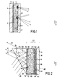
- FIG. 2 and 3 there is schematically shown a sectional side elevation view of an EPID device 20 according to a preferred embodiment of the present invention.
- the electrophoretic display device 20 contains an electrophoretic cell element 22 (described below) and a light transmissive panel 24 that can receive illumination 26 and serve to cause total internal reflection of such illumination.
- the light transmissive panel 24 comprises, in this embodiment, an optical prism having first and second surfaces 28, 30 with the first prism surface 28 being adapted to receive illumination 26, which illumination is refracted towards the second prism surface 30 as shown.
- the illumination 26 is reflected at the interface between the colloidal suspension 60 and the second surface 30 (as indicated by arrows 32), i.e., total internal reflection of the illumination or light rays occurs, except at predetermined areas of the second surface 30, as indicated hereinafter.
- the cell element 22 comprises a light transmissive panel plate 34 having first and second major surfaces 36, 38, respectively, the plate 34 being disposed so that the first - ⁇ surface 36 thereof faces the second surface 30 of the light transmissive panel 24.
- the cell element 22 of the EPID device 20 includes, in addition to the flat panel 34, which can be of glass or transparent plastic of, e.g., about 1.5 mm thickness, a plurality of parallel light transmitting conductive electrodes 44 disposed at the first major surface 36 of the panel 34, an insulating layer 48, a plurality of light transmitting electrodes 50, a colloidal suspension 60, and a light transmissive electrode 70, as described in detail below.
- the conductive electrodes 44 serve as column electrodes and can be composed of, for example, indium oxide typically applied to the panel 34 by means of sputtering.
- the column electrodes 44 are typically 300 nm. thick and have a width of 2.5 mm and their length depends upon the extent and size of the display device itself.
- the panel 34 and the column electrodes 44 are covered with the light transmissive insulating layer 48 that can be, for example, a photoresist or other dielectric material, and the insulating layer 48 is, e.g., from 5 to 50 / um thick and applied by a dip coating process.
- the electrodes 50 serve as row electrodes (which preferably are of transparent material, such as tin oxide or indium oxide, for example) are disposed at the available surface of the insulating layer 48 in the form of parallel strips extending transversely to the column electrodes 44.
- the row electrodes 50 can be of aluminium instead of transparent material so long as transparent areas are available for light to be transmitted through the cell, and can be formed by vacuum evaporation.
- Electrodes 50 are separated, at least in part, from the column electrodes 44 by the insulating layer 48.
- either of the row or column electrodes can be light opaque so long as at least a major portion of the cell area is light transmissive so as to permit light to pass therethrough.
- the row electrodes 50 can have a thickness of about 70 nmo and a width of about 2.5 mm.
- the interelectrode spacing 52 of the row electrodes 50 can be similar to that of the column electrodes 44, i.e., from 25-100 / um.
- the row electrodes 50 and insulating layer 48 are patterned as described in the above European Patent Application 0,002,094 and have minute pockets or holes (not shown) which extend down to the column electrodes 44. While this form of electrode arrangement is preferred, other electrode systems can be used in the present invention, e.g., a simple patterned electrode system such as a seven-segment numeric system.
- the above disclosed holes (not shown) of the row electrodes 50 and insulating layer 48 extend completely through the respective row electrodes 50 and insulator material 48, and expose the column electrodes 44 to the electrophoretic fluid 60, so that the row electrodes 50 serve as a control grid.
- the holes therefore, form pockets or cavities which serve as physical wells into which the pigment particles 76 are able to migrate, depending upon the electric field present.
- the holes can cover at least 50% and more typically 60-70% of the row electrode surface.
- An exemplary electrical configuration for operation of a display cell is that described in the above EP-PA 0,002,094 shown in highly schematic form.
- the continuous electrode 70 is grounded, although in other operation modes, a positive or negative voltage may be applied to the continuous electrode 70.
- First and second ones of the column electrodes 44 are connected to respective first and second switches, the row electrodes 50 being connected to other sources of potential.
- the colloidal particles 76 will be attracted to or repelled from the continuous electrode 70 or the column electrodes 44, as the case may be thereby forming the pattern for the desired image in the appropriate regions of the cell 20.
- light is coupled into the cell as detailed, below.
- the panel or prism 24 is provided opposite the second panel 34 and the plane major surface 30 of the first panel 24, which surface 30 faces the second panel 34, is coated with the electrode layer 70.
- the electrode 70 is preferred to be a continuous transparent electrode layer and can be, e.g., an optically thin layer of indium oxide adherent to the prism 24 and applied by the process of sputtering. Where the electrode layer 70 is not optically thin, its index of refraction influences the operation of the device and must be taken into consideration.
- the spacing between the continuous electrode 70 (Fig. 2) and the control electrodes 44, 50 can be approximately 40 / um.
- the end portions 72 between panels 24 and 34 are sealed (shown in Fig. 2) so that a fluid may be contained therebetween.
- the region between the column electrodes 44 and the continuous electrode 70 is filled with an "electrophoretic fluid", such as a colloidal suspension 60 comprised of a dielectric fluid 68, such as, e.g., a mixture of xylene and perchlorethylene, and transparent or coloured particles 76 homogeneously dispersed therein. These particles 76 can be transparent or can be pigmented, so long as they are light transmitting.
- This suspension 60 is more generally referred to throughout the specification as an "electrophoretic fluid”. All particles 76 in the suspension 60 have a charge of one polarity which is achieved by the addition of charging agents to the liquid with some examples of suitable agents being an amine attached to a polymeric hydrocarbon chain.
- ⁇ c is the critical angle
- the angle of incidence ⁇ i which is defined as the angle between a light ray and a normal 66 to the interface between the colloidal suspension and the panel or prism 24, should exceed the critical angle ⁇ c for the fluid 68 but not ⁇ c for the particles 76, in order for satisfactory light coupling to occur between the panel or prism 24, and the colloidal suspension 60.
- the angle of reflection is designated in the figures as ⁇ r .
- the prism 24 can don a refractive index of about 1.7, while the colloidal particles 76 can have a refractive index of about 2.0 and the insulating fluid 68 can have a refractive index of about 1.5. It is important that the insulating fluid 68 of the cell always have a refractive index less than that of the prism 24 and that refractive index for the colloidal particles 76 be such that the angle of incidence not exceed ⁇ c so as to achieve the desired light coupling by the particles 76, as described below.
- FIG. 2 The visual effects of the EPID operation are shown in Fig. 2, where the front side 38 of the EPID device is used for display, as is shown by the placement of the observer, the back side, at which the prism is located, not providing an image.
- the observer views through transparent panel 34 the displayed image which is composed of the various light rays coupled into the colloidal suspension 60 by the colloidal particle clusters 80 attracted to the continuous electrode 70 by the electrical addressing system comprising the various electrodes 44, 50, 70. Since the electrophoretic fluid 68 is transparent the light coupled by the colloidal particle aggregrates or clusters 80 passes therethrough and through the transparent electrodes 50, 44 and insulating layer 48, to the observer.
- the colloidal particles 76 do not materially aggregrate in the region of the transparent electrode 50 and insulating layer 48 so the observer 1 sees light transmitted through the cell from the areas of the colloidal particle clusters 80. Those areas of the continuous electrode 70 that are substantially free of aggregrates of the particles 76 do not couple the incident illumination at the colloid-plate interface at electrode 70 into the colloidal suspension 60 so that no significant amount of light is transmitted at these areas, which cause corresponding parts of the image to be dark. No light is transmitted at these parts because the fluid 68 has a refractive index sufficiently lower than the prism 24 so that ⁇ i > ⁇ c .
- Light coupling by the particles 76 is achieved because they have an index of refraction sufficiently high compared to the index of refraction of the prism so that ⁇ i ⁇ ⁇ c .
- a light colored yellow pigment is used.
- the display cell possesses "memory" since the pigment particles remain on or adjacent to the electrode 70, when the applied voltages are removed, due to electrical, chemical and van der Waals forces.
- various arrangements employing the various embodiment of the present invention can be utilized, e.g., one in which a number of arranged prisms, such as prism 24 in Fig. 2, are disposed on the display cell in the place of a single larger prism, each of the arranged prisms functioning in the same way as prism 24.
- the electrophoretic display system 100 (Fig. 4) comprises an electrophoretic cell element 22 comparable to that of the embodiment shown in Fig. 2, with corresponding elements of the embodiments of Fig. 2 and 4 identically numbered.
- the present system comprises a second panel 102 which has a first surface 109 that has a general profile of a sawtooth and an opposite second surface 104 that is substantially flat.
- a continuous electrode 106 whose profile generally resembles that of the surface 109, is disposed at the first surface 109, and the refractice index relationships above described with regard to the embodiment of Fig. 2 apply to the present embodiment, as does the relationship for the critical angle ⁇ c .
- the mode of operation of the system 100 is generally the same as that for the system of Fig. 2. Specifically, the electrode potentials are applied so that particle aggregrates 80 are formed at the desired areas of the continuous electrode 106, as shown in Fig. 4.
- the angle of incidence ⁇ i at the interface between the panel 102 and the colloidal suspension is such that total internal reflection occurs at those areas 108 of the interface that are substantially free of particle aggregrates and the reflected light is retroreflected out of the panel 102, and such that light coupling occurs at other areas 110 of the interface at which colloidal particle aggregrates 80 are located.
- the light coupling precludes total internal reflection at these other interface areas 110, and light passes through the cell to the observer. Those areas 108 at which total internal reflection occurs will appear as dark areas of the image and the light transmitted through the cell provides the light areas.
- the second panel 130 of the system that is employed with a cell element 22 comprises plane parallel first and second major surfaces 132, 134, with the continuaus electrode 70 of the cell element located at the first surface 134.
- a light-receiving third surface 138 is angularly disposed with respect to the major surfaces to provide edge lighting effects where light entering surface 138 is trapped by total internal reflection within panel 130, except as described hereinafter.
- Illumination impinging upon surface 138 enters the panel 130, where it is reflected as shown between the surface 134 at the interface between the plate 130 and the suspension 60, on the one hand, and the surface 132 between the plate 130 and air, on the other hand.
- the surface 132 may be provided with an opaque layer, e.g., felt cloth or black plastic.
- Light is coupled into the suspension 60 at those interface areas 148 at which colloidal particle clusters 80 are formed and is reflected from other interface areas 150 substantially free of the coupling colloidal particles.
- the coupled light passes through the cell to the observer, as described above, with no light emanating from the cell at those regions 150 which are free of the clusters 80, hence providing a light and dark image of the information written into the cell.
- the areas 148 having the clusters 80 or the other areas 150 without such clusters can be considered the "writing" embodying the displayed information.
- the projection system provided with an electrophoretic image display device may be constructed as illustrated in Fig. 6.
- a light source 160 is collimated by collimating lens 161 to a totally internally reflecting (TIR) prism 162 having the total reflecting surface 164 interfacing with an EPID type cell 170.
- the light reflected from the reflecting surface 164 of the TIR prism 162 is thereafter directed by way of mirror 165 through a projecting lens 166 onto a viewing screen 167.
- the EPID type cell 170 comprises a construction having a thin light transmissive electrode 176 disposed at the total internal reflecting surface 164 of the prism 162.
- a further electrode structure 171 is spaced from the first electrode 176 and a colloidal suspension of electrophoretic particles 172 is provided in an insulating liquid 173 in the space between the electrode structures 176 and 171.
- a light transmissive plate 174 is disposed adjacent to the electrode structure 171.
- Electrode structures 176 and 171 can cause transport of the electrophoretic particles172 in the insulating liquid 173 onto the surface of either of the electrode structures.
- the transport of the electrophoretic particles 172 may be in image-wise fashion at selected regions or areas of the electrode surface.
- the deposition 175 of the electrophoretic particles at the prism-liquid interface or surface 164 frustrates total internal reflection of the prism 162 at those regions.-Consequently, light will be scattered into the EPID cell at the regions 175 and will appear as dark areas on the viewing screen 167 since very little reflected light is projected to the screen 167 from these regions.
- the display device by applying appropriate voltages on the electrode structures 176 and 171 of the EPID type cell, images can be formed which are projected to the viewing screen 167. Because the particles 175 may be maintained at the surface 22 by way of electrical, chemical, and/or van der Waals forces even after the voltage applied to the electrodes is removed, then the display device exhibits an inherent memory. Removal of the electrophoretic particles from the aggregrated regions can be by way of the application of an appropriate counter force.
- a scanning laser may be utilised to write information into the EPID type cell.
- all of the electrophoretic particles are first broughtto the surface electrode structure 171 by applying a voltage of appropriate polarity.
- a small reverse voltage is then applied such that the particles remain attached to the surface, but when the scanning laser beam breaks the van der Waal's type bond between the particles and the surface, the freed particles will move to the TIR-electrode surface 164, i.e. the prism-liquid interface.
- the cell can be erased by the application of the same initial voltage pulse.
- all of the electrophoretic particles may be attracted to one surface, as above where the voltage is then removed, and an information writing instrument 180 (Fig. 6), such as an electrostatic pencil writes information by hand onto the cell surface 174.
- an information writing instrument 180 Fig. 6
- electrostatic pencil 180 repels particles to the opposite surface 176, or the TIR-interface.
- all of the particles may be initially attracted to the electrode 176 (with the subsequent removal of the voltage, as above), and then the writing of the information with the electrostatic pencil 180 would attract the particles away from the TIR surface to the electrode structure 171. Reversal of the charge on the electrostatic pencil would permit local erasure.
Landscapes
- Physics & Mathematics (AREA)
- Nonlinear Science (AREA)
- General Physics & Mathematics (AREA)
- Optics & Photonics (AREA)
- Health & Medical Sciences (AREA)
- Life Sciences & Earth Sciences (AREA)
- Molecular Biology (AREA)
- Chemical & Material Sciences (AREA)
- Chemical Kinetics & Catalysis (AREA)
- Electrochemistry (AREA)
- Electrochromic Elements, Electrophoresis, Or Variable Reflection Or Absorption Elements (AREA)
Applications Claiming Priority (4)
| Application Number | Priority Date | Filing Date | Title |
|---|---|---|---|
| US06/063,214 US4324456A (en) | 1979-08-02 | 1979-08-02 | Electrophoretic projection display systems |
| US63214 | 1979-08-02 | ||
| US63634 | 1979-08-02 | ||
| US06/063,634 US4218302A (en) | 1979-08-02 | 1979-08-02 | Electrophoretic display devices |
Publications (1)
| Publication Number | Publication Date |
|---|---|
| EP0023741A1 true EP0023741A1 (fr) | 1981-02-11 |
Family
ID=26743169
Family Applications (1)
| Application Number | Title | Priority Date | Filing Date |
|---|---|---|---|
| EP80200703A Withdrawn EP0023741A1 (fr) | 1979-08-02 | 1980-07-18 | Dispositif d'affichage électrophorétique d'image |
Country Status (2)
| Country | Link |
|---|---|
| EP (1) | EP0023741A1 (fr) |
| CA (1) | CA1152617A (fr) |
Cited By (16)
| Publication number | Priority date | Publication date | Assignee | Title |
|---|---|---|---|---|
| WO1982002961A1 (fr) * | 1981-02-24 | 1982-09-02 | Bassett Peter John | Dispositif d'affichage |
| GB2139392A (en) * | 1983-05-05 | 1984-11-07 | Standard Telephones Cables Ltd | Display device |
| EP0186922A2 (fr) * | 1984-12-31 | 1986-07-09 | Koninklijke Philips Electronics N.V. | Configurations d'électrode pour un dispositif électrophorétique |
| EP0902314A2 (fr) * | 1997-08-16 | 1999-03-17 | Mannesmann VDO Aktiengesellschaft | Méthode et dispositif pour l'atténuation continue et homogène d'un flux lumineux guidé sur une trajectoire |
| WO1999063401A1 (fr) * | 1998-06-05 | 1999-12-09 | Lear Automotive Dearborn, Inc. | Retroviseur a attenuation |
| WO2000010048A1 (fr) * | 1998-08-13 | 2000-02-24 | The University Of British Columbia | Affichage d'images base sur une reflexion interne totale contrecarree |
| WO2000075720A2 (fr) * | 1999-06-02 | 2000-12-14 | The University Of British Columbia | Commande de transition de phase a indice eleve par electrophorese de la reflexion totale interne dans des afficheurs d'images a reflectivite variable et efficacite elevee |
| US6304365B1 (en) | 2000-06-02 | 2001-10-16 | The University Of British Columbia | Enhanced effective refractive index total internal reflection image display |
| US6384979B1 (en) | 2000-11-30 | 2002-05-07 | The University Of British Columbia | Color filtering and absorbing total internal reflection image display |
| US6437921B1 (en) | 2001-08-14 | 2002-08-20 | The University Of British Columbia | Total internal reflection prismatically interleaved reflective film display screen |
| US6452734B1 (en) | 2001-11-30 | 2002-09-17 | The University Of British Columbia | Composite electrophoretically-switchable retro-reflective image display |
| US6574025B2 (en) | 1997-09-04 | 2003-06-03 | The University Of British Columbia | Optical switching by controllable frustration of total internal reflection |
| US6865011B2 (en) | 2002-07-30 | 2005-03-08 | The University Of British Columbia | Self-stabilized electrophoretically frustrated total internal reflection display |
| US6885496B2 (en) | 2002-03-04 | 2005-04-26 | The University Of British Columbia | Wide viewing angle reflective display |
| US7164536B2 (en) | 2005-03-16 | 2007-01-16 | The University Of British Columbia | Optically coupled toroidal lens:hemi-bead brightness enhancer for total internal reflection modulated image displays |
| WO2008032248A1 (fr) * | 2006-09-12 | 2008-03-20 | Koninklijke Philips Electronics N.V. | Guide de lumière contrôlable |
Citations (11)
| Publication number | Priority date | Publication date | Assignee | Title |
|---|---|---|---|---|
| AT218585B (de) * | 1957-10-19 | 1961-12-11 | Agfa Ag | Verfahren und Vorrichtung zur Lichtsteuerung |
| AT223670B (de) * | 1959-12-01 | 1962-10-10 | Agfa Ag | Einrichtung zur Lichtsteuerung |
| US3257903A (en) * | 1960-11-21 | 1966-06-28 | Alvin M Marks | Electrically responsive light controlling devices employing suspended dipole particles and shear forces |
| US3668106A (en) * | 1970-04-09 | 1972-06-06 | Matsushita Electric Ind Co Ltd | Electrophoretic display device |
| US3728007A (en) * | 1971-05-27 | 1973-04-17 | Scm Corp | Reflective type liquid crystal display device having improved optical contrast |
| GB1330089A (en) * | 1970-09-09 | 1973-09-12 | Marks A M | Dipolar electro-optic light controlling device and method |
| DE2509867A1 (de) * | 1974-03-06 | 1975-09-11 | Commissariat Energie Atomique | Vorrichtung zur schaustellung von zeichen |
| DE2723483A1 (de) * | 1976-05-20 | 1977-11-24 | Ebauches Sa | Passive elektro-optische anzeige |
| CH600470A5 (fr) * | 1976-11-09 | 1978-06-15 | Bbc Brown Boveri & Cie | |
| DE2726628B2 (de) * | 1976-06-30 | 1979-04-12 | International Business Machines Corp, Armonk, N.Y. (V-StA.) | Anzeigetafel |
| EP0002094A2 (fr) * | 1977-11-23 | 1979-05-30 | North American Philips Corporation | Affichage électrophorétique à adressage matriciel |
-
1980
- 1980-07-18 EP EP80200703A patent/EP0023741A1/fr not_active Withdrawn
- 1980-07-24 CA CA000356899A patent/CA1152617A/fr not_active Expired
Patent Citations (11)
| Publication number | Priority date | Publication date | Assignee | Title |
|---|---|---|---|---|
| AT218585B (de) * | 1957-10-19 | 1961-12-11 | Agfa Ag | Verfahren und Vorrichtung zur Lichtsteuerung |
| AT223670B (de) * | 1959-12-01 | 1962-10-10 | Agfa Ag | Einrichtung zur Lichtsteuerung |
| US3257903A (en) * | 1960-11-21 | 1966-06-28 | Alvin M Marks | Electrically responsive light controlling devices employing suspended dipole particles and shear forces |
| US3668106A (en) * | 1970-04-09 | 1972-06-06 | Matsushita Electric Ind Co Ltd | Electrophoretic display device |
| GB1330089A (en) * | 1970-09-09 | 1973-09-12 | Marks A M | Dipolar electro-optic light controlling device and method |
| US3728007A (en) * | 1971-05-27 | 1973-04-17 | Scm Corp | Reflective type liquid crystal display device having improved optical contrast |
| DE2509867A1 (de) * | 1974-03-06 | 1975-09-11 | Commissariat Energie Atomique | Vorrichtung zur schaustellung von zeichen |
| DE2723483A1 (de) * | 1976-05-20 | 1977-11-24 | Ebauches Sa | Passive elektro-optische anzeige |
| DE2726628B2 (de) * | 1976-06-30 | 1979-04-12 | International Business Machines Corp, Armonk, N.Y. (V-StA.) | Anzeigetafel |
| CH600470A5 (fr) * | 1976-11-09 | 1978-06-15 | Bbc Brown Boveri & Cie | |
| EP0002094A2 (fr) * | 1977-11-23 | 1979-05-30 | North American Philips Corporation | Affichage électrophorétique à adressage matriciel |
Non-Patent Citations (1)
| Title |
|---|
| IEEE Transactions on Electron Devices, Vol. ED-24, No. 7, July 1977, New York * Pages 827 - 834 * * |
Cited By (23)
| Publication number | Priority date | Publication date | Assignee | Title |
|---|---|---|---|---|
| WO1982002961A1 (fr) * | 1981-02-24 | 1982-09-02 | Bassett Peter John | Dispositif d'affichage |
| GB2139392A (en) * | 1983-05-05 | 1984-11-07 | Standard Telephones Cables Ltd | Display device |
| EP0186922A2 (fr) * | 1984-12-31 | 1986-07-09 | Koninklijke Philips Electronics N.V. | Configurations d'électrode pour un dispositif électrophorétique |
| EP0186922A3 (en) * | 1984-12-31 | 1988-05-04 | N.V. Philips' Gloeilampenfabrieken | Electrode configurations for electrophoretic device |
| EP0902314A2 (fr) * | 1997-08-16 | 1999-03-17 | Mannesmann VDO Aktiengesellschaft | Méthode et dispositif pour l'atténuation continue et homogène d'un flux lumineux guidé sur une trajectoire |
| EP0902314A3 (fr) * | 1997-08-16 | 2000-01-05 | Mannesmann VDO Aktiengesellschaft | Méthode et dispositif pour l'atténuation continue et homogène d'un flux lumineux guidé sur une trajectoire |
| US6574025B2 (en) | 1997-09-04 | 2003-06-03 | The University Of British Columbia | Optical switching by controllable frustration of total internal reflection |
| WO1999063401A1 (fr) * | 1998-06-05 | 1999-12-09 | Lear Automotive Dearborn, Inc. | Retroviseur a attenuation |
| WO2000010048A1 (fr) * | 1998-08-13 | 2000-02-24 | The University Of British Columbia | Affichage d'images base sur une reflexion interne totale contrecarree |
| KR100414034B1 (ko) * | 1998-08-13 | 2004-01-07 | 더 유니버시티 오브 브리티쉬 콜롬비아 | 화상 디스플레이 장치 및 화상 디스플레이 방법 |
| WO2000075720A2 (fr) * | 1999-06-02 | 2000-12-14 | The University Of British Columbia | Commande de transition de phase a indice eleve par electrophorese de la reflexion totale interne dans des afficheurs d'images a reflectivite variable et efficacite elevee |
| WO2000075720A3 (fr) * | 1999-06-02 | 2001-09-07 | Univ British Columbia | Commande de transition de phase a indice eleve par electrophorese de la reflexion totale interne dans des afficheurs d'images a reflectivite variable et efficacite elevee |
| US6304365B1 (en) | 2000-06-02 | 2001-10-16 | The University Of British Columbia | Enhanced effective refractive index total internal reflection image display |
| WO2001092980A3 (fr) * | 2000-06-02 | 2002-12-19 | Univ British Columbia | Affichage d'image par reflexion interne totale a indice accru de refraction effective |
| WO2001092980A2 (fr) * | 2000-06-02 | 2001-12-06 | The University Of British Columbia | Affichage d'image par reflexion interne totale a indice accru de refraction effective |
| US6384979B1 (en) | 2000-11-30 | 2002-05-07 | The University Of British Columbia | Color filtering and absorbing total internal reflection image display |
| US6437921B1 (en) | 2001-08-14 | 2002-08-20 | The University Of British Columbia | Total internal reflection prismatically interleaved reflective film display screen |
| US6452734B1 (en) | 2001-11-30 | 2002-09-17 | The University Of British Columbia | Composite electrophoretically-switchable retro-reflective image display |
| US6885496B2 (en) | 2002-03-04 | 2005-04-26 | The University Of British Columbia | Wide viewing angle reflective display |
| US6891658B2 (en) | 2002-03-04 | 2005-05-10 | The University Of British Columbia | Wide viewing angle reflective display |
| US6865011B2 (en) | 2002-07-30 | 2005-03-08 | The University Of British Columbia | Self-stabilized electrophoretically frustrated total internal reflection display |
| US7164536B2 (en) | 2005-03-16 | 2007-01-16 | The University Of British Columbia | Optically coupled toroidal lens:hemi-bead brightness enhancer for total internal reflection modulated image displays |
| WO2008032248A1 (fr) * | 2006-09-12 | 2008-03-20 | Koninklijke Philips Electronics N.V. | Guide de lumière contrôlable |
Also Published As
| Publication number | Publication date |
|---|---|
| CA1152617A (fr) | 1983-08-23 |
Similar Documents
| Publication | Publication Date | Title |
|---|---|---|
| US4218302A (en) | Electrophoretic display devices | |
| US4324456A (en) | Electrophoretic projection display systems | |
| EP0023741A1 (fr) | Dispositif d'affichage électrophorétique d'image | |
| US6064784A (en) | Electrophoretic, dual refraction frustration of total internal reflection in high efficiency variable reflectivity image displays | |
| US5959777A (en) | Passive high efficiency variable reflectivity image display device | |
| US6437921B1 (en) | Total internal reflection prismatically interleaved reflective film display screen | |
| KR100466583B1 (ko) | 강화된 실효굴절률 내부전반사 이미지 디스플레이 및이미지 디스플레이 방법 | |
| US8040591B2 (en) | Ionic electrophoresis in TIR-modulated reflective image displays | |
| EP0542924B1 (fr) | Affichage optique | |
| US9939706B2 (en) | Displaced porous electrode for frustrating TIR and returning light through exit pupil | |
| US9122005B2 (en) | Electrowetting retroreflector devices, systems, and methods | |
| US3947091A (en) | Reflective display apparatus | |
| US20080002247A1 (en) | Display unit | |
| US20080198292A1 (en) | Lighting Device | |
| KR20030017661A (ko) | 꺾여진 내부 전반사에 기초한 디스플레이 디바이스 | |
| CN102693046A (zh) | 互动显示设备中的悬停检测 | |
| GB2306229A (en) | Diffusely reflective display cell | |
| KR20020010685A (ko) | 고효율 가변 반사 이미지 디스플레이에 있어서 내부전반사의 전기영동과 고굴절률 및 상변화 제어를 이용하는반사 이미지 디스플레이장치 및 그 방법 | |
| US4385805A (en) | Liquid crystal lens display system | |
| US20150070752A1 (en) | Method and system for perforated reflective film display device | |
| JP3360851B2 (ja) | 液晶表示装置 | |
| US4158201A (en) | Flat electro optic display panel and method of using same | |
| US20090161368A1 (en) | Display | |
| KR20050086555A (ko) | 표시 장치 및 그 구동 방법 | |
| US20050179619A1 (en) | Electro-optical display device |
Legal Events
| Date | Code | Title | Description |
|---|---|---|---|
| PUAI | Public reference made under article 153(3) epc to a published international application that has entered the european phase |
Free format text: ORIGINAL CODE: 0009012 |
|
| AK | Designated contracting states |
Designated state(s): CH DE FR GB IT NL |
|
| 17P | Request for examination filed |
Effective date: 19810216 |
|
| STAA | Information on the status of an ep patent application or granted ep patent |
Free format text: STATUS: THE APPLICATION IS DEEMED TO BE WITHDRAWN |
|
| RAP1 | Party data changed (applicant data changed or rights of an application transferred) |
Owner name: N.V. PHILIPS' GLOEILAMPENFABRIEKEN |
|
| 18D | Application deemed to be withdrawn |
Effective date: 19820716 |
|
| RIN1 | Information on inventor provided before grant (corrected) |
Inventor name: SEYMOUR, R.J. Inventor name: DALISA, A.L. |