EP0023112B1 - Ventil, insbesondere für einen Förderrohrstrang - Google Patents
Ventil, insbesondere für einen Förderrohrstrang Download PDFInfo
- Publication number
- EP0023112B1 EP0023112B1 EP80302332A EP80302332A EP0023112B1 EP 0023112 B1 EP0023112 B1 EP 0023112B1 EP 80302332 A EP80302332 A EP 80302332A EP 80302332 A EP80302332 A EP 80302332A EP 0023112 B1 EP0023112 B1 EP 0023112B1
- Authority
- EP
- European Patent Office
- Prior art keywords
- valve
- funnel
- liner
- valve member
- prong
- Prior art date
- Legal status (The legal status is an assumption and is not a legal conclusion. Google has not performed a legal analysis and makes no representation as to the accuracy of the status listed.)
- Expired
Links
- 241000282472 Canis lupus familiaris Species 0.000 claims description 33
- 239000012530 fluid Substances 0.000 claims description 19
- 230000004044 response Effects 0.000 claims description 3
- 238000004891 communication Methods 0.000 claims description 2
- 230000001419 dependent effect Effects 0.000 claims 1
- 210000002445 nipple Anatomy 0.000 description 13
- 238000012360 testing method Methods 0.000 description 10
- 230000015572 biosynthetic process Effects 0.000 description 4
- 230000008859 change Effects 0.000 description 2
- 238000010276 construction Methods 0.000 description 2
- 230000009471 action Effects 0.000 description 1
- 230000009286 beneficial effect Effects 0.000 description 1
- 239000002131 composite material Substances 0.000 description 1
- 230000008878 coupling Effects 0.000 description 1
- 238000010168 coupling process Methods 0.000 description 1
- 238000005859 coupling reaction Methods 0.000 description 1
- 230000003111 delayed effect Effects 0.000 description 1
- 238000009826 distribution Methods 0.000 description 1
- 238000009434 installation Methods 0.000 description 1
- 238000004519 manufacturing process Methods 0.000 description 1
- 239000000463 material Substances 0.000 description 1
- 238000000034 method Methods 0.000 description 1
- 238000012856 packing Methods 0.000 description 1
- 239000013618 particulate matter Substances 0.000 description 1
- 239000003208 petroleum Substances 0.000 description 1
- 238000007789 sealing Methods 0.000 description 1
- 230000007480 spreading Effects 0.000 description 1
- 238000003892 spreading Methods 0.000 description 1
- 230000003068 static effect Effects 0.000 description 1
- 238000012956 testing procedure Methods 0.000 description 1
- 210000001364 upper extremity Anatomy 0.000 description 1
- 238000003466 welding Methods 0.000 description 1
Images


Classifications
-
- E—FIXED CONSTRUCTIONS
- E21—EARTH OR ROCK DRILLING; MINING
- E21B—EARTH OR ROCK DRILLING; OBTAINING OIL, GAS, WATER, SOLUBLE OR MELTABLE MATERIALS OR A SLURRY OF MINERALS FROM WELLS
- E21B34/00—Valve arrangements for boreholes or wells
- E21B34/06—Valve arrangements for boreholes or wells in wells
- E21B34/14—Valve arrangements for boreholes or wells in wells operated by movement of tools, e.g. sleeve valves operated by pistons or wire line tools
Definitions
- the present invention relates to valves.
- the present invention relates to valves which may form a part of a tubing string.
- the valve is supported in removable fashion in a landing nipple so that it may be removed after testing procedures are completed.
- the valve is designed to receive a pressure conducting prong which may be connected to the surface through a suitable electric line to transmit signals corresponding to the pressure of the fluid at the valve and thus the valve may be referred to in this and related applications as a transducer fitting.
- the porting through which fluid flows in the valve member of a sleeve valve preferably is so small that the 0-ring cannot be extruded into the porting and thus the 0-ring is protected against damage.
- the porting preferably is large enough to permit acceptable flow of fluid through the porting.
- a valve comprising a tubular valve body with a side port in said body and a valve member which is movable to control the flow through said port, characterised in that a pair of circumferential seals are provided on the inner wall of said tubular body at axially spaced apart locations, one on each side of said port, and in that the valve member includes a tubular funnel and a tubular liner arranged in end to end abutment the valve member being movable axially to pass said abutment across one of said seals, means maintaining the funnel and liner in coaxial alignment and means both holding said funnel and liner together with no more than a slight space therebetween while the juncture between said funnel and liner passes over one of said seals as the valve moves between open and closed positions, and permitting said funnel and liner to move apart in response to the valve member moving to the open position.
- a valve comprising a tubular valve body with a side port in said body, and a valve member which is movable to control the flow through said port, characterised in that a pair of circcumferential seals are provided on the inner wall of said tubular body at axially spaced apart locations, one on each side of the port, and in that the valve member includes a tubular funnel and a tubular liner arranged in end to end abutment, the valve member being movable axially to pass said abutment across one of said seals, means maintaining the funnel and liner in coaxial alignment, and arm means having one end attached to said funnel and an intermediate section pivotal about the end of the liner remote from the funnel and the other end alternatively engaging a land in the body to hold the liner and funnel close to each other, and moving into a groove in the body to permit pivoting of said arm means to allow the juncture between the funnel and liner to open up.
- a valve comprising a tubular valve body with a side port in said body, and a valve member which is movable to control the flow through said port, characterised in that a pair of circumferential seals are provided on the inner wall of said tubular body at axially spaced apart locations, one on each side of the port, and in that the valve member includes a tubular funnel and a tubular liner arranged in end to end abutment, the valve member being movable axially to pass the abutment across one of said seals, means maintaining the funnel and liner in coaxial alignment, and in that collet means are carried by the valve member and have dogs which are in a retracted position when the dogs engage in a first groove in said body and are extended inwardly to engage an actuating prong when said dogs are engaged over a first land in said body, and in that arm means are provided, one end of said arm means being attached to the funnel and the other end having dogs for engaging a second land
- a prong may be utilized to open and close the valve in which dogs within the valve are moved between a prong engaging and prong releasing position in response to movement of the valve between open and closed positions.
- valve and prong is provided with a seal between the valve member and the prong and a flow passage in the prong so that fluid passing through the sleeve valve may be conducted to a pressure recording or transmitting device.
- Such a valve is preferably provided with a prong and automatic latching means between the sleeve valve and prong such that when the prong is withdrawn the sleeve valve automatically closes and traps in the sleeve valve and in the landing nipple thereabove a sample of formation fluid.
- the present invention thus provides a sleeve valve with a two-piece sleeve valve member in which the two members are in abutting relationship and are automatically held close to each other while the juncture between the two parts is passing over seals in the valve and which permits the two parts to move apart from each other after the seals have been cleared to reduce the tendency of seals to be damaged at the juncture between the two parts of the valve member as they are moving across the seals and to permit the two parts to open up under pressure of fluid being controlled to give an adequate size passageway for the fluid to flow through the valve.
- a valve according to the present invention may be moved between open and closed positions by moving a prong axially in the valve to move the valve member between open and closed positions and in which when the valve member is moved to closed position the prong is released to permit it to be withdrawn from the valve; the prong being latched to the valve member while the valve member is in open position so that withdrawal of the prong automatically moves the valve member from open to closed position and then releases the prong.
- FIG. 1 there is shown a well having a casing 10 and standard surface equipment 11 at the top of the well.
- the casing and well are shown to be perforated at 12 in the region of the formation to be tested.
- the test or production tubing 18 is shown to have a circulating valve 19, a cushion valve 21 and a seal unit 13 with the tailpipe of the seal unit in sealing engagement with the packer 14.
- the cushion valve may be utilized to support a column of fluid in the tubing which is released by opening of the cushion valve when the string engages the packer 14.
- the packer 14 seals off the producing formation and the foot sleeve valve 15 controls the flow through the foot sleeve and into the tubing.
- the landing nipple and transducer fitting provide for locating a transducer, such as a pressure sensing device, within the fitting to sense the pressure in the casing and below the packer 14. With this assembly, static pressure in the formation below the packer as well as build-up pressure can be recorded or transmitted to the surface through a suitable electric line and flow can be provided through the foot sleeve valve to test the flow characteristics of the well.
- the circulating valve is normally closed. Conditions may arise, however, when, it is desirable or imperative to provide for circulation between the casing- tubing annulus and the tubing.
- the circulating valve 19 may be quickly and readily opened to provide for such circulation.
- valve of this invention may be used in any desired setting. It was developed, however, to form a part of the testing system shown and its construction and operation will be explained in this setting. The invention, however, is not restricted to the system shown and the valve may be positioned other than in the relationship shown and may be used in any desired setting in which its functions would be beneficial.
- the transducer fitting or valve 17 is suspended from the landing nipple 16 which in turn is suspended from packer 14. Suitable landing nipples and locking mandrels are shown at page 5324 of the Composite Catalog of Oil- field Equipment and Services, 33rd Revision for 1978-1979.
- the valve of this invention may be attached to a locking mandrel and positioned in the nipple during running of the packer. In the alternative, the bore through the landing nipple may be left open and after the tubing string has been located the mandrel and transducer fitting may be run into and located in the landing nipple.
- a suitable prong may be run into the well to shift the valve 17 between the open and closed positions.
- the running tool for the locking mandrel may have an extension thereon carrying a suitable prong in the transducer fitting 17 to hold the valve in the desired open or closed position.
- the pulling tool for the locking mandrel may have a suitable prong thereon to hold the transducer fitting in the desired open or closed position during pulling of the locking mandrel and transducer fitting.
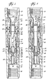
- the transducer fitting or valve 17 (see Figures 2 and 3) has an upper body section 22 and a lower body section 23 suitably threaded together by the thread and seal system indicated generally at 24.
- the upper end of the body is provided with threads 25 for coupling the transducer fitting to a locking mandrel so that mandrel and transducer fitting may be supported in the landing nipple 16.
- threads 26 are provided and it is preferred that a length of tubing be secured by the threads 26 to the lower end of the valve and that the bottom of the tubing be closed so that flow into the tubing can only enter through the transducer fitting.
- This length of tubing provides a basket or sump into which any particulate matter which may find its way into the tubing may fall through the transducer fitting and be collected.
- the locking mandrel on which the transducer fitting is run is provided with suitable packing to seal between the locking mandrel and the landing nipple 16 and thus with the bottom of the valve 17 closed flow is restricted to that permitted by the valve 17 or by the foot valve 15.
- the body of the valve includes a seal carrying fitting 27 having a flow port 28 extending radially therethrough and terminating in a distribution groove 29.
- the body 22 has a port 31 therein.
- the seal carrier 27 is positioned such that the port 28 and port 31 are aligned and the seal carrier 27 is then welded in place with the weld forming a seal between the body 22 and the seal carrier 27.
- the seal carrier 27 is provided on opposite sides of the port 28 with grooves 32 and 33. Suitable seals such as O-rings 34 and 35 are positioned in these grooves, extend circumferentially about the fitting 27 and straddle the flow port 28. The seals are of equal diameter so that pressure from port 28 is balanced and only friction need be overcome in shifting the valve member.
- a suitable valve member is provided by funnel 36 and liner 37.
- the valve member is tubular in form.
- the iuncture or abutment between the funnel 36 and liner 37 provides for flow from the exterior to the interior bore of the valve member when the valve is in open position.
- this juncture between the funnel and liner is held to very close tolerance as the juncture moves over the 0-ring 34.
- Means are provided for maintaining the liner and funnel in coaxial relationship. This may be any desired means. As shown in Figures 2 and 3, the juncture between the liner 37 and funnel 36 is not in a single plane but is stepped so that the liner and funnel each has two symetrically positioned teeth which interfit with each other. Thus, the funnel carries teeth 38 and 39 and the liner has co-operating teeth, one of which is shown at 41. The side walls of these step-like teeth are cut on radii of the valve member. Preferably they are cut to close tolerance so that when the funnel and liner are interfitting the opposing teeth of the funnel and liner will interengage and maintain the funnel and liner in coaxial alignment. As the funnel moves into the seal fitting 27, this fitting 27 will also tend to hold the funnel and liner in coaxial alignment.
- a prong such as the prong indicated generally at 42 in Figure 9 may be utilized to move the valve member between open and closed positions.
- the prong will customarily be run in the well, as upon a wireline, and will seat on the valve member. Seating may occur at the upper lip 43 of the funnel or at the shoulder 44 adjacent the bottom of the liner 37. In either event, the reduced diameter or groove section 45 just above the head 46 of the prong 42 will be positioned opposite a pair of opposing cutouts 47 in the liner 37.
- the valve member In order to detent the valve member in the closed position, and to provide for latching of the valve member to a prong such as prong 42, the valve member carries a suitable collet 48.
- This collet is shown in detail in Figures 7 and 8.
- the collet has inwardly and outwardly facing dogs 49 and 50 carried on the collet arms 51. These arms are in turn carried by collet arms 52.
- each collet arm 52 extends between two collet arms 51 on either side thereof and the collet arms 52 are interconnected at 53. This provides for resiliency in both the arms 51 and 52.
- the liner 37 has a circumferentially radially extending flange 54 which is engaged by the shoulder 55 internally of the collet.
- the seal carrier 27 is provided with a groove 56 and immediately therebelow a land 57.
- This groove and land co-operate with the dog 50 on the collet and when the valve is in the closed position as shown, the dog 50 lies within the groove 56.
- the dog 50 engages the land 57 causing the collet arms to move inwardly and move the dog portion 49 into a position to engage shoulder 60 between the groove 45 and head 46 on the prong 42 ( Figure 9).
- the prong is moved downwardly it shifts the sleeve valve from closed to open position against the resistance of the detent action of the collet.
- the collet dogs 49 engage the prong and hold the prong and valve member interengaged until the valve member is again shifted upwardly to the closed position, at which time the dogs release the prong and permits its withdrawal.
- Arm means are provided for holding the funnel and liner together and for holding the funnel and liner very close to each other as their juncture passes over 0-ring 34 and permitting this juncture point to open up under pressure of the fluid in the system when the valve is open.
- the arm means indicated generally at 58 is best seen in Figures 5 and 6, taken in conjunction with Figures 2 and 3.
- Arm means 58 is provided with four finger-like upper extremities 59.
- the collet arms 51 have a small circumferential dimension leaving a wide space on opposite sides of these fingers.
- the two pairs of fingers 59 extend in these spaces.
- the fingers 59 have circumferentially extending, inwardly projecting flanges 61 which mate with groove 62 in the funnel ( Figures 2 and 3).
- the square shouldered relationship between the upwardly facing shoulder on the funnel and the downwardly facing shoulder on the flange 61 of the arm means permits the arm to place a downward pull on the funnel 36.
- the chamfered shoulder 63 on the funnel and the mirror image shoulder 64 on the arm means 58 permit all of the assembly except the funnel to be installed in the body from the lower end, and the funnel to be installed in the body from the upper end.
- a shoulder 65 is provided which confronts the lower end 66 of the tubular liner.
- the juncture of the two shoulders 65 and 66 is spaced radially inwardly a substantial distance from the fingers 59 and this juncture acts as a fulcrum or pivot about which the arm means 58 may rotate to change the relationship of the funnel and liner to each other.
- the arm means will bend in the area 67 to change this relationship.
- the arm means 58 is slotted at its lower end at 68 so that the several lower fingers 69 may move radially.
- the lower body section 23 has a land 71 and an adjacent groove 72.
- the lower fingers 69 of the arm means 58 are provided with dogs 73 which engage the land 71 during the time that the juncture between the funnel and the liner are moving over the seal 34. While the dogs 73 are in engagement with the land 71 they are held against radial outer movement and the dimensional relationship of the parts are such that by exerting force on the fulcrum parts 65 and 66 the arm means holds the funnel and liner very close to each other. When the valve member is shifted downwardly the funnel and liner are held close together until their juncture passes over the 0-ring 34.
- the dogs 73 move into the groove 72 and are no longer functional to prevent spreading of the lower fingers 69 to permit slight upward movement of the upper fingers 59 relative to the tubular liner 37 and thus open up the gap between the tubular liner 37 and the funnel 36.
- the gap opens up to a spacing of several thousandths of an inch to permit the desired flow through port 28.
- the device is assembled by first welding the seal carrier 27 in the upper body 22. A space between the carrier and body permits fluid communication from above 0-ring 34 to below 0- ring 35 to prevent a fluid lock when running prong 42.
- the liner, collet and arm means are then assembled together and introduced into the bottom of housing 22.
- the funnel is then introduced from the upper end of body 22 and moved down over the flange 61 of the arm means until the flange engages in the groove 62 in the funnel.
- the two body parts may then be made up together and a plug introduced into the lower threaded section 26 of the body or a tubular extension with a suitable plug at its lower end may be made up in the threaded section 26.
- the body is then attached to a locking mandrel.
- transducer fitting The operation of the transducer fitting will be explained assuming that it is to be run after tubing has been installed. In this event the well would first have the packer 14 with the foot valve 15 and landing nipple 16 run into the well and secured in place by setting of the packer in any desired conventional manner.
- testing is to be delayed until some future time after the well is completed, it may be desirable to run a locking mandrel with a plug therein to plug the well at the packer. If so, when testing is to be commenced this locking mandrel and plug would be removed.
- tubing string 18 is run into the well and the tailpipe or lower end of the tubing string is sealingly engaged with the packer 14.
- the cushion valve 21 is opened by the weight of the tubing thereabove providing a clear unobstructed tubing.
- the packer and landing nipple have a bore therethrough to permit running of the desired tools.
- the locking mandrel has the transducer fitting 17 made up on the lower end thereof and the transducer fitting and locking mandrel and run in as a unit, as by wireline.
- the valve member may be securely held in either open or closed position during either running or pulling by providing a suitable prong on the bottom of the locking mandrel running tool.
- a prong such as that shown in Figure 9 but without the flow-way 74 and 0-rings 75 and 76 could be used.
- the transducer fitting may be utilized to collect samples or to convey fluid to a pressure recording or sending device to record pressure in the well.
- the prong 42 may have connected to its upper end either a recording device or a transducer attached to the surface through an electric line. The prong 42 will be run in the well and moved downwardly to force the valve member to the open position with the 0-rings 75 and 76 of the prong straddling the juncture between the funnel 36 and the liner 37.
- the O-rings 75 and 76 are of equal diameter so that forces due to pressure from port 28 are balanced and only friction need be overcome to run or pull the prong. Normally the weight of the prong is all that is necessary to seat the prong.
- valve member when the valve member moves downwardly to the open position flow may occur through port 28, the juncture between the funnel and liner, and into the flow-way 74 in the prong.
- the pressure may be conducted to a suitable transducer and the pressure continuously read at the surface or recorded in a suitable recording device connected to the prong.
- the collet dogs 49 While the prong is in place and the valve member is in the down position, the collet dogs 49 will latch the valve member to the prong.
- the dogs 73 overlie grooves 72 and well pressure will be exerted in opposite directions on the funnel 36 and the liner 37. This well pressure will urge the funnel and liner away from each other.
- the prong 42 After testing has been completed, the prong 42 will be withdrawn. As the prong moves upwardly, the collet dogs 49 engaging the prong head 46 will move the valve member to the up or closed position prior to the collet dogs 49 releasing the head 46 on the prong and permitting the prong to be withdrawn from the well.
- the transducer fitting and its associated locking mandrel may now be removed from the well. If it is desired to remove from the well a sample of fluid when the locking mandrel and transducer fitting are removed, the operating prong would first be run to open the valve and permit flow from the well into the transducer fitting and the locking mandrel. The valve would then be closed and a suitable prong run on the locking mandrel retrieving tool to fill the gap between the collet dogs 49 and lock the valve in the closed position. Then as the locking mandrel and transducer are brought to the surface, they will contain a sample of fluid at the bottom of the well at the time that the transducer was pulled. If it is desired that the sample be uncontaminated, a suitable seal can be provided between the prong and the bore through the locking mandrel.
- a sample can be brought to the surface with the pressure reading prong by providing a suitable chamber in conjunction with the passageway 74 and a back check valve to prevent loss of well fluid after the prong is withdrawn from the transducer fitting.
Landscapes
- Geology (AREA)
- Life Sciences & Earth Sciences (AREA)
- Engineering & Computer Science (AREA)
- Mining & Mineral Resources (AREA)
- Environmental & Geological Engineering (AREA)
- Fluid Mechanics (AREA)
- Physics & Mathematics (AREA)
- General Life Sciences & Earth Sciences (AREA)
- Geochemistry & Mineralogy (AREA)
- Quick-Acting Or Multi-Walled Pipe Joints (AREA)
- Fluid-Driven Valves (AREA)
- Magnetically Actuated Valves (AREA)
- Compressor (AREA)
Claims (9)
Applications Claiming Priority (2)
| Application Number | Priority Date | Filing Date | Title |
|---|---|---|---|
| US06/056,886 US4266614A (en) | 1979-07-12 | 1979-07-12 | Valve |
| US56886 | 1979-07-12 |
Publications (2)
| Publication Number | Publication Date |
|---|---|
| EP0023112A1 EP0023112A1 (de) | 1981-01-28 |
| EP0023112B1 true EP0023112B1 (de) | 1983-09-07 |
Family
ID=22007158
Family Applications (1)
| Application Number | Title | Priority Date | Filing Date |
|---|---|---|---|
| EP80302332A Expired EP0023112B1 (de) | 1979-07-12 | 1980-07-10 | Ventil, insbesondere für einen Förderrohrstrang |
Country Status (6)
| Country | Link |
|---|---|
| US (1) | US4266614A (de) |
| EP (1) | EP0023112B1 (de) |
| AU (1) | AU532508B2 (de) |
| CA (1) | CA1131559A (de) |
| DK (1) | DK301880A (de) |
| NO (1) | NO802085L (de) |
Families Citing this family (9)
| Publication number | Priority date | Publication date | Assignee | Title |
|---|---|---|---|---|
| US4289201A (en) * | 1979-08-20 | 1981-09-15 | Otis Engineering Corporation | Well test apparatus |
| US4596272A (en) * | 1984-02-27 | 1986-06-24 | Swagelok Company | Coupling |
| US4671540A (en) * | 1984-02-27 | 1987-06-09 | Swagelok Company | Coupling |
| FR2648863B1 (fr) * | 1989-06-23 | 1995-12-01 | Elf Aquitaine | Procede et dispositif de prelevement d'un echantillon de fluide de gisement |
| US5842517A (en) * | 1997-05-02 | 1998-12-01 | Davis-Lynch, Inc. | Anti-rotational cementing apparatus |
| US6702024B2 (en) | 2001-12-14 | 2004-03-09 | Cilmore Valve Co., Ltd. | Dual energized hydroseal |
| US7073590B2 (en) * | 2001-12-14 | 2006-07-11 | Gilmore Valve Co., Ltd. | Dual energized hydroseal |
| US10648290B2 (en) | 2014-05-18 | 2020-05-12 | Thru Tubing Solutions, Inc. | Sleeve shifting tool |
| US9500283B1 (en) | 2014-06-23 | 2016-11-22 | Redfish Rentals, Inc. | Foot valve apparatus |
Family Cites Families (7)
| Publication number | Priority date | Publication date | Assignee | Title |
|---|---|---|---|---|
| US3263752A (en) * | 1962-05-14 | 1966-08-02 | Martin B Conrad | Actuating device for valves in a well pipe |
| US3306365A (en) * | 1963-05-13 | 1967-02-28 | Baker Oil Tools Inc | Well bore testing and displacing valve apparatus |
| US3527297A (en) * | 1969-02-17 | 1970-09-08 | Jerry L Pinkard | Stage cementer |
| US3765443A (en) * | 1971-06-21 | 1973-10-16 | Schlumberger Technology Corp | Velocity sensitive safety valve mechanism |
| US3768556A (en) * | 1972-05-10 | 1973-10-30 | Halliburton Co | Cementing tool |
| US3848629A (en) * | 1972-10-31 | 1974-11-19 | Schlumberger Technology Corp | Low flow safety valve with pressure lock |
| US4049052A (en) * | 1976-04-05 | 1977-09-20 | Otis Engineering Corporation | Subsurface annulus safety valve |
-
1979
- 1979-07-12 US US06/056,886 patent/US4266614A/en not_active Expired - Lifetime
-
1980
- 1980-04-30 CA CA350,941A patent/CA1131559A/en not_active Expired
- 1980-05-07 AU AU58185/80A patent/AU532508B2/en not_active Ceased
- 1980-07-10 EP EP80302332A patent/EP0023112B1/de not_active Expired
- 1980-07-11 DK DK301880A patent/DK301880A/da not_active Application Discontinuation
- 1980-07-11 NO NO802085A patent/NO802085L/no unknown
Also Published As
| Publication number | Publication date |
|---|---|
| AU5818580A (en) | 1981-01-15 |
| AU532508B2 (en) | 1983-10-06 |
| EP0023112A1 (de) | 1981-01-28 |
| US4266614A (en) | 1981-05-12 |
| DK301880A (da) | 1981-01-13 |
| CA1131559A (en) | 1982-09-14 |
| NO802085L (no) | 1981-01-13 |
Similar Documents
| Publication | Publication Date | Title |
|---|---|---|
| US4830107A (en) | Well test tool | |
| US4583592A (en) | Well test apparatus and methods | |
| CN102016226B (zh) | 内部树帽和itc送入工具 | |
| US4280561A (en) | Valve | |
| EP0023399B1 (de) | Verfahren und Vorrichtung zum Untersuchen von Erdölbohrlöchern | |
| US4069865A (en) | Bottom hole fluid pressure communicating probe and locking mandrel | |
| CA1076955A (en) | Full flow bypass valve | |
| EP0121566A1 (de) | Im bohrloch auswechselbares innenausblasventil. | |
| NL8003062A (nl) | Cementeergereedschap. | |
| US4108243A (en) | Apparatus for testing earth formations | |
| EP0023112B1 (de) | Ventil, insbesondere für einen Förderrohrstrang | |
| US4258793A (en) | Oil well testing string bypass valve | |
| US3990511A (en) | Well safety valve system | |
| US4328866A (en) | Check valve assembly | |
| WO1998050675A1 (en) | Multi-gage blowout preventer test tool and method | |
| US20040055757A1 (en) | Locking apparatus with packoff capability | |
| CA1143279A (en) | Method and system for well testing | |
| US4506731A (en) | Apparatus for placement and retrieval of downhole gauges | |
| US4867237A (en) | Pressure monitoring apparatus | |
| EP0020155B1 (de) | Ventil mit Betätigungsvorrichtung für Bohrlöcher | |
| GB1583435A (en) | Oil well testing safety valve | |
| CA1165226A (en) | Well system | |
| US4582136A (en) | Method and apparatus for placement and retrieval of downhole gauges | |
| US4373583A (en) | Test-system | |
| EP0024214B1 (de) | Umleitungsventil für einen Apparat zum Untersuchen eines Bohrloches |
Legal Events
| Date | Code | Title | Description |
|---|---|---|---|
| PUAI | Public reference made under article 153(3) epc to a published international application that has entered the european phase |
Free format text: ORIGINAL CODE: 0009012 |
|
| AK | Designated contracting states |
Designated state(s): FR GB NL |
|
| 17P | Request for examination filed |
Effective date: 19810309 |
|
| GRAA | (expected) grant |
Free format text: ORIGINAL CODE: 0009210 |
|
| AK | Designated contracting states |
Designated state(s): FR GB NL |
|
| ET | Fr: translation filed | ||
| PGFP | Annual fee paid to national office [announced via postgrant information from national office to epo] |
Ref country code: FR Payment date: 19840621 Year of fee payment: 5 |
|
| PLBE | No opposition filed within time limit |
Free format text: ORIGINAL CODE: 0009261 |
|
| PLBE | No opposition filed within time limit |
Free format text: ORIGINAL CODE: 0009261 |
|
| STAA | Information on the status of an ep patent application or granted ep patent |
Free format text: STATUS: NO OPPOSITION FILED WITHIN TIME LIMIT |
|
| PGFP | Annual fee paid to national office [announced via postgrant information from national office to epo] |
Ref country code: NL Payment date: 19840731 Year of fee payment: 5 |
|
| 26N | No opposition filed | ||
| 26N | No opposition filed | ||
| PG25 | Lapsed in a contracting state [announced via postgrant information from national office to epo] |
Ref country code: NL Effective date: 19860201 |
|
| GBPC | Gb: european patent ceased through non-payment of renewal fee | ||
| NLV4 | Nl: lapsed or anulled due to non-payment of the annual fee | ||
| PG25 | Lapsed in a contracting state [announced via postgrant information from national office to epo] |
Ref country code: FR Free format text: LAPSE BECAUSE OF NON-PAYMENT OF DUE FEES Effective date: 19860328 |
|
| REG | Reference to a national code |
Ref country code: FR Ref legal event code: ST |
|
| PG25 | Lapsed in a contracting state [announced via postgrant information from national office to epo] |
Ref country code: GB Effective date: 19881118 |