EP0022897B1 - Wirbelschichtbett-Einspritzvorrichtung für Kohlevergasung - Google Patents
Wirbelschichtbett-Einspritzvorrichtung für Kohlevergasung Download PDFInfo
- Publication number
- EP0022897B1 EP0022897B1 EP80100786A EP80100786A EP0022897B1 EP 0022897 B1 EP0022897 B1 EP 0022897B1 EP 80100786 A EP80100786 A EP 80100786A EP 80100786 A EP80100786 A EP 80100786A EP 0022897 B1 EP0022897 B1 EP 0022897B1
- Authority
- EP
- European Patent Office
- Prior art keywords
- tube
- reactor
- gas
- annulus
- fluidized bed
- Prior art date
- Legal status (The legal status is an assumption and is not a legal conclusion. Google has not performed a legal analysis and makes no representation as to the accuracy of the status listed.)
- Expired
Links
Images

Classifications
-
- C—CHEMISTRY; METALLURGY
- C10—PETROLEUM, GAS OR COKE INDUSTRIES; TECHNICAL GASES CONTAINING CARBON MONOXIDE; FUELS; LUBRICANTS; PEAT
- C10J—PRODUCTION OF PRODUCER GAS, WATER-GAS, SYNTHESIS GAS FROM SOLID CARBONACEOUS MATERIAL, OR MIXTURES CONTAINING THESE GASES; CARBURETTING AIR OR OTHER GASES
- C10J3/00—Production of combustible gases containing carbon monoxide from solid carbonaceous fuels
- C10J3/46—Gasification of granular or pulverulent flues in suspension
- C10J3/54—Gasification of granular or pulverulent fuels by the Winkler technique, i.e. by fluidisation
- C10J3/56—Apparatus; Plants
-
- C—CHEMISTRY; METALLURGY
- C10—PETROLEUM, GAS OR COKE INDUSTRIES; TECHNICAL GASES CONTAINING CARBON MONOXIDE; FUELS; LUBRICANTS; PEAT
- C10J—PRODUCTION OF PRODUCER GAS, WATER-GAS, SYNTHESIS GAS FROM SOLID CARBONACEOUS MATERIAL, OR MIXTURES CONTAINING THESE GASES; CARBURETTING AIR OR OTHER GASES
- C10J3/00—Production of combustible gases containing carbon monoxide from solid carbonaceous fuels
- C10J3/46—Gasification of granular or pulverulent flues in suspension
- C10J3/48—Apparatus; Plants
- C10J3/482—Gasifiers with stationary fluidised bed
-
- C—CHEMISTRY; METALLURGY
- C10—PETROLEUM, GAS OR COKE INDUSTRIES; TECHNICAL GASES CONTAINING CARBON MONOXIDE; FUELS; LUBRICANTS; PEAT
- C10J—PRODUCTION OF PRODUCER GAS, WATER-GAS, SYNTHESIS GAS FROM SOLID CARBONACEOUS MATERIAL, OR MIXTURES CONTAINING THESE GASES; CARBURETTING AIR OR OTHER GASES
- C10J3/00—Production of combustible gases containing carbon monoxide from solid carbonaceous fuels
- C10J3/46—Gasification of granular or pulverulent flues in suspension
- C10J3/48—Apparatus; Plants
- C10J3/50—Fuel charging devices
- C10J3/503—Fuel charging devices for gasifiers with stationary fluidised bed
-
- C—CHEMISTRY; METALLURGY
- C10—PETROLEUM, GAS OR COKE INDUSTRIES; TECHNICAL GASES CONTAINING CARBON MONOXIDE; FUELS; LUBRICANTS; PEAT
- C10J—PRODUCTION OF PRODUCER GAS, WATER-GAS, SYNTHESIS GAS FROM SOLID CARBONACEOUS MATERIAL, OR MIXTURES CONTAINING THESE GASES; CARBURETTING AIR OR OTHER GASES
- C10J3/00—Production of combustible gases containing carbon monoxide from solid carbonaceous fuels
- C10J3/72—Other features
- C10J3/74—Construction of shells or jackets
- C10J3/76—Water jackets; Steam boiler-jackets
-
- C—CHEMISTRY; METALLURGY
- C10—PETROLEUM, GAS OR COKE INDUSTRIES; TECHNICAL GASES CONTAINING CARBON MONOXIDE; FUELS; LUBRICANTS; PEAT
- C10J—PRODUCTION OF PRODUCER GAS, WATER-GAS, SYNTHESIS GAS FROM SOLID CARBONACEOUS MATERIAL, OR MIXTURES CONTAINING THESE GASES; CARBURETTING AIR OR OTHER GASES
- C10J2200/00—Details of gasification apparatus
- C10J2200/09—Mechanical details of gasifiers not otherwise provided for, e.g. sealing means
-
- C—CHEMISTRY; METALLURGY
- C10—PETROLEUM, GAS OR COKE INDUSTRIES; TECHNICAL GASES CONTAINING CARBON MONOXIDE; FUELS; LUBRICANTS; PEAT
- C10J—PRODUCTION OF PRODUCER GAS, WATER-GAS, SYNTHESIS GAS FROM SOLID CARBONACEOUS MATERIAL, OR MIXTURES CONTAINING THESE GASES; CARBURETTING AIR OR OTHER GASES
- C10J2300/00—Details of gasification processes
- C10J2300/09—Details of the feed, e.g. feeding of spent catalyst, inert gas or halogens
- C10J2300/0913—Carbonaceous raw material
- C10J2300/093—Coal
-
- C—CHEMISTRY; METALLURGY
- C10—PETROLEUM, GAS OR COKE INDUSTRIES; TECHNICAL GASES CONTAINING CARBON MONOXIDE; FUELS; LUBRICANTS; PEAT
- C10J—PRODUCTION OF PRODUCER GAS, WATER-GAS, SYNTHESIS GAS FROM SOLID CARBONACEOUS MATERIAL, OR MIXTURES CONTAINING THESE GASES; CARBURETTING AIR OR OTHER GASES
- C10J2300/00—Details of gasification processes
- C10J2300/09—Details of the feed, e.g. feeding of spent catalyst, inert gas or halogens
- C10J2300/0953—Gasifying agents
- C10J2300/0956—Air or oxygen enriched air
-
- C—CHEMISTRY; METALLURGY
- C10—PETROLEUM, GAS OR COKE INDUSTRIES; TECHNICAL GASES CONTAINING CARBON MONOXIDE; FUELS; LUBRICANTS; PEAT
- C10J—PRODUCTION OF PRODUCER GAS, WATER-GAS, SYNTHESIS GAS FROM SOLID CARBONACEOUS MATERIAL, OR MIXTURES CONTAINING THESE GASES; CARBURETTING AIR OR OTHER GASES
- C10J2300/00—Details of gasification processes
- C10J2300/09—Details of the feed, e.g. feeding of spent catalyst, inert gas or halogens
- C10J2300/0953—Gasifying agents
- C10J2300/0959—Oxygen
-
- C—CHEMISTRY; METALLURGY
- C10—PETROLEUM, GAS OR COKE INDUSTRIES; TECHNICAL GASES CONTAINING CARBON MONOXIDE; FUELS; LUBRICANTS; PEAT
- C10J—PRODUCTION OF PRODUCER GAS, WATER-GAS, SYNTHESIS GAS FROM SOLID CARBONACEOUS MATERIAL, OR MIXTURES CONTAINING THESE GASES; CARBURETTING AIR OR OTHER GASES
- C10J2300/00—Details of gasification processes
- C10J2300/09—Details of the feed, e.g. feeding of spent catalyst, inert gas or halogens
- C10J2300/0953—Gasifying agents
- C10J2300/0973—Water
- C10J2300/0976—Water as steam
-
- C—CHEMISTRY; METALLURGY
- C10—PETROLEUM, GAS OR COKE INDUSTRIES; TECHNICAL GASES CONTAINING CARBON MONOXIDE; FUELS; LUBRICANTS; PEAT
- C10J—PRODUCTION OF PRODUCER GAS, WATER-GAS, SYNTHESIS GAS FROM SOLID CARBONACEOUS MATERIAL, OR MIXTURES CONTAINING THESE GASES; CARBURETTING AIR OR OTHER GASES
- C10J2300/00—Details of gasification processes
- C10J2300/18—Details of the gasification process, e.g. loops, autothermal operation
- C10J2300/1807—Recycle loops, e.g. gas, solids, heating medium, water
- C10J2300/1823—Recycle loops, e.g. gas, solids, heating medium, water for synthesis gas
Definitions
- This invention relates to fluidized bed coal gasification reactors, and more particularly to arrangements for feeding fluid, including particulate mediums, into the reactor.
- the mediums fed into the fluidized bed reactors are solid combustibles in a transport gas, a combustion gas, and a fluidizing gas which can be used in addition to the other gases for fluidization.
- the solid combustibles include char fines, coke or pulverized coal, carried into the reactor by a transport gas which can include steam, air, nitrogen, carbon dioxide or recycled product gas.
- the combustion gas is typically oxygen or air and the fluidizing gas can include steam or recycle gas which also assists in the combustion process.
- U.S. patent 3,110,578 discloses a gasification process wherein fuel particles and air, oxygen and steam mixtures are introduced into a furnace through the concentric supply tubes with the air, oxygen and steam supplied in the outer annulus and in the center tube swirling in one direction and the fuel particles carried in a gas stream in the inner annulus swirling in the opposite direction so as to provide turbulence and thorough mixing at the front discharge end of the concentric tubes. While this arrangement provides for good combustion, it is not considered suitable for uses in connection with a fluidized bed apparatus.
- EP-A1-21461 discloses a burner for the gasification of solid fuel wherein the solid fuel with a carrier gas is discharged from a central duct surrounded by an inner annular supply duct for an oxidizing gas and an outer annular supply duct for a moderator gas, both gas supply ducts discharging the gas upwardly toward the burner center line so as to envelope the solid fuel particles discharged from the central duct.
- the present invention resides in a fluidized bed coal gasification reactor into which solid combustibles in a transport gas, an oxidizing gas and a fluidization and cooling gas are introduced through concentric feed tubes connected centrally to the reactor to produce therein a combustible product gas and ash, with an inner open-ended tube an intermediate tube surrounding the inner tube so as to have an inner open-ended annulus and an outer tube surrounding the intermediate tube so as to have an outer annulus characterized in that said feed tubes extend vertically upwardly into said fluidized bed and said inner tube is adapted to receive said combustibles and transport gas, said intermediate tube is adapted to receive said oxidizing gas and said outer tube is adapted to receive said fluidizing and cooling gas, said outer tube being sealed at its upper end and having downwardly directed .radial passages discharging and fluidizing gas in a downward direction.
- Solid combustibles such as char fines or pulverized coal, which can include highly caking coals, in a transport gas, are directed upwardly through the innermost tube, and are discharged at the open upper end of the tube, directly into the combustion jet.
- Primary oxidizing gas such as air, oxygen or steam, is injected through the intermediate tube, which is also open at its upper end, directly into the combustion jet.
- a fluidizing and cooling gas such as steam or recycle gas is conducted through the outer tube and discharged therefrom downwardly.
- the exterior of the inner tube is preferably provided, at its upper end, with a number of radially extending fins which, by providing a centering means and flow straightening, assure an even distribution of solids feed materials and oxidizing gases into the jet.
- the structure for sealing the top of the outer annulus preferably includes a truncated conical transition affixed to the top of the outer tube and forming a slip fit with the intermediate tube so as to accommodate differential thermal expansion.
- the truncated transition forms an angle, with respect to the horizontal, of at least 50°, to ensure that fluidized particles will not stagnate, adhere and form clinkers upon the transition outer surface.
- a seal ring extends outwardly from the circumference of the intermediate tube toward the inside of the outer tube.
- a sealing packing is provided between the seal ring and the top of the outer annulus, preventing discharge of the fluidizing and cooling medium through the slip fit.
- the perforations or passages in the outer tube are disposed below the seal ring and packing, and are oriented to discharge the fluid medium at a downward angle, preferably approximately 30° with respect to the horizontal, to boost the gas flow in the annulus and enhance local fluidizatiorr in the upper region of the reactor feed system.
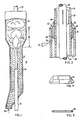
- a fluidized bed reactor 10 including a vessel 12.
- the vessel 12 is generally cyclindrical including a lower body 14, an enlarged upper body 16, an inlet feed system 18, an ash outlet 20 at the bottom, and a product gas outlet 22 at the top.
- FIG 1 also depicts the combustion jet penetration depth 26 shown as extending from the top of the feed system 18 to an area in which slugging operational characteristics may occur as a result of enlarged bubble formation which can attain the dimension of the inner diameter of the vessel. It is desirable to enhance penetration depth, the overall penetration jet volume, and the time period during which the particulate matter exists within and immediately about the combustion jet in order to ensure complete combustion of the char. It has been found that this condition is enhanced when the annular velocity is between one and two times the minimum fluidization velocity, Umf, of the solids in the annulus and the jet velocity is 18 m./sec. or greater.
- Umf minimum fluidization velocity
- Figures 2 and 3 show additional details of the feed system 18. It is arranged so as to provide a combined coaxial feed, and a combined coaxial and radial discharge of fluid mediums, particularly providing coaxial vertical upward feed for char or coal particles in a transport gas.
- the primary structures include three tubular members, an inner tube 28, an intermediate tube 30, and an outer tube 32, respectively surrounding one another radially so as to form an inner annulus 34 and an outer annulus 36.
- the tubes are preferably concentric.
- the inner tube 28 is a 1-inch schedule 40 pipe of Incoloy 800.
- Char fines or coals in a transport gas which can comprise recycled product gas, steam, air, nitrogen and carbon dioxide, enter . the inner tube through nozzle 40 and are injected in the reactor vessel 12 through the open top of the inner tube 28 at a temperature in the range of 138°C.
- the spacer plates 38 provide for an even distribution at the upper end of the inner annulus. The solid feeds are thus discharged upwardly directly into the combustion jet.
- the intermediate tube 30 is a 63 mm schedule 40S pipe of type 316 stainless steel.
- An oxidant such as air or oxygen, enters the inner annulus 34 through an inlet nozzle 42, and also flows upwardly into the combustion jet through the open upper end of the annulus 34.
- a cooling and fluidization booster medium such as steam or air enters the outer annulus 36 through inlet nozzle 44 and flows upwardly, coaxially with the solids feed and oxidant.
- the top of the outer annulus 36 is sealed by structure including a truncated conical transition member 46, shown in Figure 4.
- the transition member of type 304 stainless steel, is affixed to the top of the 10 cm schedule 80S outer tube by weld 48.
- the inside diameter of the upper end of the transition member is 73 mm, so as to form a slip fit with respect to the intermediate tube 30.
- the slip fit allows for differential thermal expansion among the components without generation of undue stresses.
- the outer side of the transition member is shaped to provide a steep slope, the angle a being preferably greater than 50°. This ensures that particulate matter does not stagnate on the outer surface.
- seal ring 50 Affixed to and surrounding the radial periphery of the intermediate tube 30 is a seal ring 50.
- the seal ring is comprised of type 316 stainless steel having an outside diameter of 95 mm.
- packing material 52 such as a temperature resistant refractory fibre blanket, which forms a pressure seal so that the cooling and booster fluidization medium cannot escape through the gap 54 resulting from the slip fit.
- the outer tube 32 is provided with perforations 56 through which the steam or recycle gas is radially discharged into the reactor.
- the perforations 56 are downwardly sloped, preferably at an angle, /3, of approximately 30° with respect to the horizontal. In this manner the steam or recycle gas, injected into the outer annulus at approximately 230°C, provides not only cooling of the intermediate tube, but also booster fluidization to particulate matter in the lower body 14.
- the con- flguration further provides the ability to inject particulate coal, without pretreatment, through the inner tube, alternative to, or in combination With, injection of char. Since the particulate coal is surrounded by an oxidant as it enters the high energy jet region, the outer surface of the coal particles is rapidly oxidized, preventing agglomeration, thus eliminating the need for a separate decaking pretreatment of the coal.
- the downward injection of the steam prevents formation of an enlarged fixed bed in the lower body 14, boosting fluidization and upward stripping flow of char into the high energy zone while allowing downward motion and eventual withdrawal of ash through the outlet 20.
- the coaxial feed system provides separate flow rate control of each of the three input mediums, allowing adjustment to the optimum conditions for each reactor.
Landscapes
- Chemical & Material Sciences (AREA)
- Engineering & Computer Science (AREA)
- Combustion & Propulsion (AREA)
- Oil, Petroleum & Natural Gas (AREA)
- Organic Chemistry (AREA)
- Fluidized-Bed Combustion And Resonant Combustion (AREA)
- Devices And Processes Conducted In The Presence Of Fluids And Solid Particles (AREA)
- Crucibles And Fluidized-Bed Furnaces (AREA)
Claims (6)
Applications Claiming Priority (2)
| Application Number | Priority Date | Filing Date | Title |
|---|---|---|---|
| US06/058,237 US4282010A (en) | 1979-07-17 | 1979-07-17 | Fluidized bed injection assembly for coal gasification |
| US58237 | 1987-06-04 |
Publications (2)
| Publication Number | Publication Date |
|---|---|
| EP0022897A1 EP0022897A1 (de) | 1981-01-28 |
| EP0022897B1 true EP0022897B1 (de) | 1983-11-30 |
Family
ID=22015539
Family Applications (1)
| Application Number | Title | Priority Date | Filing Date |
|---|---|---|---|
| EP80100786A Expired EP0022897B1 (de) | 1979-07-17 | 1980-02-15 | Wirbelschichtbett-Einspritzvorrichtung für Kohlevergasung |
Country Status (8)
| Country | Link |
|---|---|
| US (1) | US4282010A (de) |
| EP (1) | EP0022897B1 (de) |
| JP (1) | JPS55125197A (de) |
| AU (1) | AU534846B2 (de) |
| CA (1) | CA1125514A (de) |
| DE (1) | DE3065742D1 (de) |
| IN (1) | IN151538B (de) |
| ZA (1) | ZA80484B (de) |
Families Citing this family (15)
| Publication number | Priority date | Publication date | Assignee | Title |
|---|---|---|---|---|
| US4312638A (en) * | 1980-04-18 | 1982-01-26 | Westinghouse Electric Corp. | Coal gasification process |
| US4391611A (en) * | 1981-03-05 | 1983-07-05 | The United States Of America As Represented By The United States Department Of Energy | Gasification system |
| US4493636A (en) * | 1981-03-05 | 1985-01-15 | The United States Of America As Represented By The United States Department Of Energy | Gasification system |
| IN155792B (de) * | 1981-06-09 | 1985-03-09 | Krw Energy Systems Inc | |
| DE3136645A1 (de) * | 1981-09-16 | 1983-03-24 | Bergwerksverband Gmbh, 4300 Essen | Verfahren zur dosierung von, insbesondere backenden,brennstoffen in einen wirbelschichtreaktor sowie verfahren zum betreiben einer solchen vorrichtung |
| US4469487A (en) * | 1982-09-20 | 1984-09-04 | Bergwerksverband Gmbh | Arrangement for and method of dosing fuel in fluidized bed reactor |
| JPS6015491A (ja) * | 1983-07-08 | 1985-01-26 | Mitsubishi Heavy Ind Ltd | 石炭ガス化装置及び石炭ガス化方法 |
| ZA85155B (en) * | 1984-01-13 | 1985-10-30 | Krw Energy Systems Inc | Adjustable booster for fluidized bed gasifiers |
| US4569681A (en) * | 1984-03-12 | 1986-02-11 | Krw Energy Systems Inc. | Fluidization and solids recirculation process for a fluidized bed gasifier |
| US5772708A (en) * | 1995-03-17 | 1998-06-30 | Foster Wheeler Development Corp. | Coaxial coal water paste feed system for gasification reactor |
| US6719952B1 (en) * | 2000-02-21 | 2004-04-13 | Westinghouse Electric Company Llc | Fluidized bed reaction design |
| US6737556B2 (en) * | 2002-10-21 | 2004-05-18 | Exxonmobil Chemical Patents Inc. | Method and system for reducing decomposition byproducts in a methanol to olefin reactor system |
| WO2008042078A1 (en) * | 2006-10-03 | 2008-04-10 | Univation Technologies, Llc | Effervescent nozzle for catalyst injection |
| US8850826B2 (en) * | 2009-11-20 | 2014-10-07 | Egt Enterprises, Inc. | Carbon capture with power generation |
| CN103087778B (zh) * | 2013-01-28 | 2014-11-05 | 新奥科技发展有限公司 | 一种射流管、带有该射流管的流化床反应器及煤催化气化方法 |
Citations (1)
| Publication number | Priority date | Publication date | Assignee | Title |
|---|---|---|---|---|
| EP0021461A1 (de) * | 1979-06-13 | 1981-01-07 | Shell Internationale Researchmaatschappij B.V. | Verfahren und Brenner zum Vergasen festen Brennstoffs |
Family Cites Families (15)
| Publication number | Priority date | Publication date | Assignee | Title |
|---|---|---|---|---|
| US2886421A (en) * | 1947-06-02 | 1959-05-12 | Kellogg M W Co | Treatment of carbon-containing materials |
| US2898204A (en) * | 1953-12-24 | 1959-08-04 | Koppers Co Inc | Process for production of combustible gases |
| FR1262818A (fr) * | 1960-06-18 | 1961-06-05 | Steinmueller Gmbh L & C | Procédé et dispositif pour réaliser l'oxydation d'un combustible pulvérisé |
| US3110578A (en) * | 1961-08-16 | 1963-11-12 | State University And The Schoo | Gasification process for the production of synthesis gases |
| US3708887A (en) * | 1970-09-08 | 1973-01-09 | Fmc Corp | Nozzles for fluidized bed vessel construction plate |
| BE793881A (fr) * | 1972-01-11 | 1973-07-11 | Westinghouse Electric Corp | Appareil pour la desulfurisation et la gazeification complete du charbon |
| US3861862A (en) * | 1972-09-05 | 1975-01-21 | Andrew B Steever | Fuel gun for fluidized bed reactor |
| US3847563A (en) * | 1973-05-02 | 1974-11-12 | Westinghouse Electric Corp | Multi-stage fluidized bed coal gasification apparatus and process |
| US3933445A (en) * | 1973-10-15 | 1976-01-20 | Exxon Research And Engineering Company | Process and apparatus for preventing deposits on a gas inlet nozzle |
| DE2533010A1 (de) * | 1974-07-26 | 1976-02-05 | Commw Scient Ind Res Org | Reaktor mit einem spoutbett oder spoutbett-fluidatbett |
| US4200494A (en) * | 1974-12-27 | 1980-04-29 | Union Carbide Corporation | Method of preventing defluidization of carbonaceous particles |
| ZA757406B (en) * | 1974-12-27 | 1976-11-24 | Union Carbide Corp | Method of avoiding agglomeration in fluidized bed processes |
| NL7514128A (nl) * | 1975-12-04 | 1977-06-07 | Shell Int Research | Werkwijze en inrichting voor de partiele verbran- ding van koolpoeder. |
| AT349432B (de) * | 1976-12-30 | 1979-04-10 | Waagner Biro Ag | Gasverteiler in schuettgutbehandlungs- einrichtungen |
| US4173189A (en) * | 1977-01-21 | 1979-11-06 | Combustion Engineering, Inc. | Boiler cold start using pulverized coal in ignitor burners |
-
1979
- 1979-07-17 US US06/058,237 patent/US4282010A/en not_active Expired - Lifetime
-
1980
- 1980-01-25 CA CA344,374A patent/CA1125514A/en not_active Expired
- 1980-01-28 ZA ZA00800484A patent/ZA80484B/xx unknown
- 1980-02-02 IN IN126/CAL/80A patent/IN151538B/en unknown
- 1980-02-15 DE DE8080100786T patent/DE3065742D1/de not_active Expired
- 1980-02-15 EP EP80100786A patent/EP0022897B1/de not_active Expired
- 1980-02-19 AU AU55717/80A patent/AU534846B2/en not_active Ceased
- 1980-03-17 JP JP3280480A patent/JPS55125197A/ja active Pending
Patent Citations (1)
| Publication number | Priority date | Publication date | Assignee | Title |
|---|---|---|---|---|
| EP0021461A1 (de) * | 1979-06-13 | 1981-01-07 | Shell Internationale Researchmaatschappij B.V. | Verfahren und Brenner zum Vergasen festen Brennstoffs |
Also Published As
| Publication number | Publication date |
|---|---|
| AU5571780A (en) | 1981-01-22 |
| IN151538B (de) | 1983-05-14 |
| ZA80484B (en) | 1981-04-29 |
| US4282010A (en) | 1981-08-04 |
| EP0022897A1 (de) | 1981-01-28 |
| AU534846B2 (en) | 1984-02-16 |
| DE3065742D1 (en) | 1984-01-05 |
| JPS55125197A (en) | 1980-09-26 |
| CA1125514A (en) | 1982-06-15 |
Similar Documents
| Publication | Publication Date | Title |
|---|---|---|
| EP0022897B1 (de) | Wirbelschichtbett-Einspritzvorrichtung für Kohlevergasung | |
| EP1348011B1 (de) | Multifacetten-vergaser und verwandte verfahren | |
| US3981690A (en) | Agglomerating combustor-gasifier method and apparatus for coal gasification | |
| US4858538A (en) | Partial combustion burner | |
| US4887962A (en) | Partial combustion burner with spiral-flow cooled face | |
| US4865542A (en) | Partial combustion burner with spiral-flow cooled face | |
| AU754147B2 (en) | Method and device for producing combustible gas, synthesis gas and reducing gas from solid fuels | |
| CA1308306C (en) | Partial combustion burner with spiral-flow cooled face | |
| US3018174A (en) | High pressure pulverized coal gasifier | |
| JPS6027716B2 (ja) | 固体燃料からガスを製造する方法および装置 | |
| US5782032A (en) | Coal gasification furnace with a slag tap hole of specific shape | |
| US5620487A (en) | High performance, multi-stage, pressurized, airblown, entrained flow coal gasifier system | |
| CN201010630Y (zh) | 流化床粉煤气化反应器 | |
| AU2003294753B2 (en) | Method and plant for producing low-temperature coke | |
| US3864100A (en) | Method and apparatus for gasification of pulverized coal | |
| EP0021461B2 (de) | Verfahren und Brenner zum Vergasen festen Brennstoffs | |
| US5772708A (en) | Coaxial coal water paste feed system for gasification reactor | |
| US4647294A (en) | Partial oxidation apparatus | |
| AU749262B2 (en) | Method for producing liquid pig iron | |
| CN105733686B (zh) | 环式撞击型气化炉 | |
| EP0130630B1 (de) | Brenner und Verfahren zur Vergasung von festem Brennstoff | |
| US4519321A (en) | Burner for the partial combustion of solid fuel | |
| EP0108425B1 (de) | Brenner für die unvollständige Verbrennung von feinverteiltem Festbrennstoff | |
| WO1994016038A1 (en) | Circular slag tap for a gasifier | |
| JPH083361B2 (ja) | 微粉原料ガス化用バーナ及び微粉原料ガス化装置 |
Legal Events
| Date | Code | Title | Description |
|---|---|---|---|
| PUAI | Public reference made under article 153(3) epc to a published international application that has entered the european phase |
Free format text: ORIGINAL CODE: 0009012 |
|
| AK | Designated contracting states |
Designated state(s): BE DE FR GB |
|
| 17P | Request for examination filed |
Effective date: 19810725 |
|
| GRAA | (expected) grant |
Free format text: ORIGINAL CODE: 0009210 |
|
| AK | Designated contracting states |
Designated state(s): BE DE FR GB |
|
| PGFP | Annual fee paid to national office [announced via postgrant information from national office to epo] |
Ref country code: DE Payment date: 19831130 Year of fee payment: 5 |
|
| PGFP | Annual fee paid to national office [announced via postgrant information from national office to epo] |
Ref country code: FR Payment date: 19831220 Year of fee payment: 5 |
|
| PGFP | Annual fee paid to national office [announced via postgrant information from national office to epo] |
Ref country code: BE Payment date: 19831231 Year of fee payment: 5 |
|
| REF | Corresponds to: |
Ref document number: 3065742 Country of ref document: DE Date of ref document: 19840105 |
|
| ET | Fr: translation filed | ||
| PLBE | No opposition filed within time limit |
Free format text: ORIGINAL CODE: 0009261 |
|
| STAA | Information on the status of an ep patent application or granted ep patent |
Free format text: STATUS: NO OPPOSITION FILED WITHIN TIME LIMIT |
|
| 26N | No opposition filed | ||
| REG | Reference to a national code |
Ref country code: GB Ref legal event code: 732 |
|
| REG | Reference to a national code |
Ref country code: FR Ref legal event code: TP |
|
| PG25 | Lapsed in a contracting state [announced via postgrant information from national office to epo] |
Ref country code: BE Effective date: 19860228 |
|
| BERE | Be: lapsed |
Owner name: KRW ENERGY SYSTEMS INC. Effective date: 19860228 |
|
| GBPC | Gb: european patent ceased through non-payment of renewal fee | ||
| PG25 | Lapsed in a contracting state [announced via postgrant information from national office to epo] |
Ref country code: FR Free format text: LAPSE BECAUSE OF NON-PAYMENT OF DUE FEES Effective date: 19871030 |
|
| PG25 | Lapsed in a contracting state [announced via postgrant information from national office to epo] |
Ref country code: DE Effective date: 19871103 |
|
| REG | Reference to a national code |
Ref country code: FR Ref legal event code: ST |
|
| PG25 | Lapsed in a contracting state [announced via postgrant information from national office to epo] |
Ref country code: GB Effective date: 19881118 |
|
| ITCP | It: supplementary protection certificate |
Spc suppl protection certif: CCP 448 |