EP0022435B1 - Evacuation system for particulate waste material - Google Patents
Evacuation system for particulate waste material Download PDFInfo
- Publication number
- EP0022435B1 EP0022435B1 EP80850108A EP80850108A EP0022435B1 EP 0022435 B1 EP0022435 B1 EP 0022435B1 EP 80850108 A EP80850108 A EP 80850108A EP 80850108 A EP80850108 A EP 80850108A EP 0022435 B1 EP0022435 B1 EP 0022435B1
- Authority
- EP
- European Patent Office
- Prior art keywords
- container
- waste material
- branch conduits
- air
- collecting
- Prior art date
- Legal status (The legal status is an assumption and is not a legal conclusion. Google has not performed a legal analysis and makes no representation as to the accuracy of the status listed.)
- Expired
Links
- 239000002699 waste material Substances 0.000 title claims abstract description 27
- 238000000151 deposition Methods 0.000 claims description 4
- 239000000463 material Substances 0.000 claims description 3
- 239000011236 particulate material Substances 0.000 claims 1
- 239000000428 dust Substances 0.000 description 4
- 230000004075 alteration Effects 0.000 description 1
- 238000010586 diagram Methods 0.000 description 1
- 238000007599 discharging Methods 0.000 description 1
- 238000005265 energy consumption Methods 0.000 description 1
- 239000012530 fluid Substances 0.000 description 1
- 238000000034 method Methods 0.000 description 1
Images


Classifications
-
- B—PERFORMING OPERATIONS; TRANSPORTING
- B23—MACHINE TOOLS; METAL-WORKING NOT OTHERWISE PROVIDED FOR
- B23Q—DETAILS, COMPONENTS, OR ACCESSORIES FOR MACHINE TOOLS, e.g. ARRANGEMENTS FOR COPYING OR CONTROLLING; MACHINE TOOLS IN GENERAL CHARACTERISED BY THE CONSTRUCTION OF PARTICULAR DETAILS OR COMPONENTS; COMBINATIONS OR ASSOCIATIONS OF METAL-WORKING MACHINES, NOT DIRECTED TO A PARTICULAR RESULT
- B23Q11/00—Accessories fitted to machine tools for keeping tools or parts of the machine in good working condition or for cooling work; Safety devices specially combined with or arranged in, or specially adapted for use in connection with, machine tools
- B23Q11/0042—Devices for removing chips
- B23Q11/0046—Devices for removing chips by sucking
-
- B—PERFORMING OPERATIONS; TRANSPORTING
- B65—CONVEYING; PACKING; STORING; HANDLING THIN OR FILAMENTARY MATERIAL
- B65F—GATHERING OR REMOVAL OF DOMESTIC OR LIKE REFUSE
- B65F5/00—Gathering or removal of refuse otherwise than by receptacles or vehicles
- B65F5/005—Gathering or removal of refuse otherwise than by receptacles or vehicles by pneumatic means, e.g. by suction
-
- B—PERFORMING OPERATIONS; TRANSPORTING
- B65—CONVEYING; PACKING; STORING; HANDLING THIN OR FILAMENTARY MATERIAL
- B65G—TRANSPORT OR STORAGE DEVICES, e.g. CONVEYORS FOR LOADING OR TIPPING, SHOP CONVEYOR SYSTEMS OR PNEUMATIC TUBE CONVEYORS
- B65G53/00—Conveying materials in bulk through troughs, pipes or tubes by floating the materials or by flow of gas, liquid or foam
- B65G53/04—Conveying materials in bulk pneumatically through pipes or tubes; Air slides
- B65G53/24—Gas suction systems
Definitions
- This invention relates to an evacuation system for transporting particulate waste material from a plurality of suction points to a central collecting point. It is particularly but not exclusively applicable to the removal of the dust produced by machines such as woodworking machines in a factory.
- Certain previously known systems for transporting waste material such as sanding dust or sawdust, have comprised branch conduits leading from the various machines which produce the dust to a common duct or manifold. These systems have incorporated a suction blower to produce an air flow from the machines through the branch conduits and the manifold to a central collecting point and have relied on this air flow to transport the dust over the full distance from the machine to the collecting point. This prevents the waste material from being spread openly in the air and results in substantial improvements in the working environment.
- GB-A-722 992 relates to a pneumatic conveyor plant in which two or more independently operated ducts are connected to a separating device for discharging the material carried by the conveying air.
- each duct is provided with throttling members controlled in such a way that the sum of the airflow resistances in the conveyor ducts remain substantially constant.
- the object of the present invention is to provide a much simpler solution with higher efficiency and reliability.
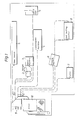
- the factory shown in Fig. 1 comprises a number of different woodworking machines, e.g. a saw bench 1, an upright drill 2, a dowel machine 3, a combination machine 4, a band saw 5, a planing machine 6, a cutter 7 and a belt buffing machine 8, from which the waste material is sucked away in branch conduits to the central collecting point which comprises a container 9. From the container the transport air is further brought to flow through an air filter 10.
- the transport air in the system is generated in a conventional manner by means of one or several blowers (not shown).
- the upper portion of the container 9 is provided with several openings 11 for the branch conduits 12 which are connected to the container, whereas the lower portion is provided with a funnel-shaped bottom 13 to collect the waste material which is conveyed through an emptying duct 14 to a depositing container 15 which preferably should be transportable.
- the dimensions of the collecting container 9 relative to the branch conduits are thus chosen that the air velocity in the container 9 is insufficient to carry the waste material through an exhaust air channel 19A which is arranged in the upper part of the container 9 and which is connected to a filter chamber 10.
- the lower portion of the filter chamber is in a conventional way formed with a funnel-shaped bottom 16 with a duct 17 for emptying the waste material into a container 18.
- the filter chamber is connected to suction blowers via a channel 19B, said blowers generating the necessary under-pressure in the system for producing the air flow which carries the waste material.
- the filter in the filter chamber 10 can be of any conventional kind, for example in the form of a cyclone or a hose filter. Even combinations of these two kinds can be utilized.
- Fig. 3 the collecting container 9 is schematically shown in a side-cross-sectional view and it is shown how the valves 20 can be arranged to close the openings 11 for the branch conduits 12.
- the valves 20 are operated by means of pressure air cylinders 21 and the valve axes 22 are provided with pistons 23 which are displaced in cylinders depending on which one of the two pressure air valves 24 and 24' are operated to permit pressure air to be entered into the cylinder 21.
- valves can of course be located in the branch conduits at any suitable point between the suction point and the collecting container and be designed as conventional throttle valves or sliding valves.
- the waste material which is extracted and collected in the funnel 13 can be transported to a container in a separate pneumatic system.
- Fig. 4 it is schematically shown how the under-pressure in the collecting container 9 is maintained at a constant level by means of a bypass valve 25, the position of which is controlled by means of a pressure sensing device 26 which is arranged in a servo-circuit and which generates pulses to a device 27 controlling the position of the valve.
- This valve is connected to a duct 28 through which air is sucked away from the inside of a building. This has the advantage that a substantially constant air flow is sucked away from the interior of the building and that the air speed between the container 9 and the filter 10 also will remain at a constant value.
- the prerequisite is of course that the under- pressure in the collecting container 9 is maintained at a constant level and this is provided by means of the servo-system described above.
- the suction duct 28 could suitably be provided with a noise trap 29.
- the under-pressure in the system is generated by means of a blower 30 schematically indicated in the figure.
- the purified air could suitably be used as return air or could be exhausted to the open air through a heat exchanger.
- the transportation of waste material from each machine will only be in operation when the machine is operating.
- the machine controls the pressure air controlled valves shown in Fig. 3 by means of a switch or a photoelectric cell on the machine table, which will be affected when the machine is taken into operation.
Landscapes
- Engineering & Computer Science (AREA)
- Mechanical Engineering (AREA)
- Refuse Collection And Transfer (AREA)
- Air Transport Of Granular Materials (AREA)
- Catching Or Destruction (AREA)
- Air Bags (AREA)
- Fertilizers (AREA)
- Housing For Livestock And Birds (AREA)
- Prevention Of Fouling (AREA)
- Disintegrating Or Milling (AREA)
- Crucibles And Fluidized-Bed Furnaces (AREA)
- Glass Compositions (AREA)
Abstract
Description
- This invention relates to an evacuation system for transporting particulate waste material from a plurality of suction points to a central collecting point. It is particularly but not exclusively applicable to the removal of the dust produced by machines such as woodworking machines in a factory.
- Certain previously known systems for transporting waste material such as sanding dust or sawdust, have comprised branch conduits leading from the various machines which produce the dust to a common duct or manifold. These systems have incorporated a suction blower to produce an air flow from the machines through the branch conduits and the manifold to a central collecting point and have relied on this air flow to transport the dust over the full distance from the machine to the collecting point. This prevents the waste material from being spread openly in the air and results in substantial improvements in the working environment.
- There are, however, several drawbacks with these previously known systems. Since the waste material is conveyed all the way from the suction points to the central collecting point first through relatively thin branch conduits and then through a comparatively coarse manifold the magnitude of the air velocities within all parts of the system must be thus adapted that the air is capable of carrying the waste material even through the coarse manifold. Thus, in a system which relies on the air flow in the manifold to carry the waste material, any substantial alteration in the number of points from which waste material is to be removed requires virtually a rebuilding of the system, because the changed airflow in the manifold will require a different cross-sectional area if the correct flow velocity is to be maintained. The plant must consequently from the beginning be adapted and dimensioned to the maximum number of machines which are to be connected to the system and which can be simultaneously operated. This means that these previously known systems do not permit any flexibility but can only be utilized for a certain number of machines located at certain points which have been calculated from the beginning.
- A further drawback is of course that both the fan capacity and the filter capacity will have to be adapted to the most unfavourable operating conditions to provide safe transportation of waste material from suction points within all parts of the plant to the central collecting point. This means that both the transport fans and the filters have to be heavily overdimensioned, which in turn will cause a comparatively large energy consumption.
- Alternatively, it has been suggested to transport the waste material from different suction points to a common manifold in which the material is extracted and removed by means of a conveyor to a central collecting point. The conveyor can either be a mechanical conveyor, a blower or even a transport fluid. This conveying system will eliminate a number of drawbacks in previously known systems, which have been indicated above, but in certain cases, for example in small industries, a system in accordance with this known arrangement is unnecessary, big and expensive.
- GB-A-722 992 relates to a pneumatic conveyor plant in which two or more independently operated ducts are connected to a separating device for discharging the material carried by the conveying air. In this plant each duct is provided with throttling members controlled in such a way that the sum of the airflow resistances in the conveyor ducts remain substantially constant.
- A disadvantage of this known plant is of course that in a system with a great number of branch ducts there will be a need for the same number of throttling members and control gauges which makes the system complicated, vulnerable and expensive.
- The object of the present invention is to provide a much simpler solution with higher efficiency and reliability.
- This object is realized by the fact that means are provided to detect the under-pressure in the collecting container to control either the speed of the transport blower, or valve means in a separate suction conduit which does not transport waste material, in order to maintain the under-pressure in the container at substantially constant value and hence the air speed in the branch conduits which are open for communication.
- One embodiment of the invention will now be described in more detail with reference to the accompanying drawings, in which
- Fig. 1 is a diagrammatic planview of a workshop in which the different machines are connected to an evacuation system according to the invention,
- Fig. 2 is a sideview of a container forming part of the system according to Fig. 1,
- Fig. 3 is a sectional view through the container shown in Figs. 1 and 2, and
- Fig. 4 is a principal block diagram of a system according to the invention.
- The factory shown in Fig. 1 comprises a number of different woodworking machines, e.g. a
saw bench 1, anupright drill 2, adowel machine 3, a combination machine 4, a band saw 5, a planing machine 6, a cutter 7 and abelt buffing machine 8, from which the waste material is sucked away in branch conduits to the central collecting point which comprises acontainer 9. From the container the transport air is further brought to flow through anair filter 10. The transport air in the system is generated in a conventional manner by means of one or several blowers (not shown). - As appears in Fig. 2 the upper portion of the
container 9 is provided withseveral openings 11 for thebranch conduits 12 which are connected to the container, whereas the lower portion is provided with a funnel-shaped bottom 13 to collect the waste material which is conveyed through anemptying duct 14 to a depositingcontainer 15 which preferably should be transportable. The dimensions of thecollecting container 9 relative to the branch conduits are thus chosen that the air velocity in thecontainer 9 is insufficient to carry the waste material through anexhaust air channel 19A which is arranged in the upper part of thecontainer 9 and which is connected to afilter chamber 10. The lower portion of the filter chamber is in a conventional way formed with a funnel-shaped bottom 16 with aduct 17 for emptying the waste material into acontainer 18. The filter chamber is connected to suction blowers via a channel 19B, said blowers generating the necessary under-pressure in the system for producing the air flow which carries the waste material. The filter in thefilter chamber 10 can be of any conventional kind, for example in the form of a cyclone or a hose filter. Even combinations of these two kinds can be utilized. - In Fig. 3 the
collecting container 9 is schematically shown in a side-cross-sectional view and it is shown how thevalves 20 can be arranged to close theopenings 11 for thebranch conduits 12. In the embodiment shown in this Figure thevalves 20 are operated by means ofpressure air cylinders 21 and thevalve axes 22 are provided withpistons 23 which are displaced in cylinders depending on which one of the twopressure air valves 24 and 24' are operated to permit pressure air to be entered into thecylinder 21. - The valves can of course be located in the branch conduits at any suitable point between the suction point and the collecting container and be designed as conventional throttle valves or sliding valves.
- Instead of the method of collecting the waste material by means of a depositing
container 15 located under the collectingcontainer 9 as shown in Fig. 2, the waste material which is extracted and collected in thefunnel 13 can be transported to a container in a separate pneumatic system. - In Fig. 4 it is schematically shown how the under-pressure in the collecting
container 9 is maintained at a constant level by means of abypass valve 25, the position of which is controlled by means of apressure sensing device 26 which is arranged in a servo-circuit and which generates pulses to adevice 27 controlling the position of the valve. This valve is connected to aduct 28 through which air is sucked away from the inside of a building. This has the advantage that a substantially constant air flow is sucked away from the interior of the building and that the air speed between thecontainer 9 and thefilter 10 also will remain at a constant value. - The prerequisite is of course that the under- pressure in the collecting
container 9 is maintained at a constant level and this is provided by means of the servo-system described above. Thesuction duct 28 could suitably be provided with anoise trap 29. The under-pressure in the system is generated by means of ablower 30 schematically indicated in the figure. The purified air could suitably be used as return air or could be exhausted to the open air through a heat exchanger. - The transportation of waste material from each machine will only be in operation when the machine is operating. The machine controls the pressure air controlled valves shown in Fig. 3 by means of a switch or a photoelectric cell on the machine table, which will be affected when the machine is taken into operation.
Claims (1)
- An evacuation system for conveying particulate waste material from a plurality of collecting places to a common and centrally located depositing place, in which the material by means of transport air is continuously transferred in branch conduits (12) from the collecting places to the common depositing place, comprising a collecting container (9), the upper portion of which being provided with several openings (11) for the branch conduits (12) which are connected to the container (9) and the lower portion of which being provided with means for disposing of the particulate material, a transport air blower (30) being connected to the collecting container (9) to generate the airflow in the branch conduits necessary for the transportation of the waste material, individually operated valves (20) being arranged in each of the branch conduits (12) to open or close each branch conduit for air communication, the dimensions of the branch conduits and the collecting container (9) being thus chosen that the velocity of airflow in each branch conduit is sufficiently high but in the container is insufficiently high to carry the particulate waste material, characterized in that means (26) are provided to detect the underpressure in the collecting container (9) to control either the speed of the transport blower (30), or valve means (26) in a separate suction conduit (28) which does not transport waste material, in order to maintain the under- pressure in the container (9) at substantially constant value and hence the air speed in the branch conduits which are open for communication.
Priority Applications (1)
| Application Number | Priority Date | Filing Date | Title |
|---|---|---|---|
| AT80850108T ATE15998T1 (en) | 1979-07-06 | 1980-07-01 | SUCTION SYSTEM FOR DUSTY WASTE. |
Applications Claiming Priority (2)
| Application Number | Priority Date | Filing Date | Title |
|---|---|---|---|
| SE7905920A SE445909B (en) | 1979-07-06 | 1979-07-06 | PLANT FOR SUGAR TRANSPORT OF WASTE MATERIAL FROM A MULTIPLE LOCAL COLLECTION PLACES TO A COMMON WASTE DISPOSAL |
| SE7905920 | 1979-07-06 |
Publications (2)
| Publication Number | Publication Date |
|---|---|
| EP0022435A1 EP0022435A1 (en) | 1981-01-14 |
| EP0022435B1 true EP0022435B1 (en) | 1985-10-09 |
Family
ID=20338464
Family Applications (1)
| Application Number | Title | Priority Date | Filing Date |
|---|---|---|---|
| EP80850108A Expired EP0022435B1 (en) | 1979-07-06 | 1980-07-01 | Evacuation system for particulate waste material |
Country Status (6)
| Country | Link |
|---|---|
| EP (1) | EP0022435B1 (en) |
| JP (1) | JPS5612228A (en) |
| AT (1) | ATE15998T1 (en) |
| DE (1) | DE3071164D1 (en) |
| NO (1) | NO153762C (en) |
| SE (1) | SE445909B (en) |
Families Citing this family (12)
| Publication number | Priority date | Publication date | Assignee | Title |
|---|---|---|---|---|
| JPS61193786A (en) * | 1985-02-22 | 1986-08-28 | N S K Warner Kk | Joining method for metallic member |
| FR2625484B1 (en) * | 1987-12-30 | 1990-06-08 | Kergadallan Pierre | PNEUMATIC TRANSPORTATION INSTALLATION, IN PARTICULAR FOR SUCTION DISCHARGE OF WASTE PRODUCED BY A PLURALITY OF MACHINES, SUCH AS WOOD MACHINES |
| DE4021953C2 (en) * | 1990-07-10 | 1994-05-26 | Kaltenbach & Voigt | Device for processing dental technology products |
| US5160292A (en) * | 1991-01-30 | 1992-11-03 | Parker Kenneth W | Vacuum system for multiple work areas |
| DE4406539C2 (en) * | 1994-02-28 | 1996-08-14 | Siemens Ag | Method and device for operating a central exhaust system, in particular for woodworking companies, with which a minimum value of the total volume flow in the exhaust air collecting pipe is maintained |
| DE10012182C1 (en) * | 2000-03-13 | 2001-08-09 | Karl Schaffer | Surface treatment device for contaminated floor surface has differential pressure switch monitoring suction system for extraction of removed material for safety shut-down |
| ES2245535B9 (en) * | 2002-12-05 | 2011-11-18 | Ros Roca, S.A. | SYSTEM FOR COLLECTION OF URBAN WASTE. |
| SE531005C2 (en) * | 2007-03-08 | 2008-11-18 | Envac Ab | Method and system for energy recovery in vacuum-driven waste collection systems |
| ES2301454B1 (en) * | 2008-02-20 | 2009-03-16 | Envac Iberia, S.A. | METHOD FOR RECOVERY AND REUSE OF ENERGY FROM A SYSTEM OF COLLECTION OF WASTE BY SUCTION AND SYSTEM TO CARRY OUT THAT METHOD. |
| CN103817131B (en) * | 2014-03-03 | 2015-11-25 | 柏美迪康环保科技(上海)有限公司 | Multifunctional dust collection device |
| DE102014007402A1 (en) * | 2014-05-20 | 2015-11-26 | Festool Gmbh | Hand machine tool with a particle removal port |
| EP3438158B1 (en) | 2017-08-01 | 2020-11-25 | Evonik Operations GmbH | Production of sioc-linked siloxanes |
Family Cites Families (14)
| Publication number | Priority date | Publication date | Assignee | Title |
|---|---|---|---|---|
| US1448430A (en) * | 1922-09-07 | 1923-03-13 | Earle W Brown | Dust catcher |
| US1816223A (en) * | 1927-11-28 | 1931-07-28 | Kirk & Blum Mfg Company | Automatic cut-off |
| GB722992A (en) * | 1948-10-01 | 1955-02-02 | Miag Vertriebs Gmbh | Improvements in or relating to pneumatic conveyor plant |
| DE838676C (en) * | 1949-06-21 | 1952-05-12 | Waagner Biro Ag | Filter system for gases |
| US3120432A (en) * | 1960-08-01 | 1964-02-04 | Hammond Machinery Builders Inc | Dust collector and support for the bag thereof |
| US3236565A (en) * | 1963-12-31 | 1966-02-22 | Phillips Petroleum Co | Dustless pneumatic conveyor and process |
| US3314098A (en) * | 1964-09-14 | 1967-04-18 | Kirk & Blum Mfg Co | Dust collecting plenum installation |
| GB1300821A (en) * | 1970-01-30 | 1972-12-20 | Ingenieurbureau Dr Brehm A G | Improvements relating to the compacting of particulate material |
| AT317517B (en) * | 1972-07-31 | 1974-09-10 | Dieter Klingler | Extraction system for a large number of metal-cutting machines, especially woodworking machines |
| JPS49118186A (en) * | 1973-03-19 | 1974-11-12 | ||
| NL7414152A (en) * | 1973-12-08 | 1975-06-10 | Zimmermann Azo Maschf | IMPROVEMENT OF A WEIGHING DEVICE FOR A PNEUMATIC TRANSPORT INSTALLATION. |
| JPS5338302U (en) * | 1976-09-07 | 1978-04-04 | ||
| IT1110853B (en) * | 1977-12-19 | 1986-01-06 | Johns Manville | CONVEYING AND COLLECTION SYSTEM OF SPECIAL MATERIALS FOR EXAMPLE INDUSTRIAL PROCESSING WASTE |
| SE412050C (en) * | 1978-06-26 | 1986-09-15 | Flaekt Ab | PLANT FOR SUGAR TRANSPORT OF WASTE MATERIAL |
-
1979
- 1979-07-06 SE SE7905920A patent/SE445909B/en not_active IP Right Cessation
-
1980
- 1980-07-01 AT AT80850108T patent/ATE15998T1/en not_active IP Right Cessation
- 1980-07-01 NO NO801979A patent/NO153762C/en unknown
- 1980-07-01 DE DE8080850108T patent/DE3071164D1/en not_active Expired
- 1980-07-01 EP EP80850108A patent/EP0022435B1/en not_active Expired
- 1980-07-03 JP JP9120280A patent/JPS5612228A/en active Pending
Also Published As
| Publication number | Publication date |
|---|---|
| SE7905920L (en) | 1981-02-27 |
| JPS5612228A (en) | 1981-02-06 |
| ATE15998T1 (en) | 1985-10-15 |
| DE3071164D1 (en) | 1985-11-14 |
| NO153762B (en) | 1986-02-10 |
| SE445909B (en) | 1986-07-28 |
| NO801979L (en) | 1981-01-07 |
| NO153762C (en) | 1986-05-21 |
| EP0022435A1 (en) | 1981-01-14 |
Similar Documents
| Publication | Publication Date | Title |
|---|---|---|
| US4457043A (en) | Sweeper particularly for collecting dust-like material, and the utilization thereof | |
| US4201256A (en) | Sawdust collector | |
| EP0022435A1 (en) | Evacuation system for particulate waste material | |
| US4490162A (en) | Low pressure HEPA filtration system for particulate matter | |
| GB1568643A (en) | Process for the cleaning of grain and a cleaning machine for carrying out the said process | |
| US5217509A (en) | Filtration system | |
| GB2078131A (en) | Apparatus for removing airborne particles | |
| CN206527114U (en) | A kind of integral type electrostatic cleaner | |
| CA2083055A1 (en) | System for separation of materials using suction air power | |
| US6905528B2 (en) | Conveying air filtration system | |
| CN1067277A (en) | Ragging picker of improved textile industry | |
| SU1727914A1 (en) | Garbage sorting-out and reloading station | |
| US5205847A (en) | Air cleaning apparatus | |
| GB2173389A (en) | Suction system for cigarette machines | |
| US4960350A (en) | Process of stalling the speeds of articles to be conveyed in a pneumatic conveying system and a device therefor | |
| EP1075353A1 (en) | System for separation of debris from shot blast media | |
| US3635003A (en) | Centrifugal dust collector for the waste gases of a sinter machine for ores, building materials and the like | |
| US3849091A (en) | Closed loop air filtration system | |
| US3178862A (en) | Apparatus for sucking-off and collecting dust | |
| US3311420A (en) | Vacuum cleaning apparatus for particulate materials | |
| US1801255A (en) | Dust-collecting system for coal-handling plants | |
| CN113019022A (en) | Dust recovery system and control method thereof | |
| SU504644A1 (en) | Pneumatic waste disposal system | |
| SU1745371A1 (en) | Pneumatic separator | |
| JPH0721259Y2 (en) | Feather sorter |
Legal Events
| Date | Code | Title | Description |
|---|---|---|---|
| PUAI | Public reference made under article 153(3) epc to a published international application that has entered the european phase |
Free format text: ORIGINAL CODE: 0009012 |
|
| AK | Designated contracting states |
Designated state(s): AT BE CH DE FR GB IT NL |
|
| 17P | Request for examination filed |
Effective date: 19810217 |
|
| ITF | It: translation for a ep patent filed | ||
| RAP1 | Party data changed (applicant data changed or rights of an application transferred) |
Owner name: FLAEKT AKTIEBOLAG |
|
| GRAA | (expected) grant |
Free format text: ORIGINAL CODE: 0009210 |
|
| AK | Designated contracting states |
Designated state(s): AT BE CH DE FR GB IT LI NL |
|
| REF | Corresponds to: |
Ref document number: 15998 Country of ref document: AT Date of ref document: 19851015 Kind code of ref document: T |
|
| REF | Corresponds to: |
Ref document number: 3071164 Country of ref document: DE Date of ref document: 19851114 |
|
| ET | Fr: translation filed | ||
| PGFP | Annual fee paid to national office [announced via postgrant information from national office to epo] |
Ref country code: AT Payment date: 19860710 Year of fee payment: 7 |
|
| PLBE | No opposition filed within time limit |
Free format text: ORIGINAL CODE: 0009261 |
|
| STAA | Information on the status of an ep patent application or granted ep patent |
Free format text: STATUS: NO OPPOSITION FILED WITHIN TIME LIMIT |
|
| 26N | No opposition filed | ||
| PGFP | Annual fee paid to national office [announced via postgrant information from national office to epo] |
Ref country code: NL Payment date: 19870731 Year of fee payment: 8 |
|
| PG25 | Lapsed in a contracting state [announced via postgrant information from national office to epo] |
Ref country code: AT Effective date: 19880701 |
|
| PG25 | Lapsed in a contracting state [announced via postgrant information from national office to epo] |
Ref country code: LI Effective date: 19880731 Ref country code: CH Effective date: 19880731 |
|
| PG25 | Lapsed in a contracting state [announced via postgrant information from national office to epo] |
Ref country code: NL Effective date: 19890201 |
|
| NLV4 | Nl: lapsed or anulled due to non-payment of the annual fee | ||
| REG | Reference to a national code |
Ref country code: CH Ref legal event code: PL |
|
| PGFP | Annual fee paid to national office [announced via postgrant information from national office to epo] |
Ref country code: GB Payment date: 19940621 Year of fee payment: 15 |
|
| PGFP | Annual fee paid to national office [announced via postgrant information from national office to epo] |
Ref country code: DE Payment date: 19940622 Year of fee payment: 15 |
|
| PGFP | Annual fee paid to national office [announced via postgrant information from national office to epo] |
Ref country code: FR Payment date: 19940711 Year of fee payment: 15 |
|
| PGFP | Annual fee paid to national office [announced via postgrant information from national office to epo] |
Ref country code: BE Payment date: 19940808 Year of fee payment: 15 |
|
| PG25 | Lapsed in a contracting state [announced via postgrant information from national office to epo] |
Ref country code: GB Effective date: 19950701 |
|
| PG25 | Lapsed in a contracting state [announced via postgrant information from national office to epo] |
Ref country code: BE Effective date: 19950731 |
|
| BERE | Be: lapsed |
Owner name: FLAKT A.B. Effective date: 19950731 |
|
| GBPC | Gb: european patent ceased through non-payment of renewal fee |
Effective date: 19950701 |
|
| PG25 | Lapsed in a contracting state [announced via postgrant information from national office to epo] |
Ref country code: DE Effective date: 19960402 |
|
| PG25 | Lapsed in a contracting state [announced via postgrant information from national office to epo] |
Ref country code: FR Effective date: 19960430 |
|
| REG | Reference to a national code |
Ref country code: FR Ref legal event code: ST |
|
| REG | Reference to a national code |
Ref country code: FR Ref legal event code: ST |
|
| REG | Reference to a national code |
Ref country code: FR Ref legal event code: ST |