EP0022378B1 - Luggage case handle assembly - Google Patents
Luggage case handle assembly Download PDFInfo
- Publication number
- EP0022378B1 EP0022378B1 EP80302354A EP80302354A EP0022378B1 EP 0022378 B1 EP0022378 B1 EP 0022378B1 EP 80302354 A EP80302354 A EP 80302354A EP 80302354 A EP80302354 A EP 80302354A EP 0022378 B1 EP0022378 B1 EP 0022378B1
- Authority
- EP
- European Patent Office
- Prior art keywords
- openings
- cover
- luggage case
- gripping member
- handle assembly
- Prior art date
- Legal status (The legal status is an assumption and is not a legal conclusion. Google has not performed a legal analysis and makes no representation as to the accuracy of the status listed.)
- Expired
Links
- 239000002184 metal Substances 0.000 claims description 10
- 239000000463 material Substances 0.000 claims description 7
- 239000004033 plastic Substances 0.000 description 3
- 229920003023 plastic Polymers 0.000 description 3
- 238000010276 construction Methods 0.000 description 2
- 230000000284 resting effect Effects 0.000 description 2
- 239000004676 acrylonitrile butadiene styrene Substances 0.000 description 1
- 238000000034 method Methods 0.000 description 1
Images

Classifications
-
- A—HUMAN NECESSITIES
- A45—HAND OR TRAVELLING ARTICLES
- A45C—PURSES; LUGGAGE; HAND CARRIED BAGS
- A45C13/00—Details; Accessories
- A45C13/26—Special adaptations of handles
-
- Y—GENERAL TAGGING OF NEW TECHNOLOGICAL DEVELOPMENTS; GENERAL TAGGING OF CROSS-SECTIONAL TECHNOLOGIES SPANNING OVER SEVERAL SECTIONS OF THE IPC; TECHNICAL SUBJECTS COVERED BY FORMER USPC CROSS-REFERENCE ART COLLECTIONS [XRACs] AND DIGESTS
- Y10—TECHNICAL SUBJECTS COVERED BY FORMER USPC
- Y10S—TECHNICAL SUBJECTS COVERED BY FORMER USPC CROSS-REFERENCE ART COLLECTIONS [XRACs] AND DIGESTS
- Y10S16/00—Miscellaneous hardware, e.g. bushing, carpet fastener, caster, door closer, panel hanger, attachable or adjunct handle, hinge, window sash balance
- Y10S16/902—Unitary handle composed of different cooperating materials
Definitions
- the present invention relates generally to a handle assembly, and, more particulariy, to an improved luggage case, handle assembly.
- U.S. Patent Specification No. 3430742 describes a luggage case handle assembly comprising an elongate gripping member having a pair of mutually-spaced longitudinally-extending grooves in its surface and first and second longitudinally-directed openings in respective opposite ends.
- a one piece metal cover has longitudinal edges received in the grooves in the gripping member.
- First and second stanchions for securing the handle to the luggage case each have a stub shaft which is received in a respective one of first and second openings in the cover.
- the gripping member is formed of relatively hard plastics material. It is the aim of the present invention to provide a handle which is more comfortable to hold and, to this end, the gripping member is formed of a soft compliant material. In the above-mentioned specification the gripping member is secured to the cover by clinching or press fitting. These techniques are not suitable for maintaining a soft compliant gripping member in place because the compliant material will easily roll or work out of any such retaining cover.
- the present invention overcomes these problems by providing a gripping member which is of soft compliant material, by providing first and second end members having parts received in the first and second openings in the gripping member and parts extending in the same plane at an obtuse angle to the longitudinal axis of the gripping member and in that the metal cover overlies the first and second end members and in that means are provided for securing the metal cover to the first and second end members.
- a luggage case of the variety frequently referred to as a train case is identified generally as at 10, and includes a lower container shell 11 releasably joined to a cover 12 by latches 13, for example.
- the handle assembly 14 to be described is secured to the top lid of the cover 12 and is seen to have a generally trapezoidal appearance with the handle gripping portion being straight- line and parallel to the luggage case cover, and with two end portions extending angularly downwardly from the gripping portion of rotative securement to the cover.
- the handle assembly 14 is seen to include in its various components and elongated gripping member 15, first and second end parts 16 and 17 for sliding receipt within the ends of the gripping portion, and a half-shell frame 18 received about the gripping member and two end parts unitarily securing them together.
- First and second stanchions 19 and 20 are affixed to the cover 12 of the case and each includes a stub shaft 21 which are received through openings 38 in the frame 18 for rotatably mounting the handle assembly to the cover 12.
- the member 15 is of a total length slightly greater than that necessary to enable grasping with the four fingers of one hand. It is substantially rectangular in cross-section with the lower corners rounded off making them more comfortable to the grip.
- a pair of grooves 22 and 23 extend longitudinally along the upper surface of the member and lying closely adjacent the outer sides thereof. The central portion of the member between the grooves extends above the grooves and outer edge portions of the member.
- An opening 24 extends completely throughout the body of the gripping member 15 and in cross section is generally trapezoidal with the narrow width toward the bottom.
- the bottom wall surface of the member 15 is a straight line, as can be seen best in Figure 3 whereas the top wall surface is formed immediately adjacent each end to taper downwardly a slight extent for a purpose to be described.
- the gripping member is molded from flexible rubber or pliant synthetic plastic material since this will add to the comfort of the user by being soft and pliable to the grip.
- the handle end part includes an elongate, U-shaped channel 25 which is integrally joined with a body member 26. More particularly, the channel 25 is of cross-sectional dimensions and geometry generally the same as only slightly smaller than those of the opening 24 in the gripping member 15, thereby enabling the channel member to be fittingly received within that opening as shown in Figure 3.
- the body member 26 extends angularly away from channel 25 (e.g., 45-90 degrees) and what is the outwardly directed surface in assembly has a pair of extended shoulders 27 and 28 formed along the body side walls, which shoulders have a mutual spacing substantially identical to that of the grooves 22 and 23.
- An upstanding mounting post 30 has a threaded opening 31 therein for a purpose to be described.
- the lowermost end of 26 is faced off at substantially 90 degrees to the channel 25 and includes a recessed shoulder 32.
- the members 16 and 17 are of molded one-piece construction. Any one of a number of hard plastics materials, such as acrylonitrile-butadiene-styrene (ABS) are suitable for this purpose. Alternatively, they may be made of metal.
- ABS acrylonitrile-butadiene-styrene
- the frame 18 consists of a thin metal sheet stamped into a shape including a rectangular center strip extending throughout its complete length with two side or edge walls 33 and 34. From the side, the frame is seen to have a straight line central portion 35 and two end portions 36 and 37 formed to 35 and lying in the same plane. Each outer end of the frame end portions is faced off at 90 degrees to the central portion and includes an opening therein to be more particularly described.
- the shape and dimensions of the frame are such that the central portion side walls 33 and 34 can be received into the grooves 22 and 23 of the gripping member with the central portion of the frame in full intimate contact with the intervening parts of the gripping member (Figure 6). Also, these frame edge walls in the frame end portions are so dimensioned as to permit receipt on 16 and 17 with the edges resting on shoulders 27 and 28.
- the opening 38 in each end of the frame 18 is oblong or egg-shaped with the narrow width being at the top and the broader width at the bottom. This shape is keyed as will be described to permit a locking engagement with parts on the stanchions 19 and 20.
- the stanchions 19 and 20 are identical, therefore only 19 will be described in detail, and is seen to include in its major aspect a generally triangular body.
- a cylindrical post 39 extends out from one surface thereof for passing through an opening provided in the top of the case cover 12 and via which the stanchion is secured by suitable threaded member. Slightly spaced from the post 39 is a cylindrical positioning pin 40 for extending through a further opening in the cover to orient the stanchion in a fixed predetermined manner.
- the U-shaped channel member 25 of each end part 16, 17 is pressed into an end opening 24 of the gripping member 15.
- the half-shell frame 18 is then placed onto the gripping member and end parts with the frame edge walls 33 and 34 disposed within grooves 22 and 23 and resting on shoulders 27 and 28. Also, the terminal end portions of the frame are fitted into the recessed shoulders 32 of the gripping member end portions.
- a rivet 44 or optionally a threaded member, extends through an opening 31 in the frame for securement in the post 30.
- the oblong head 21 of each stanchion is aligned and passed through a respective frame opening 38 and rotated to the locking position shown in Figure 5.
- the post 39 is secured to the luggage cover top by threaded means 43 with the positioning key 40 also properly located within a receiving opening on the cover.
Landscapes
- Purses, Travelling Bags, Baskets, Or Suitcases (AREA)
- Details Of Rigid Or Semi-Rigid Containers (AREA)
Description
- The present invention relates generally to a handle assembly, and, more particulariy, to an improved luggage case, handle assembly.
- U.S. Patent Specification No. 3430742 describes a luggage case handle assembly comprising an elongate gripping member having a pair of mutually-spaced longitudinally-extending grooves in its surface and first and second longitudinally-directed openings in respective opposite ends. A one piece metal cover has longitudinal edges received in the grooves in the gripping member. First and second stanchions for securing the handle to the luggage case, each have a stub shaft which is received in a respective one of first and second openings in the cover.
- In the U.S. Patent Specification No. 3430742 the gripping member is formed of relatively hard plastics material. It is the aim of the present invention to provide a handle which is more comfortable to hold and, to this end, the gripping member is formed of a soft compliant material. In the above-mentioned specification the gripping member is secured to the cover by clinching or press fitting. These techniques are not suitable for maintaining a soft compliant gripping member in place because the compliant material will easily roll or work out of any such retaining cover.
- The present invention overcomes these problems by providing a gripping member which is of soft compliant material, by providing first and second end members having parts received in the first and second openings in the gripping member and parts extending in the same plane at an obtuse angle to the longitudinal axis of the gripping member and in that the metal cover overlies the first and second end members and in that means are provided for securing the metal cover to the first and second end members.
- An embodiment of the invention will now be described by way of example with reference to the accompanying drawings of which:-
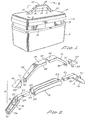
- Figure 1 is a perspective view of a luggage case showing a handle assembly according to the invention mounted thereon;
- Figure 2 is an exploded view of the various parts of the handle assembly of Figure 1;
- Figure 3 is an enlarged fragmentary section taken along the line 3-3 of Figure 1;
- Figure 4 is an enlarged fragmentary section of the mounting stanchion of the handle assembly of Figure 1 shown interconnected with the handle parts;
- Figure 5 is a sectional end view taken along the line 5-5 of Figure 4;
- Figure 6 is a sectional end view along the line 6-6 of Figure 3; and
- Figure 7 is a sectional partially schematic view showing the handle assembly arranged at 90° to that shown in Figure 5.
- With reference now to Figure 1, a luggage case of the variety frequently referred to as a train case, is identified generally as at 10, and includes a lower container shell 11 releasably joined to a
cover 12 bylatches 13, for example. Thehandle assembly 14 to be described is secured to the top lid of thecover 12 and is seen to have a generally trapezoidal appearance with the handle gripping portion being straight- line and parallel to the luggage case cover, and with two end portions extending angularly downwardly from the gripping portion of rotative securement to the cover. - Turning now to Figure 2, the
handle assembly 14 is seen to include in its various components andelongated gripping member 15, first andsecond end parts shell frame 18 received about the gripping member and two end parts unitarily securing them together. First andsecond stanchions cover 12 of the case and each includes astub shaft 21 which are received throughopenings 38 in theframe 18 for rotatably mounting the handle assembly to thecover 12. - For the ensuing description of the gripping
member 15 reference is made simultaneously to Figures 2 and 6. Themember 15 is of a total length slightly greater than that necessary to enable grasping with the four fingers of one hand. It is substantially rectangular in cross-section with the lower corners rounded off making them more comfortable to the grip. A pair ofgrooves opening 24 extends completely throughout the body of thegripping member 15 and in cross section is generally trapezoidal with the narrow width toward the bottom. The bottom wall surface of themember 15 is a straight line, as can be seen best in Figure 3 whereas the top wall surface is formed immediately adjacent each end to taper downwardly a slight extent for a purpose to be described. The gripping member is molded from flexible rubber or pliant synthetic plastic material since this will add to the comfort of the user by being soft and pliable to the grip. - Since the
end parts member 16 will be described in detail. The handle end part includes an elongate, U-shapedchannel 25 which is integrally joined with abody member 26. More particularly, thechannel 25 is of cross-sectional dimensions and geometry generally the same as only slightly smaller than those of the opening 24 in thegripping member 15, thereby enabling the channel member to be fittingly received within that opening as shown in Figure 3. - Preferably, the
body member 26 extends angularly away from channel 25 (e.g., 45-90 degrees) and what is the outwardly directed surface in assembly has a pair of extendedshoulders grooves upstanding mounting post 30 has a threadedopening 31 therein for a purpose to be described. The lowermost end of 26 is faced off at substantially 90 degrees to thechannel 25 and includes arecessed shoulder 32. - Preferably, the
members - The
frame 18 consists of a thin metal sheet stamped into a shape including a rectangular center strip extending throughout its complete length with two side oredge walls central portion 35 and twoend portions portion side walls grooves shoulders - As can be seen best in Figures 5 and 7, the opening 38 in each end of the
frame 18 is oblong or egg-shaped with the narrow width being at the top and the broader width at the bottom. This shape is keyed as will be described to permit a locking engagement with parts on thestanchions - The
stanchions cylindrical post 39 extends out from one surface thereof for passing through an opening provided in the top of thecase cover 12 and via which the stanchion is secured by suitable threaded member. Slightly spaced from thepost 39 is acylindrical positioning pin 40 for extending through a further opening in the cover to orient the stanchion in a fixed predetermined manner. On a flat surface at 90 degrees to that carrying thepost 39 andpin 40, there is astub shaft 21, the outer end of which is formed into anoblong head 42 of geometry identical to the opening 38 in the end ofmember 18. - In assembly, the U-shaped
channel member 25 of eachend part member 15. The half-shell frame 18 is then placed onto the gripping member and end parts with theframe edge walls grooves shoulders recessed shoulders 32 of the gripping member end portions. Arivet 44, or optionally a threaded member, extends through anopening 31 in the frame for securement in thepost 30. Next, theoblong head 21 of each stanchion is aligned and passed through a respective frame opening 38 and rotated to the locking position shown in Figure 5. Finally, thepost 39 is secured to the luggage cover top by threadedmeans 43 with thepositioning key 40 also properly located within a receiving opening on the cover.
Claims (5)
Applications Claiming Priority (2)
| Application Number | Priority Date | Filing Date | Title |
|---|---|---|---|
| US06/056,207 US4280247A (en) | 1979-07-10 | 1979-07-10 | Luggage case handle assembly |
| US56207 | 1979-07-10 |
Publications (2)
| Publication Number | Publication Date |
|---|---|
| EP0022378A1 EP0022378A1 (en) | 1981-01-14 |
| EP0022378B1 true EP0022378B1 (en) | 1983-05-25 |
Family
ID=22002894
Family Applications (1)
| Application Number | Title | Priority Date | Filing Date |
|---|---|---|---|
| EP80302354A Expired EP0022378B1 (en) | 1979-07-10 | 1980-07-10 | Luggage case handle assembly |
Country Status (13)
| Country | Link |
|---|---|
| US (1) | US4280247A (en) |
| EP (1) | EP0022378B1 (en) |
| JP (1) | JPS5615703A (en) |
| KR (1) | KR840001505B1 (en) |
| AU (1) | AU535444B2 (en) |
| BR (1) | BR8003867A (en) |
| CA (1) | CA1126218A (en) |
| DE (1) | DE3063486D1 (en) |
| DK (1) | DK295780A (en) |
| ES (1) | ES257696Y (en) |
| HK (1) | HK80184A (en) |
| MX (1) | MX150840A (en) |
| ZA (1) | ZA803500B (en) |
Families Citing this family (13)
| Publication number | Priority date | Publication date | Assignee | Title |
|---|---|---|---|---|
| US4261078A (en) * | 1980-01-21 | 1981-04-14 | Samsonite Corporation | Carrying handle |
| US4364150A (en) * | 1980-08-06 | 1982-12-21 | Kidde, Inc. (Presto Lock Company Division) | Handle for luggage and the like |
| JPH0781176B2 (en) * | 1985-08-19 | 1995-08-30 | 日立金属株式会社 | Method for producing Fe-Co alloy |
| US4922576A (en) * | 1989-02-23 | 1990-05-08 | White Consolidated Industries, Inc. | Handle for appliances |
| USD358972S (en) | 1992-10-22 | 1995-06-06 | The Libman Company | Attachment bracket for a pivotal tool handle |
| US5704507A (en) * | 1995-09-22 | 1998-01-06 | Owens-Brockway Plastic Products Inc. | Plastic container with integral flexible handle |
| US5771537A (en) * | 1997-03-25 | 1998-06-30 | Ho; Chin-Lien | Handle device adapted to be attached to two mounting holes |
| US6826804B2 (en) | 2002-08-30 | 2004-12-07 | Palliser Furniture Ltd. | Furniture handle |
| US7401385B2 (en) * | 2005-01-11 | 2008-07-22 | Tektronix, Inc. | Molded instrument handle and method of manufacturing |
| US7549192B2 (en) * | 2006-01-17 | 2009-06-23 | Coeur, Inc. | Handle and method of manufacture |
| US20080073367A1 (en) * | 2006-09-05 | 2008-03-27 | Chen-Chi Chuang | Container device with tightly engaged cover |
| US7712590B1 (en) * | 2007-12-26 | 2010-05-11 | Hando Industrial Co., Ltd. | Luggage grip having simplified construction |
| CN104724352A (en) * | 2014-12-30 | 2015-06-24 | 苏州安特实业有限公司 | Square packaging container |
Family Cites Families (15)
| Publication number | Priority date | Publication date | Assignee | Title |
|---|---|---|---|---|
| GB377963A (en) * | 1931-04-30 | 1932-08-02 | Charles William Cheney | Handles of the kind used on attache cases, trunks, bags and the like |
| US2254506A (en) * | 1940-09-27 | 1941-09-02 | Wheary Trunk Co | Handle |
| US2678707A (en) * | 1951-12-31 | 1954-05-18 | Finkelstein William | Luggage handle |
| US2684736A (en) * | 1952-12-12 | 1954-07-27 | Wagner E R Mfg Co | Handle-attaching device |
| US2765888A (en) * | 1954-05-28 | 1956-10-09 | Finkelstein William | Luggage handle |
| US2913080A (en) * | 1958-06-30 | 1959-11-17 | Bruce Molded Plastics Inc | Luggage handles |
| FR1352002A (en) * | 1962-04-26 | 1964-02-07 | Heinrich Sudhaus Sohne Fa | Handle for trunks or similar items |
| US3103268A (en) * | 1962-10-10 | 1963-09-10 | Long Mfg Company Inc | Handle fastening mounts for receptacle handles |
| US3289798A (en) * | 1964-10-14 | 1966-12-06 | Kidde Co Presto Lock Div | Handle assembly for luggage or the like |
| US3451590A (en) * | 1967-06-21 | 1969-06-24 | Eastman Kodak Co | Recessed handle assembly |
| US3430742A (en) * | 1967-08-11 | 1969-03-04 | Kidde Co Presto Lock Div | Handle assembly for luggage or the like |
| US3531822A (en) * | 1968-10-30 | 1970-10-06 | Philadelphia Handle Co | Flexible molded plastic handle with cushioning grip containing air pockets |
| US3657764A (en) * | 1970-09-25 | 1972-04-25 | Batesville Casket Co Inc | Stationary hinge for casket handles |
| US3692155A (en) * | 1970-10-22 | 1972-09-19 | Lark Luggage Corp | Handle assembly |
| JPS5139588B2 (en) * | 1973-08-13 | 1976-10-28 |
-
1979
- 1979-07-10 US US06/056,207 patent/US4280247A/en not_active Expired - Lifetime
-
1980
- 1980-06-10 AU AU59196/80A patent/AU535444B2/en not_active Ceased
- 1980-06-12 ZA ZA00803500A patent/ZA803500B/en unknown
- 1980-06-20 BR BR8003867A patent/BR8003867A/en unknown
- 1980-07-03 CA CA355,352A patent/CA1126218A/en not_active Expired
- 1980-07-04 KR KR1019800002645A patent/KR840001505B1/en not_active Expired
- 1980-07-07 MX MX183066A patent/MX150840A/en unknown
- 1980-07-08 JP JP9320180A patent/JPS5615703A/en active Granted
- 1980-07-09 ES ES1980257696U patent/ES257696Y/en not_active Expired
- 1980-07-09 DK DK295780A patent/DK295780A/en not_active Application Discontinuation
- 1980-07-10 EP EP80302354A patent/EP0022378B1/en not_active Expired
- 1980-07-10 DE DE8080302354T patent/DE3063486D1/en not_active Expired
-
1984
- 1984-10-25 HK HK801/84A patent/HK80184A/en unknown
Also Published As
| Publication number | Publication date |
|---|---|
| US4280247A (en) | 1981-07-28 |
| ES257696U (en) | 1981-11-16 |
| ES257696Y (en) | 1982-05-16 |
| KR830003196A (en) | 1983-06-18 |
| MX150840A (en) | 1984-07-30 |
| HK80184A (en) | 1984-11-02 |
| KR840001505B1 (en) | 1984-09-29 |
| JPS5615703A (en) | 1981-02-16 |
| CA1126218A (en) | 1982-06-22 |
| JPS6323761B2 (en) | 1988-05-18 |
| BR8003867A (en) | 1981-04-22 |
| AU5919680A (en) | 1981-01-15 |
| DK295780A (en) | 1981-01-11 |
| EP0022378A1 (en) | 1981-01-14 |
| DE3063486D1 (en) | 1983-07-07 |
| ZA803500B (en) | 1981-06-24 |
| AU535444B2 (en) | 1984-03-22 |
Similar Documents
| Publication | Publication Date | Title |
|---|---|---|
| EP0022378A1 (en) | Luggage case handle assembly | |
| EP0032845B1 (en) | Carrying handle | |
| US5903978A (en) | Razor handle and caddy | |
| US4682803A (en) | Fish tongs | |
| USD412810S (en) | Concave shaped cooking lid with ergonomic handle | |
| US6049948A (en) | Handle for carrying a bag | |
| US3944033A (en) | Bag handle | |
| US3321798A (en) | Handle for lunch boxes | |
| CA1227350A (en) | Hot dog holder | |
| JPS6388212U (en) | ||
| JPS6217549U (en) | ||
| JPH03114728U (en) | ||
| JPH01114878U (en) | ||
| JPS638244Y2 (en) | ||
| JPS61201851U (en) | ||
| JPS61122596U (en) | ||
| JPH0258603U (en) | ||
| JPH0226522U (en) | ||
| JPS6219992U (en) | ||
| JPS61191308U (en) | ||
| JPS62139940U (en) | ||
| JPS6276136U (en) | ||
| JPH0349042U (en) | ||
| JPS61160867U (en) | ||
| JPH02120374U (en) |
Legal Events
| Date | Code | Title | Description |
|---|---|---|---|
| PUAI | Public reference made under article 153(3) epc to a published international application that has entered the european phase |
Free format text: ORIGINAL CODE: 0009012 |
|
| AK | Designated contracting states |
Designated state(s): BE CH DE FR GB IT LU NL SE |
|
| 17P | Request for examination filed |
Effective date: 19810217 |
|
| ITF | It: translation for a ep patent filed | ||
| GRAA | (expected) grant |
Free format text: ORIGINAL CODE: 0009210 |
|
| AK | Designated contracting states |
Designated state(s): BE CH DE FR GB IT LI LU NL SE |
|
| PGFP | Annual fee paid to national office [announced via postgrant information from national office to epo] |
Ref country code: LU Payment date: 19830706 Year of fee payment: 4 |
|
| REF | Corresponds to: |
Ref document number: 3063486 Country of ref document: DE Date of ref document: 19830707 |
|
| ET | Fr: translation filed | ||
| PG25 | Lapsed in a contracting state [announced via postgrant information from national office to epo] |
Ref country code: LU Free format text: LAPSE BECAUSE OF NON-PAYMENT OF DUE FEES Effective date: 19830731 |
|
| PLBE | No opposition filed within time limit |
Free format text: ORIGINAL CODE: 0009261 |
|
| STAA | Information on the status of an ep patent application or granted ep patent |
Free format text: STATUS: NO OPPOSITION FILED WITHIN TIME LIMIT |
|
| 26N | No opposition filed | ||
| PGFP | Annual fee paid to national office [announced via postgrant information from national office to epo] |
Ref country code: SE Payment date: 19840630 Year of fee payment: 5 |
|
| PGFP | Annual fee paid to national office [announced via postgrant information from national office to epo] |
Ref country code: FR Payment date: 19840801 Year of fee payment: 5 |
|
| PGFP | Annual fee paid to national office [announced via postgrant information from national office to epo] |
Ref country code: DE Payment date: 19840830 Year of fee payment: 5 |
|
| PGFP | Annual fee paid to national office [announced via postgrant information from national office to epo] |
Ref country code: CH Payment date: 19840928 Year of fee payment: 5 |
|
| PGFP | Annual fee paid to national office [announced via postgrant information from national office to epo] |
Ref country code: BE Payment date: 19840930 Year of fee payment: 5 |
|
| PGFP | Annual fee paid to national office [announced via postgrant information from national office to epo] |
Ref country code: NL Payment date: 19860731 Year of fee payment: 7 |
|
| PG25 | Lapsed in a contracting state [announced via postgrant information from national office to epo] |
Ref country code: SE Effective date: 19870711 |
|
| PG25 | Lapsed in a contracting state [announced via postgrant information from national office to epo] |
Ref country code: LI Effective date: 19870731 Ref country code: CH Effective date: 19870731 |
|
| BERE | Be: lapsed |
Owner name: SAMSONITE CORP. Effective date: 19870731 |
|
| PG25 | Lapsed in a contracting state [announced via postgrant information from national office to epo] |
Ref country code: NL Effective date: 19880201 |
|
| NLV4 | Nl: lapsed or anulled due to non-payment of the annual fee | ||
| PG25 | Lapsed in a contracting state [announced via postgrant information from national office to epo] |
Ref country code: FR Free format text: LAPSE BECAUSE OF NON-PAYMENT OF DUE FEES Effective date: 19880331 |
|
| REG | Reference to a national code |
Ref country code: CH Ref legal event code: PL |
|
| PG25 | Lapsed in a contracting state [announced via postgrant information from national office to epo] |
Ref country code: DE Effective date: 19880401 |
|
| GBPC | Gb: european patent ceased through non-payment of renewal fee | ||
| REG | Reference to a national code |
Ref country code: FR Ref legal event code: ST |
|
| PG25 | Lapsed in a contracting state [announced via postgrant information from national office to epo] |
Ref country code: GB Free format text: LAPSE BECAUSE OF NON-PAYMENT OF DUE FEES Effective date: 19881118 |
|
| PG25 | Lapsed in a contracting state [announced via postgrant information from national office to epo] |
Ref country code: BE Effective date: 19890731 |
|
| EUG | Se: european patent has lapsed |
Ref document number: 80302354.8 Effective date: 19880831 |