EP0022332A1 - Industrial robots - Google Patents
Industrial robots Download PDFInfo
- Publication number
- EP0022332A1 EP0022332A1 EP80302143A EP80302143A EP0022332A1 EP 0022332 A1 EP0022332 A1 EP 0022332A1 EP 80302143 A EP80302143 A EP 80302143A EP 80302143 A EP80302143 A EP 80302143A EP 0022332 A1 EP0022332 A1 EP 0022332A1
- Authority
- EP
- European Patent Office
- Prior art keywords
- arm
- rotative
- industrial robot
- finger
- robot according
- Prior art date
- Legal status (The legal status is an assumption and is not a legal conclusion. Google has not performed a legal analysis and makes no representation as to the accuracy of the status listed.)
- Granted
Links
Images


Classifications
-
- B—PERFORMING OPERATIONS; TRANSPORTING
- B23—MACHINE TOOLS; METAL-WORKING NOT OTHERWISE PROVIDED FOR
- B23Q—DETAILS, COMPONENTS, OR ACCESSORIES FOR MACHINE TOOLS, e.g. ARRANGEMENTS FOR COPYING OR CONTROLLING; MACHINE TOOLS IN GENERAL CHARACTERISED BY THE CONSTRUCTION OF PARTICULAR DETAILS OR COMPONENTS; COMBINATIONS OR ASSOCIATIONS OF METAL-WORKING MACHINES, NOT DIRECTED TO A PARTICULAR RESULT
- B23Q7/00—Arrangements for handling work specially combined with or arranged in, or specially adapted for use in connection with, machine tools, e.g. for conveying, loading, positioning, discharging, sorting
- B23Q7/04—Arrangements for handling work specially combined with or arranged in, or specially adapted for use in connection with, machine tools, e.g. for conveying, loading, positioning, discharging, sorting by means of grippers
- B23Q7/046—Handling workpieces or tools
-
- B—PERFORMING OPERATIONS; TRANSPORTING
- B25—HAND TOOLS; PORTABLE POWER-DRIVEN TOOLS; MANIPULATORS
- B25J—MANIPULATORS; CHAMBERS PROVIDED WITH MANIPULATION DEVICES
- B25J9/00—Programme-controlled manipulators
-
- B—PERFORMING OPERATIONS; TRANSPORTING
- B25—HAND TOOLS; PORTABLE POWER-DRIVEN TOOLS; MANIPULATORS
- B25J—MANIPULATORS; CHAMBERS PROVIDED WITH MANIPULATION DEVICES
- B25J9/00—Programme-controlled manipulators
- B25J9/02—Programme-controlled manipulators characterised by movement of the arms, e.g. cartesian coordinate type
- B25J9/04—Programme-controlled manipulators characterised by movement of the arms, e.g. cartesian coordinate type by rotating at least one arm, excluding the head movement itself, e.g. cylindrical coordinate type or polar coordinate type
- B25J9/045—Polar coordinate type
Definitions
- This invention relates to industrial robots.
- Industrial robots are often employed in machine tool operation and are adapted to exchange tools and workpieces so that the machining operation can proceed in a fully automatic manner.
- Industrial robots employed in such automated operation must meet a number of important requirements: they should permit a task to be performed quickly; they should be installable even where space is limited; and they should possess freedom of movement along a straight line as required to mount and dismount a workpiece.
- Hitherto disclosed industrial robots used in the automation of machine tool operation have been designed on the basis of cylindrical and polar coordinate systems or the like.
- an elongated, rod-like arm having a manipulator attached at one end is rotated about a fixed position which serves as the center of rotation, and the arm is extended or retracted to vary the distance between the manipulator and the center of rotation.
- Such an arrangement results in a large distance between the handling position of a workpiece mounted in a machine tool, such as the position of a chuck in a lathe, and the center of rotation of the robot.
- the arm projects rearwardly of the center of rotation to a great extent.
- an industrial robot which comprises:
- An embodiment of the present invention can provide an industrial robot which is capable of performing all necessary operations, even with a limited degree of freedom, by providing perpendicularly intersecting rotative mechanisms and making effective utilization of linear motion.
- an embodiment of the present invention can provide an industrial robot which employs a servo mechanism in a drive mechanism for driving finger and arm mechanisms.
- an industrial robot is provided with first and second rotative mechanisms adapted to support an arm. That is, the rotative mechanisms are linked together.
- the second rotative mechanism which cooperates in supporting the arm intersects the arm at right angles. That is, the axis of rotational movement caused by the second rotative mechanism is at right angles to the direction of the linkage.
- the first rotative mechanism is perpendicularly disposed with respect to the second rotative mechanism and supports the second rotative mechanism such that the attitude thereof can be changed. That is the axes of rotational movements which can be caused by the first and second mechanisms respectively are perpendicular to one another.
- the arm or linkage provides a 90° bend so that the axis of rotational movement of the first rotative mechanism and the second rotative mechanism are at 90° to one another.
- the first rotative mechanism is aligned with the arm or linkage and the second rotative mechanism is at right angles to the arm or linkage.
- the end of the second rotative mechanism not connected to the arm may be provided with a finger mechanism.
- the finger mechanism may be connected to the second rotative mechanism by way of a second arm or linkage.
- a transversely movable member, for moving the finger mechanism at right angles to the longitudinal direction thereof, may be provided, for example by arranging it to move the second arm at right angles to its longitudinal axis.
- the industrial robot comprises a first rotative mechanism having a first arm or link and a second arm or link provided at opposite ends thereof.
- the first arm is fixedly secured of a base.
- a second rotative mechanism is coupled at one end thereof to the second arm or link of the first rotative mechanism and has a third arm or link secured to the other end thereof.
- the second rotative mechanism is arranged such that the longitudinal axis thereof (i.e. the axis of rotation caused by the second rotative mechanism) crosses the longitudinal axis of the first rotative mechanism (i.e. the axis of rotation caused by the first rotative mechanism) at right angles.
- a finger mechanism is mounted on the arm of the second rotative mechanism (i.e. is linked to-that mechanism).
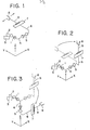
- Figs. 1 to 3 The basic structure of the arm mechanism belonging to a robot embodying the present invention is shown in Figs. 1 to 3, wherein Fig. 1 shows the arm mechanism at the beginning of an operational sequence, Fig. 2 during the course of the operational sequence, and Fig. 3 at the end of the operational sequence.
- a first rotative mechanism 1 is interposed between a pair of arms 2, 4 and is adapted to rotate the arm 4 relative to the arm 2 about the longitudinal axis of the first rotative mechanism 1 as seen in the Figures.
- the latter is secured at one end, as seen in the Figure, to a base 3 through the arm 2, which has a 90° bend, and is connected at the other end to the arm 4 which also has a 90° bend.
- a second rotative mechanism 5 is coupled at one end to the arm 4, and is connected at the other end to an arm 6.
- the arm 6 is configured to extend slightly from the second rotative mechanism 5 in the direction of the positive X-axis (as indicated in the Figure), then a short distance in the direction of the positive Z-axis (as indicated in the Figure), and finally over a major portion of its length in the direction of the positive Y-axis (as indicated in the Figure), this end of the arm being coupled to a transversally movable member 7.
- An arm 9 connects the transversally movable member 7 with a finger mechanism 8. It will be appreciated from Fig. 1 that the longitudinal axes of the respective rotative mechanism are arranged so as to cross each other at right angles.
- the robot arm mechanism described above is capable of being operated in the following manner.
- the transversally movable member 7 is actuated to move the finger mechanism 8 in directions along the X-axis (as indicated by arrows) from the position it is shown occupying in Fig. 1, with the arm 6 being held stationary.
- This causes the finger mechanism 8 to abut against and grip a machined workpiece held by, for example, a chuck in a machine tool.
- the member 7 is then reactuated to move the finger mechanism 8 back to the position it originally occupied in Fig. 1, whereby the finger mechanism extracts the workpiece from the chuck and continues to grip it firmly.
- the three degrees of freedom provided by the first rotative mechanism, the second rotative mechanism and the transversally movable member allow the finger mechanism 8 to be moved along two perpendicular side walls of a machine tool frame, and also permit the workpiece, after having been removed from the chuck, to be rotated by 90° and placed on the workpiece feeder without relying upon the twisting action of a wrist portion.
- the transversally movable member 7 can be actuated to raise the finger mechanism 8, after which the second rotative mechanism 5 is rotated to swing the finger mechanism 8.to a position above the - unmachined workpiece.
- the transversally movable member 7 is then reactuated so as to lower the finger mechanism 8 and permit it to grasp the unmachined workpiece.
- the latter is then fitted into the chuck by commanding the robot to reverse the foregoing sequence.
- FIG. 7 The external configuration of a robot in accordance with the second embodiment of the invention described above is shown in a perspective view in Fig. 7, in which reference numeral 11 denotes a machine tool, 12 a chuck provided on the machine tool, 13 a workpiece feeder, and 14 a workpiece. Like or corresponding component parts bear the same reference numerals as those used in Figs. 1 to 6.
- the robot shown in Fig. 7 operates as follows. First, the transversally movable member 7 is actuated to bring the finger mechanism 8 to the vicinity of the chuck 12 so that the finger mechanism can grasp a machined workpiece which is being held by the chuck. Following this the transversally movable member 7 is driven in the opposite direction to remove the workpiece from the chuck. Next the second rotative mechanism 5 is actuated to swing the finger mechanism 8 in a plane which is parallel to the Y-Z plane and move the finger mechanism to the position designated by numeral 8'.
- the first rotative mechanism 1 is actuated to swing the finger mechanism 8 in a plane which is parallel to the X-Z plane and move the finger member to the position designated by numeral 8", and the extendible shaft 10 is actuated to extend the arm 9.
- This operation positions the finger mechanism 8, which is still grasping the workpiece, over the workpiece feeder 13, so that the workpiece 14 can be set on the feeder by causing the finger mechanism 8 to release its grasp. Mounting an unmachined workpiece in the chuck of the machine tool can be carried out by the robot hand mechanism merely by reversing the foregoing sequence.
- the transversally movable member 7 includes a motor 15, a timing belt 16, a ball bearing feed screw 17, a bracket 18 and a ball bearing spline 19.
- the motor 15 is adapted to rotate the feed screw 17 through the timing belt 16.
- the bracket 18 for supporting the finger mechanism 8 is mounted on the ball bearing spline 19 and is fixed against rotational movement thereby.
- Fixedly secured to the bracket 18 is a nut 18a which is screwed onto the feed screw 17. To move the bracket 18 the motor 15 is driven to rotate the feed screw 17 via the timing belt 16.
- the nut 18a travels along the screw 17 as the latter rotates and causes-the bracket 18 to slide . along the ball bearing spline 19.
- the second rotative mechanism 5 includes a motor 20, a reduction gear 21, and a shaft 22 coupled to the reduction gear 21.
- Running the motor 20 rotatably drives the shaft 22 through the reduction gear 21 to swing the transversally movable member 7 which is connected to the shaft 22 through the arm 6.
- Fig. 8 While the robot embodied by the arrangement of Fig. 8 employs motors to drive the respective arms, it is also possible to substitute other actuators for the motors, such as air cylinders, hydraulic motors or hydraulic cylinders.
- a rotative mechanism can be considered to comprise a primary component, a secondary component and drive means operable to establish relative rotational movement between the primary and secondary components.
- the rotary shaft 27 for example, provides the primary component
- the motor 27 and associated means e.g. gear 24, belt 25
- the drive means and parts mounting the motor on the base 27-1 provide the secondary component.
- One end of the first rotative mechanism is provided in the coupling of the rotary shaft 27 to the bracket and this is the rotating end
- the other (stationary) end of the first rotative mechanism is provided in the mounting of the motor on the base 27-1.
- the ends of a rotative mechanism are parts thereof between which the mechanism can produce relative rotational movement and which are coupled or linked to other members not of the mechanism.
- an "arm" as shown schematically and symbolically in Figs. 1 to 6 can be identified with any effective mechanical coupling or link, for example, the bracket 26.
- the arm mechanism of a robot can be moved along the two perpendicular side walls of,a machine tool frame so that the space required for the robot to operate can be reduced markedly over the conventional robots that are based on polar or cylindrical coordinate systems.
- operation of the arm mechanism is quicker since smaller anglesare covered by the arms.
- the attitude of a workpiece is shifted by 90° at the same time that the workpiece is moved along the perpendicular side walls of the machine tool frame, it is no longer required that a wrist be twisted to align a horizontally disposed surface of the workpiece with the vertically disposed surface of the chuck prior to mounting of the workpiece.
- the hand can be furnished with an additional degree of freedom by providing the transversally movable member on the shaft connected to the finger mechanism, thereby facilitating such delicate operations as attaching and detaching a workpiece to and from the chuck. Still another degree of freedom is obtained by providing an arm with an extendible shaft to further enhance operation of the arm mechanism.
- the second rotative mechanism is linked to a movable gripping member
- the robot having a hand or manipulative member of the foregoing construction permits gripping member to be moved in a plane which is parallel to an X-Z plane, and then in a plane which is parallel to a Y-Z plane so that a workpiece or tool replacement can be moved along the perpendicular side walls of a machine tool frame.
- the end result is a quicker operating speed and a reduced floor space requirement for installation.
- the degrees of freedom can be increased by providing the robot arms or links with additional mechanisms, particularly between the second rotative mechanism and the gripping member, such as a rotative mechanism for rotating the gripping member about the arm or link, an extendible shaft for extending the arm or link, or a linear drive mechanism for moving the gripping member at right angles to the longitudinal axis of the arm or link.
- additional mechanisms particularly between the second rotative mechanism and the gripping member, such as a rotative mechanism for rotating the gripping member about the arm or link, an extendible shaft for extending the arm or link, or a linear drive mechanism for moving the gripping member at right angles to the longitudinal axis of the arm or link.
- - Servo mechanisms may constitute the means for driving the rotative mechanisms the extendible shaft and the linear drive mechanism.
Abstract
Description
- This invention relates to industrial robots.
- Industrial robots are often employed in machine tool operation and are adapted to exchange tools and workpieces so that the machining operation can proceed in a fully automatic manner. Industrial robots employed in such automated operation must meet a number of important requirements: they should permit a task to be performed quickly; they should be installable even where space is limited; and they should possess freedom of movement along a straight line as required to mount and dismount a workpiece.
- Hitherto disclosed industrial robots used in the automation of machine tool operation have been designed on the basis of cylindrical and polar coordinate systems or the like. In these industrial robots an elongated, rod-like arm having a manipulator attached at one end is rotated about a fixed position which serves as the center of rotation, and the arm is extended or retracted to vary the distance between the manipulator and the center of rotation. Such an arrangement results in a large distance between the handling position of a workpiece mounted in a machine tool, such as the position of a chuck in a lathe, and the center of rotation of the robot. In addition, the arm projects rearwardly of the center of rotation to a great extent. For these reasons the installed robot must be provid6d.with a large surrounding floor space so that the robot will not interfere with adjacent equipment-when going through its various motions. Much of this space is dead space. Moreover, since the arm is merely a single rod or shaft, a wide variety of manipulative operations is obviously impossible, and freedom of movement along a straight line for mounting and dismounting the workpiece, is lost. Thus it has not been possible to fully meet the requirements of an industrial robot as set forth above.
- According to the present invention there is provided an industrial robot which comprises:
- a first rotative mechanism;.
- an arm connected at one end thereof to the first rotative mechanism; and
- a second rotative mechanism connected at one end thereof to the other end of the arm;
- the first rotative mechanism being perpendicularly disposed with respect to the second rotative mechanism;
- so that the attitude of the second rotative mechanism can be changed by rotating the first rotative mechanism.
- According to the present invention there is also provided an industrial robot which comprises:
- a first rotative mechanism having a first arm and a second arm at respective opposite ends thereof, the first arm being fixedly secured to a base;
- a second rotative mechanism coupled at one end thereof to the second arm and having a third arm secured to the other end thereof, the second rotative mechanism being arranged such that the longitudinal axis thereof is at right angles to the longitudinal axis of said first rotative mechanism; and
- a finger mechanism mounted on the third arm.
- An embodiment of the present invention can provide an industrial robot which can be installed in close proximity to a machine tool and which is capable of minimizing working time.
- An embodiment of the present invention can provide an industrial robot which requires very little floor space for installation and which is capable of operating effectively even in a very limited amount of floor space.
- An embodiment of the present invention can provide an industrial robot which is capable of performing all necessary operations, even with a limited degree of freedom, by providing perpendicularly intersecting rotative mechanisms and making effective utilization of linear motion.
- Further, an embodiment of the present invention can provide an industrial robot which employs a servo mechanism in a drive mechanism for driving finger and arm mechanisms.
- Briefly, in one embodiment of the present invention, an industrial robot is provided with first and second rotative mechanisms adapted to support an arm. That is, the rotative mechanisms are linked together. The second rotative mechanism which cooperates in supporting the arm intersects the arm at right angles. That is, the axis of rotational movement caused by the second rotative mechanism is at right angles to the direction of the linkage. The first rotative mechanism is perpendicularly disposed with respect to the second rotative mechanism and supports the second rotative mechanism such that the attitude thereof can be changed. That is the axes of rotational movements which can be caused by the first and second mechanisms respectively are perpendicular to one another.
- For example, the arm or linkage provides a 90° bend so that the axis of rotational movement of the first rotative mechanism and the second rotative mechanism are at 90° to one another. In effect, it can be said, the first rotative mechanism is aligned with the arm or linkage and the second rotative mechanism is at right angles to the arm or linkage.
- The end of the second rotative mechanism not connected to the arm may be provided with a finger mechanism. The finger mechanism may be connected to the second rotative mechanism by way of a second arm or linkage.
- A transversely movable member, for moving the finger mechanism at right angles to the longitudinal direction thereof, may be provided, for example by arranging it to move the second arm at right angles to its longitudinal axis.
- In another embodiment of the present invention, the industrial robot comprises a first rotative mechanism having a first arm or link and a second arm or link provided at opposite ends thereof. The first arm is fixedly secured of a base. A second rotative mechanism is coupled at one end thereof to the second arm or link of the first rotative mechanism and has a third arm or link secured to the other end thereof. The second rotative mechanism is arranged such that the longitudinal axis thereof (i.e. the axis of rotation caused by the second rotative mechanism) crosses the longitudinal axis of the first rotative mechanism (i.e. the axis of rotation caused by the first rotative mechanism) at right angles. A finger mechanism is mounted on the arm of the second rotative mechanism (i.e. is linked to-that mechanism).
- Reference will be made, by way of example, to the accompanying drawings, in which:-
- Figs. 1 to 3 are- schematic perspective views for assistance in describing both the structure of and an operational sequence effected by an arm mechanism of a robot embodying the present invention;
- Fig. 4 is a schematic perspective view showing a different attitude of the arm mechanism of the robot;
- Figs. 5 and 6 are schematic perspective views useful in describing the structure and operation of another robot embodying the present invention;
- Fig. 7 is a perspective view illustrating the external appearance of a robot embodying the present invention; and
- Fig. 8 is a.perspective view showing the interior of the arm mechanism of a robot embodying the present invention.
- The basic structure of the arm mechanism belonging to a robot embodying the present invention is shown in Figs. 1 to 3, wherein Fig. 1 shows the arm mechanism at the beginning of an operational sequence, Fig. 2 during the course of the operational sequence, and Fig. 3 at the end of the operational sequence.
- A first rotative mechanism 1 is interposed between a pair of
arms arm 4 relative to thearm 2 about the longitudinal axis of the first rotative mechanism 1 as seen in the Figures. The latter is secured at one end, as seen in the Figure, to abase 3 through thearm 2, which has a 90° bend, and is connected at the other end to thearm 4 which also has a 90° bend. A secondrotative mechanism 5 is coupled at one end to thearm 4, and is connected at the other end to anarm 6. Thearm 6 is configured to extend slightly from the secondrotative mechanism 5 in the direction of the positive X-axis (as indicated in the Figure), then a short distance in the direction of the positive Z-axis (as indicated in the Figure), and finally over a major portion of its length in the direction of the positive Y-axis (as indicated in the Figure), this end of the arm being coupled to a transversallymovable member 7. Anarm 9 connects the transversallymovable member 7 with afinger mechanism 8. It will be appreciated from Fig. 1 that the longitudinal axes of the respective rotative mechanism are arranged so as to cross each other at right angles. - The robot arm mechanism described above is capable of being operated in the following manner. First, the transversally
movable member 7 is actuated to move thefinger mechanism 8 in directions along the X-axis (as indicated by arrows) from the position it is shown occupying in Fig. 1, with thearm 6 being held stationary. This causes thefinger mechanism 8 to abut against and grip a machined workpiece held by, for example, a chuck in a machine tool. Themember 7 is then reactuated to move thefinger mechanism 8 back to the position it originally occupied in Fig. 1, whereby the finger mechanism extracts the workpiece from the chuck and continues to grip it firmly. Next, the secondrotative mechanism 5 is driven to rotate thearm 9 by 90° in a plane parallel to the Y-Z plane, thereby placing thearm 9 in a vertical attitude, as shown in Fig. 2. The first rotative mechanism 1 is then rotated to turn thearm 9 in a plane parallel to the X-Z plane, as illustrated in Fig. 3, so that thefinger mechanism 8 is shifted at then stopped at a prescribed position above a workpiece feeder, by way of example. This is followed by actuation of the transversallymovable member 7 so as to lower thefinger mechanism 8, after which the finger mechanism is caused to loosen its grip and release the finished workpiece, thereby setting the workpiece on the feeder. - The three degrees of freedom provided by the first rotative mechanism, the second rotative mechanism and the transversally movable member allow the
finger mechanism 8 to be moved along two perpendicular side walls of a machine tool frame, and also permit the workpiece, after having been removed from the chuck, to be rotated by 90° and placed on the workpiece feeder without relying upon the twisting action of a wrist portion. - - The robot arm mechanism can also be operated by rotating the first rotative mechanism 1 prior to the second
rotative mechanism 5 to align the longitudinal axis of the secondrotative mechanism 5 with the Z-axis as shown in Fig. 4, after which the secondrotative mechanism 5 may be rotated to swing thefinger mechanism 8 in a horizontal plane, that is, in a plane which is parallel to the X-Y plane. Thus, if the secondrotative mechanism 5 is rotated starting from the attitude shown in Fig. 4, thefinger mechanism 8 can be moved along the surface of the workpiece feeder. If an unmachined workpiece is resting upon the workpiece feeder and is to be carried to the chuck, the transversallymovable member 7 can be actuated to raise thefinger mechanism 8, after which the secondrotative mechanism 5 is rotated to swing the finger mechanism 8.to a position above the - unmachined workpiece. The transversallymovable member 7 is then reactuated so as to lower thefinger mechanism 8 and permit it to grasp the unmachined workpiece. The latter is then fitted into the chuck by commanding the robot to reverse the foregoing sequence. - While the fundamental structure and operation of the robot arm mechanism in accordance with the present invention is as described above, a degree of freedom can be added by providing the arm mechanism with an extendible shaft. This will enable a greater variety of robot movements. Such a structure is shown in Figs. 5 and 6 which illustrate a second embodiment of the present invention. Here an
extendible shaft 10 is provided between thearm 9 and the transversallymovable member 7 to enable thefinger mechanism 8 to be moved longitudinally of thearm 9. - It should be noted that the variety of robot movements can be increased even further by providing the
arms arm 9 to permit the twisting of thefinger mechanism 8, and to provide a rotative mechanism that can swing thefinger mechanism 8 around the longitudinal axis of thearm 9. However, such wrist and rotative mechanisms are diverse in construction and well known in the art and need not be described in further detail. - The external configuration of a robot in accordance with the second embodiment of the invention described above is shown in a perspective view in Fig. 7, in which reference numeral 11 denotes a machine tool, 12 a chuck provided on the machine tool, 13 a workpiece feeder, and 14 a workpiece. Like or corresponding component parts bear the same reference numerals as those used in Figs. 1 to 6.
- The robot shown in Fig. 7 operates as follows. First, the transversally
movable member 7 is actuated to bring thefinger mechanism 8 to the vicinity of thechuck 12 so that the finger mechanism can grasp a machined workpiece which is being held by the chuck. Following this the transversallymovable member 7 is driven in the opposite direction to remove the workpiece from the chuck. Next the secondrotative mechanism 5 is actuated to swing thefinger mechanism 8 in a plane which is parallel to the Y-Z plane and move the finger mechanism to the position designated by numeral 8'. Thereafter the first rotative mechanism 1 is actuated to swing thefinger mechanism 8 in a plane which is parallel to the X-Z plane and move the finger member to the position designated bynumeral 8", and theextendible shaft 10 is actuated to extend thearm 9. This operation positions thefinger mechanism 8, which is still grasping the workpiece, over theworkpiece feeder 13, so that theworkpiece 14 can be set on the feeder by causing thefinger mechanism 8 to release its grasp. Mounting an unmachined workpiece in the chuck of the machine tool can be carried out by the robot hand mechanism merely by reversing the foregoing sequence. - One form of internal structure for a robot arm mechanism is shown in the perspective view of Fig. 8. The transversally
movable member 7 includes amotor 15, atiming belt 16, a ballbearing feed screw 17, abracket 18 and aball bearing spline 19. Themotor 15 is adapted to rotate thefeed screw 17 through thetiming belt 16. Thebracket 18 for supporting thefinger mechanism 8 is mounted on theball bearing spline 19 and is fixed against rotational movement thereby. Fixedly secured to thebracket 18 is a nut 18a which is screwed onto thefeed screw 17. To move thebracket 18 themotor 15 is driven to rotate thefeed screw 17 via thetiming belt 16. The nut 18a travels along thescrew 17 as the latter rotates and causes-thebracket 18 to slide . along theball bearing spline 19. - The second
rotative mechanism 5 includes amotor 20, areduction gear 21, and ashaft 22 coupled to thereduction gear 21. Running themotor 20 rotatably drives theshaft 22 through thereduction gear 21 to swing the transversallymovable member 7 which is connected to theshaft 22 through thearm 6. - The first rotative mechanism 1 is composed of a
motor 23, areduction gear 24, atiming belt 25; abracket 26 for axially supporting the secondrotative mechanism 5 and arotary shaft 27 which is coupled to thebracket 26. Themotor 23 is fixedly secured to a base 27-1, and therotary shaft 27 is rotatively mounted to the base 27-1. Running themotor 23 drives therotary shaft 27 through thereduction gear 24 andtiming belt 25 to rotate thebracket 26. - The
extendible shaft 10 includes anair cylinder 28 which is secured to thebracket 18 and which accommodates a piston having a rod that is splined on thearm 9. Thefinger mechanism 8 is moved in the direction of the arrow as the piston slides within theair cylinder 28. - While the robot embodied by the arrangement of Fig. 8 employs motors to drive the respective arms, it is also possible to substitute other actuators for the motors, such as air cylinders, hydraulic motors or hydraulic cylinders.
- It will be appreciated. that the opposite "ends" of the rotative mechanisms as shown schematically and symbolically in Figs. 1 to 6 can be identified in the physical structure of the arm mechanism of Fig. 8 by considering, for example, the coupling of the
rotary shaft 27 with thebracket 26 as one end, and considering the mounting of themotor 23 on the base 27-1 as the other end. Simply put, one'end'of a rotative mechanism remains stationary when the mechanism is operated, and the other "end" rotates. In other words, a rotative mechanism can be considered to comprise a primary component, a secondary component and drive means operable to establish relative rotational movement between the primary and secondary components. In Figure 8, for the first rotative mechanism, therotary shaft 27, for example, provides the primary component, themotor 27 and associated means (e.g. gear 24, belt 25) are the drive means and parts mounting the motor on the base 27-1 provide the secondary component. One end of the first rotative mechanism is provided in the coupling of therotary shaft 27 to the bracket and this is the rotating end, the other (stationary) end of the first rotative mechanism is provided in the mounting of the motor on the base 27-1. - The ends of a rotative mechanism are parts thereof between which the mechanism can produce relative rotational movement and which are coupled or linked to other members not of the mechanism.
- The "longitudinalaxis" of a rotative mechanism, which can be identified in Figures 1 to 6 corresponds in the physical structure of the rotative mechanism, to the axis about which relative rotation is produced, e.g. the axis of
shaft 27 in the case of mechanism 1. - It will further be appreciated that an "arm" as shown schematically and symbolically in Figs. 1 to 6 can be identified with any effective mechanical coupling or link, for example, the
bracket 26. - In the foregoing embodiments the source of driving power for either the first or the second rotative mechanism may consist of a servo mechanism which relies upon electricity, oil pressure, air pressure or the like, enabling the robot to be operated under feedback control. Furthermore,, such a servo mechanism can be used to construct the driving source for either the transversally
movable member 7 or the extendible shaft or for both of these in addition to the rotative mechanisms. In other words, if desired, servo mechanisms can be adopted for all of the above, namely the first and second rotative mechanisms, the transversally movable member and the extendible shaft, or can be applied selectively as required. The particular combination will depend upon the design requirements. - In accordance with the present invention as described above, the arm mechanism of a robot can be moved along the two perpendicular side walls of,a machine tool frame so that the space required for the robot to operate can be reduced markedly over the conventional robots that are based on polar or cylindrical coordinate systems. With the invention, operation of the arm mechanism is quicker since smaller anglesare covered by the arms. In addition, since the attitude of a workpiece is shifted by 90° at the same time that the workpiece is moved along the perpendicular side walls of the machine tool frame, it is no longer required that a wrist be twisted to align a horizontally disposed surface of the workpiece with the vertically disposed surface of the chuck prior to mounting of the workpiece. It is possible, therefore, to dispense with the wrist mechanism and an associated control system so that the overall cost of the robot can be reduced. Furthermore, the hand can be furnished with an additional degree of freedom by providing the transversally movable member on the shaft connected to the finger mechanism, thereby facilitating such delicate operations as attaching and detaching a workpiece to and from the chuck. Still another degree of freedom is obtained by providing an arm with an extendible shaft to further enhance operation of the arm mechanism.
- Thus, industrial robots are widely used in the automation of machine tool operation and permit tools and workpieces to be exchanged without the intervention of human labour. The present invention concerns the provision of industrial robots having two rotative mechanisms that are adapted to rotate arms or links about axial directions thereof and which are interconnected such that the longitudinal axes of the mechanisms (about which they cause rotation) are oriented or intersect at right angles. An arm which belongs to the first rotative mechanism is secured to a base of the robot (e.g. the first rotative mechanism is linked to a fixed base), and a gripping member is attached to the end of a free arm which belongs to the second rotative mechanism (e.g. the second rotative mechanism is linked to a movable gripping member) The robot having a hand or manipulative member of the foregoing construction permits gripping member to be moved in a plane which is parallel to an X-Z plane, and then in a plane which is parallel to a Y-Z plane so that a workpiece or tool replacement can be moved along the perpendicular side walls of a machine tool frame. This greatly reduces the distances which the gripping member must traverse in performing a task and furnishes a great degree of freedom for operations along a straight line. The end result is a quicker operating speed and a reduced floor space requirement for installation. The degrees of freedom can be increased by providing the robot arms or links with additional mechanisms, particularly between the second rotative mechanism and the gripping member, such as a rotative mechanism for rotating the gripping member about the arm or link, an extendible shaft for extending the arm or link, or a linear drive mechanism for moving the gripping member at right angles to the longitudinal axis of the arm or link.- Servo mechanisms may constitute the means for driving the rotative mechanisms the extendible shaft and the linear drive mechanism.
Claims (13)
Applications Claiming Priority (2)
| Application Number | Priority Date | Filing Date | Title |
|---|---|---|---|
| JP54082782A JPS5950474B2 (en) | 1979-06-30 | 1979-06-30 | industrial robot |
| JP82782/79 | 1979-06-30 |
Publications (3)
| Publication Number | Publication Date |
|---|---|
| EP0022332A1 true EP0022332A1 (en) | 1981-01-14 |
| EP0022332B1 EP0022332B1 (en) | 1984-03-21 |
| EP0022332B2 EP0022332B2 (en) | 1988-12-14 |
Family
ID=13783979
Family Applications (1)
| Application Number | Title | Priority Date | Filing Date |
|---|---|---|---|
| EP80302143A Expired EP0022332B2 (en) | 1979-06-30 | 1980-06-26 | Industrial robots |
Country Status (5)
| Country | Link |
|---|---|
| US (1) | US4352620A (en) |
| EP (1) | EP0022332B2 (en) |
| JP (1) | JPS5950474B2 (en) |
| DE (1) | DE3067122D1 (en) |
| SU (1) | SU1279521A3 (en) |
Cited By (4)
| Publication number | Priority date | Publication date | Assignee | Title |
|---|---|---|---|---|
| EP0104891A2 (en) * | 1982-09-22 | 1984-04-04 | Fanuc Ltd. | Industrial robot |
| US4589816A (en) * | 1983-04-06 | 1986-05-20 | Mantec Gesellschaft fur Automatisierungs-und Handhabungssysteme mbH | Robot joint |
| US4738576A (en) * | 1983-04-06 | 1988-04-19 | Mantec Gesellschaft fur Automatisierungs-und Handhabungssysteme mbH | Robot joint |
| ES2245900A1 (en) * | 2004-07-15 | 2006-01-16 | Abb Sistemas Industriales, S.A. | Part-handling device and industrial handler comprising said device |
Families Citing this family (16)
| Publication number | Priority date | Publication date | Assignee | Title |
|---|---|---|---|---|
| JPS5821665Y2 (en) * | 1980-10-08 | 1983-05-09 | ファナック株式会社 | Through type double hand |
| JPS57156180A (en) * | 1981-03-18 | 1982-09-27 | Ii Toroiyaa Ueido | Manipulator for processed good |
| JPS61260990A (en) * | 1985-05-13 | 1986-11-19 | 水野鉄工株式会社 | Industrial robot |
| US4766775A (en) * | 1986-05-02 | 1988-08-30 | Hodge Steven W | Modular robot manipulator |
| US4816730A (en) * | 1986-12-22 | 1989-03-28 | E. I. Du Pont De Nemours And Company | Autosampler |
| JP2652880B2 (en) * | 1988-08-31 | 1997-09-10 | ファナック株式会社 | Vertical articulated robot |
| CA2000818C (en) * | 1988-10-19 | 1994-02-01 | Akira Tsuchihashi | Master slave manipulator system |
| DE4242667C2 (en) * | 1992-12-17 | 1996-04-04 | Paul Lingen | Multi-part manipulator that can be detachably attached to a mobile implement at the front |
| IT1290642B1 (en) * | 1997-01-17 | 1998-12-10 | Gd Spa | MACHINE AND METHOD FOR THE COMPOSITION OF STACKS OF SHEETS, IN PARTICULAR BANKNOTES. |
| US6198247B1 (en) * | 1999-04-20 | 2001-03-06 | Steven Barr | Servo-articulated modules and robotic assemblies incorporating them |
| US6356337B1 (en) * | 2000-03-08 | 2002-03-12 | Anvik Corporation | Two-sided substrate imaging using single-approach projection optics |
| US7365860B2 (en) * | 2000-12-21 | 2008-04-29 | Sensory Analytics | System capable of determining applied and anodized coating thickness of a coated-anodized product |
| US6674533B2 (en) * | 2000-12-21 | 2004-01-06 | Joseph K. Price | Anodizing system with a coating thickness monitor and an anodized product |
| US7274463B2 (en) * | 2003-12-30 | 2007-09-25 | Sensory Analytics | Anodizing system with a coating thickness monitor and an anodized product |
| JP2009529139A (en) * | 2006-03-07 | 2009-08-13 | センサリー アナリティクス | Mobile device capable of surface measurement of coating thickness |
| US20090088912A1 (en) * | 2007-09-28 | 2009-04-02 | Anorad Corporation | Linear driven x-z robot |
Citations (4)
| Publication number | Priority date | Publication date | Assignee | Title |
|---|---|---|---|---|
| US3406836A (en) * | 1966-09-09 | 1968-10-22 | Simplex Corp | Transfer device |
| US3841499A (en) * | 1973-10-31 | 1974-10-15 | Armflex Inc | Work transfer apparatus |
| US3849668A (en) * | 1973-10-04 | 1974-11-19 | Nasa | Orthotic arm joint |
| US4034867A (en) * | 1974-11-26 | 1977-07-12 | Kabushiki Kaisha Daini Seikosha | Handling device |
Family Cites Families (9)
| Publication number | Priority date | Publication date | Assignee | Title |
|---|---|---|---|---|
| US3451224A (en) * | 1967-06-20 | 1969-06-24 | Gen Dynamics Corp | Stowable underwater manipulator |
| US3850313A (en) * | 1969-04-09 | 1974-11-26 | Martin P | Palletizing apparatus |
| US3954188A (en) * | 1973-12-26 | 1976-05-04 | Prab Conveyors, Inc. | Universal transfer device |
| US3884365A (en) * | 1974-03-19 | 1975-05-20 | Thomson Ind Inc | Workpiece manipulator |
| US3922930A (en) * | 1974-12-23 | 1975-12-02 | Nasa | Remotely operable articulated manipulator |
| US4042122A (en) * | 1975-05-27 | 1977-08-16 | The Bendix Corporation | Reorientation device for an object manipulator |
| US4062455A (en) * | 1976-11-22 | 1977-12-13 | Flatau Carl R | Remote manipulator |
| US4177002A (en) * | 1977-06-08 | 1979-12-04 | Motoda Denshi Kogyo Kabushiki Kaisha | Cooperative drive robot |
| FR2434685A1 (en) * | 1978-09-04 | 1980-03-28 | Commissariat Energie Atomique | MOTORIZED MANIPULATOR |
-
1979
- 1979-06-30 JP JP54082782A patent/JPS5950474B2/en not_active Expired
-
1980
- 1980-06-25 US US06/162,878 patent/US4352620A/en not_active Expired - Lifetime
- 1980-06-26 DE DE8080302143T patent/DE3067122D1/en not_active Expired
- 1980-06-26 EP EP80302143A patent/EP0022332B2/en not_active Expired
- 1980-06-27 SU SU2938052A patent/SU1279521A3/en active
Patent Citations (4)
| Publication number | Priority date | Publication date | Assignee | Title |
|---|---|---|---|---|
| US3406836A (en) * | 1966-09-09 | 1968-10-22 | Simplex Corp | Transfer device |
| US3849668A (en) * | 1973-10-04 | 1974-11-19 | Nasa | Orthotic arm joint |
| US3841499A (en) * | 1973-10-31 | 1974-10-15 | Armflex Inc | Work transfer apparatus |
| US4034867A (en) * | 1974-11-26 | 1977-07-12 | Kabushiki Kaisha Daini Seikosha | Handling device |
Cited By (8)
| Publication number | Priority date | Publication date | Assignee | Title |
|---|---|---|---|---|
| EP0104891A2 (en) * | 1982-09-22 | 1984-04-04 | Fanuc Ltd. | Industrial robot |
| EP0104891A3 (en) * | 1982-09-22 | 1985-11-21 | Fanuc Ltd. | Industrial robot |
| US4628778A (en) * | 1982-09-22 | 1986-12-16 | Fanuc Ltd | Industrial robot |
| US4589816A (en) * | 1983-04-06 | 1986-05-20 | Mantec Gesellschaft fur Automatisierungs-und Handhabungssysteme mbH | Robot joint |
| US4738576A (en) * | 1983-04-06 | 1988-04-19 | Mantec Gesellschaft fur Automatisierungs-und Handhabungssysteme mbH | Robot joint |
| ES2245900A1 (en) * | 2004-07-15 | 2006-01-16 | Abb Sistemas Industriales, S.A. | Part-handling device and industrial handler comprising said device |
| WO2006018459A1 (en) * | 2004-07-15 | 2006-02-23 | Asea Brown Boveri, S.A. | Part-handling device and industrial handler comprising said device |
| CN100473491C (en) * | 2004-07-15 | 2009-04-01 | Abb公司 | Parts assembling and unassembling equipment, and industrial assembling and unassembling machine containing the same |
Also Published As
| Publication number | Publication date |
|---|---|
| SU1279521A1 (en) | 1986-12-23 |
| DE3067122D1 (en) | 1984-04-26 |
| JPS5950474B2 (en) | 1984-12-08 |
| EP0022332B1 (en) | 1984-03-21 |
| EP0022332B2 (en) | 1988-12-14 |
| US4352620A (en) | 1982-10-05 |
| SU1279521A3 (en) | 1986-12-23 |
| JPS569184A (en) | 1981-01-30 |
Similar Documents
| Publication | Publication Date | Title |
|---|---|---|
| EP0022332A1 (en) | Industrial robots | |
| JP3640087B2 (en) | Machine Tools | |
| US5197846A (en) | Six-degree-of-freedom articulated robot mechanism and assembling and working apparatus using same | |
| US5438647A (en) | Multi-manipulator robot apparatus | |
| KR850000125Y1 (en) | Industrial robot | |
| GB2269552A (en) | Mechanical manipulator | |
| KR100287973B1 (en) | Industrial Robot | |
| EP0210490B1 (en) | Hand gear train with three degrees of freedom | |
| US5267483A (en) | High-density installation type robot | |
| JP2001054889A (en) | Vertical articulated robot for assembly | |
| US11731265B2 (en) | Parallel-kinematic machine with versatile tool orientation | |
| CN110480762B (en) | Modular three-degree-of-freedom machining robot | |
| JPH11156769A (en) | Double-arm type scalar robot | |
| JP2018069354A (en) | Link type multi-joint robot | |
| EP0511394A1 (en) | Industrial robot provided with means for mounting work piece onto machine tool and removing work piece therefrom | |
| KR830002368B1 (en) | Industrial robot | |
| US4628778A (en) | Industrial robot | |
| JPH08323661A (en) | Automatic assembly machine | |
| JPS60193B2 (en) | industrial robot | |
| SU1142270A1 (en) | Industrial robot | |
| RU2022785C1 (en) | Manipulator | |
| JP3367797B2 (en) | Manipulator | |
| SU1756142A1 (en) | Industrial robot | |
| EP0079387A1 (en) | Wrist mechanism for industrial robot | |
| US20230339099A1 (en) | Parallel-kinematic machine with versatile tool orientation |
Legal Events
| Date | Code | Title | Description |
|---|---|---|---|
| PUAI | Public reference made under article 153(3) epc to a published international application that has entered the european phase |
Free format text: ORIGINAL CODE: 0009012 |
|
| AK | Designated contracting states |
Designated state(s): DE FR GB |
|
| 17P | Request for examination filed |
Effective date: 19810626 |
|
| RAP1 | Party data changed (applicant data changed or rights of an application transferred) |
Owner name: FANUC LIMITED |
|
| GRAA | (expected) grant |
Free format text: ORIGINAL CODE: 0009210 |
|
| AK | Designated contracting states |
Designated state(s): DE FR GB |
|
| REF | Corresponds to: |
Ref document number: 3067122 Country of ref document: DE Date of ref document: 19840426 |
|
| ET | Fr: translation filed | ||
| PGFP | Annual fee paid to national office [announced via postgrant information from national office to epo] |
Ref country code: FR Payment date: 19840627 Year of fee payment: 5 |
|
| PLBI | Opposition filed |
Free format text: ORIGINAL CODE: 0009260 |
|
| 26 | Opposition filed |
Opponent name: ASEA AKTIEBOLAG Effective date: 19841220 |
|
| PUAH | Patent maintained in amended form |
Free format text: ORIGINAL CODE: 0009272 |
|
| STAA | Information on the status of an ep patent application or granted ep patent |
Free format text: STATUS: PATENT MAINTAINED AS AMENDED |
|
| 27A | Patent maintained in amended form |
Effective date: 19881214 |
|
| AK | Designated contracting states |
Kind code of ref document: B2 Designated state(s): DE FR GB |
|
| ET3 | Fr: translation filed ** decision concerning opposition | ||
| PG25 | Lapsed in a contracting state [announced via postgrant information from national office to epo] |
Ref country code: FR Free format text: LAPSE BECAUSE OF NON-PAYMENT OF DUE FEES Effective date: 19890228 |
|
| REG | Reference to a national code |
Ref country code: FR Ref legal event code: ST |
|
| PGFP | Annual fee paid to national office [announced via postgrant information from national office to epo] |
Ref country code: DE Payment date: 19910611 Year of fee payment: 12 |
|
| PGFP | Annual fee paid to national office [announced via postgrant information from national office to epo] |
Ref country code: GB Payment date: 19910614 Year of fee payment: 12 |
|
| PG25 | Lapsed in a contracting state [announced via postgrant information from national office to epo] |
Ref country code: GB Effective date: 19920626 |
|
| GBPC | Gb: european patent ceased through non-payment of renewal fee |
Effective date: 19920626 |
|
| PG25 | Lapsed in a contracting state [announced via postgrant information from national office to epo] |
Ref country code: DE Effective date: 19930302 |