EP0022097A1 - Device for transferring fluid to a rotating member - Google Patents
Device for transferring fluid to a rotating member Download PDFInfo
- Publication number
- EP0022097A1 EP0022097A1 EP80850054A EP80850054A EP0022097A1 EP 0022097 A1 EP0022097 A1 EP 0022097A1 EP 80850054 A EP80850054 A EP 80850054A EP 80850054 A EP80850054 A EP 80850054A EP 0022097 A1 EP0022097 A1 EP 0022097A1
- Authority
- EP
- European Patent Office
- Prior art keywords
- rotating unit
- passage means
- coupling means
- fluid
- inner ring
- Prior art date
- Legal status (The legal status is an assumption and is not a legal conclusion. Google has not performed a legal analysis and makes no representation as to the accuracy of the status listed.)
- Granted
Links
- 239000012530 fluid Substances 0.000 title claims abstract description 9
- 210000002445 nipple Anatomy 0.000 claims description 8
- 238000001816 cooling Methods 0.000 claims description 3
- 238000011010 flushing procedure Methods 0.000 claims description 3
- 230000008878 coupling Effects 0.000 claims 5
- 238000010168 coupling process Methods 0.000 claims 5
- 238000005859 coupling reaction Methods 0.000 claims 5
- 230000003247 decreasing effect Effects 0.000 abstract 1
- 238000005553 drilling Methods 0.000 description 3
- 239000002173 cutting fluid Substances 0.000 description 2
- 238000012986 modification Methods 0.000 description 1
- 230000004048 modification Effects 0.000 description 1
- 238000007789 sealing Methods 0.000 description 1
Images
Classifications
-
- F—MECHANICAL ENGINEERING; LIGHTING; HEATING; WEAPONS; BLASTING
- F16—ENGINEERING ELEMENTS AND UNITS; GENERAL MEASURES FOR PRODUCING AND MAINTAINING EFFECTIVE FUNCTIONING OF MACHINES OR INSTALLATIONS; THERMAL INSULATION IN GENERAL
- F16L—PIPES; JOINTS OR FITTINGS FOR PIPES; SUPPORTS FOR PIPES, CABLES OR PROTECTIVE TUBING; MEANS FOR THERMAL INSULATION IN GENERAL
- F16L41/00—Branching pipes; Joining pipes to walls
- F16L41/08—Joining pipes to walls or pipes, the joined pipe axis being perpendicular to the plane of the wall or to the axis of another pipe
- F16L41/12—Joining pipes to walls or pipes, the joined pipe axis being perpendicular to the plane of the wall or to the axis of another pipe using attaching means embracing the pipe
-
- B—PERFORMING OPERATIONS; TRANSPORTING
- B23—MACHINE TOOLS; METAL-WORKING NOT OTHERWISE PROVIDED FOR
- B23Q—DETAILS, COMPONENTS, OR ACCESSORIES FOR MACHINE TOOLS, e.g. ARRANGEMENTS FOR COPYING OR CONTROLLING; MACHINE TOOLS IN GENERAL CHARACTERISED BY THE CONSTRUCTION OF PARTICULAR DETAILS OR COMPONENTS; COMBINATIONS OR ASSOCIATIONS OF METAL-WORKING MACHINES, NOT DIRECTED TO A PARTICULAR RESULT
- B23Q1/00—Members which are comprised in the general build-up of a form of machine, particularly relatively large fixed members
- B23Q1/0009—Energy-transferring means or control lines for movable machine parts; Control panels or boxes; Control parts
- B23Q1/0018—Energy-transferring means or control lines for movable machine parts; Control panels or boxes; Control parts comprising hydraulic means
- B23Q1/0027—Energy-transferring means or control lines for movable machine parts; Control panels or boxes; Control parts comprising hydraulic means between moving parts between which an uninterrupted energy-transfer connection is maintained
- B23Q1/0036—Energy-transferring means or control lines for movable machine parts; Control panels or boxes; Control parts comprising hydraulic means between moving parts between which an uninterrupted energy-transfer connection is maintained one of those parts being a tool
-
- Y—GENERAL TAGGING OF NEW TECHNOLOGICAL DEVELOPMENTS; GENERAL TAGGING OF CROSS-SECTIONAL TECHNOLOGIES SPANNING OVER SEVERAL SECTIONS OF THE IPC; TECHNICAL SUBJECTS COVERED BY FORMER USPC CROSS-REFERENCE ART COLLECTIONS [XRACs] AND DIGESTS
- Y10—TECHNICAL SUBJECTS COVERED BY FORMER USPC
- Y10T—TECHNICAL SUBJECTS COVERED BY FORMER US CLASSIFICATION
- Y10T407/00—Cutters, for shaping
- Y10T407/14—Cutters, for shaping with means to apply fluid to cutting tool
-
- Y—GENERAL TAGGING OF NEW TECHNOLOGICAL DEVELOPMENTS; GENERAL TAGGING OF CROSS-SECTIONAL TECHNOLOGIES SPANNING OVER SEVERAL SECTIONS OF THE IPC; TECHNICAL SUBJECTS COVERED BY FORMER USPC CROSS-REFERENCE ART COLLECTIONS [XRACs] AND DIGESTS
- Y10—TECHNICAL SUBJECTS COVERED BY FORMER USPC
- Y10T—TECHNICAL SUBJECTS COVERED BY FORMER US CLASSIFICATION
- Y10T408/00—Cutting by use of rotating axially moving tool
- Y10T408/44—Cutting by use of rotating axially moving tool with means to apply transient, fluent medium to work or product
- Y10T408/45—Cutting by use of rotating axially moving tool with means to apply transient, fluent medium to work or product including Tool with duct
- Y10T408/455—Conducting channel extending to end of Tool
Definitions
- This invention relates to a device for transferring fluid, such as cooling or flushing medium, to a rotating unit, such as a cutting tool, for example a drill, comprising a housing arranged on the rotating unit.
- the housing comprises a first member non-rotatably attached to the rotating unit, and a second member which is rotatable relative to the first member.
- the first and second members are provided with first passages for connecting a fluid source to a second passage in the rotating unit.
- the object of the present invention is to provide a device for transferring fluid of the above type, which does not require a completely cylindrical mounting area on the rotating unit, and which has very low demands for the tolerance on fit between the members which are non-turnably interconnected.
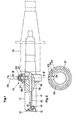
- Fig. 1 shows, partly in section, a side view of the invention applied in a short hole drill.
- Fig. 2 shows a section taken on the line II-II in Fig. 1.
- a housing or swivel joint generally denoted by 10 is mounted on a short hole drill 11, which in conventional manner is seated in the chuck of a drilling machine 18.
- the short hole drill 11 is provided with two indexable cemented carbide cutting inserts 12, 13, which overlap radially.
- the insert 13 has three cutting edges and is secured in cutting position by means of a screw 14.
- the drill 11 is intended for drilling short holes in metallic bodies, preferably with a depth ranging up to twice the hole diameter.
- Cutting fluid for flushing the chips and cooling the cutting surface is supplied through an inner passage 15, which has two openings, one at each of the cutting inserts.
- the chips from a cutting insert 13 is flushed via an outer V-shaped groove, which is formed by radially inwardly directed surfaces 16, 17 on the drill body.
- the passage 15 turns into a transverse passage 19, which is connected to a cutting fluid pump of the drilling machine via the swivel joint 10 and a conduit 20 connected thereto.
- the swivel joint 10 comprises an inner ring 21 and an outer ring 22 which . is rotatable relative to the inner ring.
- the conduit 20 is connected to a bore 23 in the outer ring 22. The communication between the conduit 20 and the passage 19 is ensured whatever the mutual relative rotational position is between the rings 21, 22 due to an annular groove 25 in the outer ring 22.
- the outer ring is provided with a sealing ring on each side of the bore 23 for sealingly engagement with the inner ring 21, and is secured relative to the inner ring by means of a lock ring.
- a radial bore 24 is provided in the inner ring 21.
- a connecting means in form of a nipple 26 is screwed into the passage 19.
- the nipple 26 is provided with a transverse bore 27, by means of which the passage 19 is connected to the bore 24.
- the portion 28 around the opening of the bore 24 is substantially flat.
- the radially outer end of the nipple 26 is conical and intended to cooperate with the portion 28, thereby ensuring that a fluid-tight seal is achieved.
- the nipple 26 When mounting the swivel joint 10 the nipple 26 is first fully screwed into the passage 19; the nipple being provided with an inner socket for a key.
- the inner ring 21 and the outer ring 22 are mutually turned so that the bores 23, 24 are in alignment, whereupon the swivel joint 10 is pushed over the short hole drill 11 so that its bores 23, 24 coincide with the passage 19.
- the nipple 26 is screwed out of the passage 19 so that its conical outer end is forced against the portion 28.
- the invention is of course not limited to the embodiment illustrated in the drawings but is generally applicable in connection with transferring of fluid to rotating units'. Specifically, in cases where the short hole drill is mounted in a holding device which in.its turn is attached to a machine tool, the swivel joint can be mounted on such a holding device.
Abstract
Description
- This invention relates to a device for transferring fluid, such as cooling or flushing medium, to a rotating unit, such as a cutting tool, for example a drill, comprising a housing arranged on the rotating unit. The housing comprises a first member non-rotatably attached to the rotating unit, and a second member which is rotatable relative to the first member. The first and second members are provided with first passages for connecting a fluid source to a second passage in the rotating unit.
- Previously known devices of the above type require that the area on the rotating unit against which the first member rests is completely cylindrical, and that the tolerance on fit between the rotating unit and the first member is, kept. within close limits. In most cases a press-fitting is required in order to achieve a satisfactory connection.
- The object of the present invention is to provide a device for transferring fluid of the above type, which does not require a completely cylindrical mounting area on the rotating unit, and which has very low demands for the tolerance on fit between the members which are non-turnably interconnected.
- The above and other objects have been attained by giving the invention the characterizing features stated in the claims following hereinafter.
- The invention is described in detail in the following with reference to the accompanying drawings in which one embodiment is shown by way of example. It is to be understood that this embodiment is only illustrative of the invention and that various modifications thereof may be made within the scope of the claims.
- In the drawings Fig. 1 shows, partly in section, a side view of the invention applied in a short hole drill.
- Fig. 2 shows a section taken on the line II-II in Fig. 1.
- In Fig. 1 a housing or swivel joint generally denoted by 10 is mounted on a
short hole drill 11, which in conventional manner is seated in the chuck of adrilling machine 18. Theshort hole drill 11 is provided with two indexable cementedcarbide cutting inserts insert 13 has three cutting edges and is secured in cutting position by means of ascrew 14. Thedrill 11 is intended for drilling short holes in metallic bodies, preferably with a depth ranging up to twice the hole diameter. Cutting fluid for flushing the chips and cooling the cutting surface is supplied through aninner passage 15, which has two openings, one at each of the cutting inserts. The chips from acutting insert 13 is flushed via an outer V-shaped groove, which is formed by radially inwardly directedsurfaces - Rearwardly, the
passage 15 turns into atransverse passage 19, which is connected to a cutting fluid pump of the drilling machine via theswivel joint 10 and aconduit 20 connected thereto. - The
swivel joint 10 comprises aninner ring 21 and anouter ring 22 which.is rotatable relative to the inner ring. Theconduit 20 is connected to abore 23 in theouter ring 22. The communication between theconduit 20 and thepassage 19 is ensured whatever the mutual relative rotational position is between therings annular groove 25 in theouter ring 22. - In known manner the outer ring is provided with a sealing ring on each side of the
bore 23 for sealingly engagement with theinner ring 21, and is secured relative to the inner ring by means of a lock ring. Aradial bore 24 is provided in theinner ring 21. - According to the invention a connecting means in form of a
nipple 26 is screwed into thepassage 19. Thenipple 26 is provided with atransverse bore 27, by means of which thepassage 19 is connected to thebore 24. - As shown in Fig. 2, wherein for the sake of clarity the
short hole drill 11 and thenipple 26 have been omitted, theportion 28 around the opening of thebore 24 is substantially flat. The radially outer end of thenipple 26 is conical and intended to cooperate with theportion 28, thereby ensuring that a fluid-tight seal is achieved. - When mounting the
swivel joint 10 thenipple 26 is first fully screwed into thepassage 19; the nipple being provided with an inner socket for a key. Theinner ring 21 and theouter ring 22 are mutually turned so that thebores swivel joint 10 is pushed over theshort hole drill 11 so that itsbores passage 19. Then thenipple 26 is screwed out of thepassage 19 so that its conical outer end is forced against theportion 28. - According to the invention a non-turnable connection between the
inner ring 21 and theshort hole drill 11 is ensured even ; if there is a play between these members. - The invention is of course not limited to the embodiment illustrated in the drawings but is generally applicable in connection with transferring of fluid to rotating units'. Specifically, in cases where the short hole drill is mounted in a holding device which in.its turn is attached to a machine tool, the swivel joint can be mounted on such a holding device.
Claims (7)
Applications Claiming Priority (2)
| Application Number | Priority Date | Filing Date | Title |
|---|---|---|---|
| SE7905152A SE429617B (en) | 1979-06-12 | 1979-06-12 | DEVICE FOR TRANSFER OF FLUID TO A ROTATING UNIT |
| SE7905152 | 1979-06-12 |
Publications (2)
| Publication Number | Publication Date |
|---|---|
| EP0022097A1 true EP0022097A1 (en) | 1981-01-07 |
| EP0022097B1 EP0022097B1 (en) | 1983-10-19 |
Family
ID=20338269
Family Applications (1)
| Application Number | Title | Priority Date | Filing Date |
|---|---|---|---|
| EP80850054A Expired EP0022097B1 (en) | 1979-06-12 | 1980-04-16 | Device for transferring fluid to a rotating member |
Country Status (6)
| Country | Link |
|---|---|
| US (1) | US4293251A (en) |
| EP (1) | EP0022097B1 (en) |
| JP (1) | JPS563109A (en) |
| CA (1) | CA1120914A (en) |
| DE (1) | DE3065351D1 (en) |
| SE (1) | SE429617B (en) |
Cited By (2)
| Publication number | Priority date | Publication date | Assignee | Title |
|---|---|---|---|---|
| EP0095449A1 (en) * | 1982-05-21 | 1983-11-30 | Seco Tools Ab | Device for transferring fluid to a rotating tool holder |
| US6302004B1 (en) * | 1999-03-12 | 2001-10-16 | Aaron Gawain Taylor | Method and apparatus for increasing the productivity of CNC machine tools |
Families Citing this family (14)
| Publication number | Priority date | Publication date | Assignee | Title |
|---|---|---|---|---|
| US4340327A (en) * | 1980-07-01 | 1982-07-20 | Gulf & Western Manufacturing Co. | Tool support and drilling tool |
| JPS59112506U (en) * | 1983-01-19 | 1984-07-30 | 住友電気工業株式会社 | boring tool |
| IT1198610B (en) * | 1983-05-24 | 1988-12-21 | Bakuer Italiana Spa | REFRIGERANT DISTRIBUTOR DEVICE FROM THE OUTSIDE OF THE SPINDLE OF A MACHINE TOOL APPLICABLE ON NUMERIC CONTROL MACHINES AND WORK CENTERS |
| US4890963A (en) * | 1988-06-21 | 1990-01-02 | Carboloy Inc. | Cutting fluid transporting device and cutting tools employing the same |
| SE470547B (en) * | 1992-12-10 | 1994-08-01 | Sandvik Ab | Drill with cooling ducts and means for making drill |
| US5419661A (en) * | 1994-07-25 | 1995-05-30 | Kennametal Inc. | Rotatable tooholder having a stationary, through-center coolant feed system |
| US6220369B1 (en) * | 2000-09-20 | 2001-04-24 | Hey Yeh | Scrap removing and tool cooling device for a front holding end of a tool spindle of a machine tool |
| AU784583B2 (en) * | 2001-07-14 | 2006-05-04 | Hilti Aktiengesellschaft | Support for supporting a power tool on a displacement carriage |
| KR100556681B1 (en) * | 2003-04-28 | 2006-03-07 | 대구텍 주식회사 | tool holder assembly for multifunctional machining |
| US8128323B2 (en) * | 2009-04-14 | 2012-03-06 | Planet Products Corporation | Driven tool assembly |
| AU2013257330B2 (en) | 2012-04-30 | 2017-08-17 | Eigen Systems Limited | Clamp foot air jet apparatus |
| US9346111B2 (en) * | 2013-07-26 | 2016-05-24 | E.R. Shaw Inc. | Machine to manufacture gun barrels and method of using |
| CN104369054B (en) * | 2013-08-17 | 2016-08-10 | 佛山市春日精密机械有限公司 | A kind of milling machine electro spindle detection Multifunctional slip ring |
| US11938551B2 (en) * | 2020-06-18 | 2024-03-26 | Ford Global Technologies, Llc | 3D printed gear cutting tools with capillaries for minimum quantity lubrication, gas or liquid |
Citations (5)
| Publication number | Priority date | Publication date | Assignee | Title |
|---|---|---|---|---|
| GB347218A (en) * | 1930-01-21 | 1931-04-21 | George Harry Gascoigne | An improved method and means for making branch pipe connections |
| US2470218A (en) * | 1945-02-24 | 1949-05-17 | N R Mcnamara | Toolholder |
| GB669111A (en) * | 1949-06-13 | 1952-03-26 | Lucas Ltd Joseph | Improvements relating to pipe joints |
| US3561299A (en) * | 1969-05-06 | 1971-02-09 | Waukesha Cutting Tools Inc | Pulsating coolant adapter |
| US4111468A (en) * | 1975-12-01 | 1978-09-05 | Michael Schneider | Hydraulic boring device |
Family Cites Families (6)
| Publication number | Priority date | Publication date | Assignee | Title |
|---|---|---|---|---|
| US2230881A (en) * | 1939-07-27 | 1941-02-04 | American Brake Shoe & Foundry | Rotary seal |
| US2270927A (en) * | 1940-01-18 | 1942-01-27 | American Brake Shoe & Foundry | Rotary seal |
| US2492025A (en) * | 1946-10-24 | 1949-12-20 | F W Woolworth Co | Collector for money bags and other articles |
| JPS4820076U (en) * | 1971-07-15 | 1973-03-07 | ||
| JPS4823387U (en) * | 1971-07-27 | 1973-03-16 | ||
| GB1449608A (en) * | 1972-10-24 | 1976-09-15 | Weston Co Ltd Charles | Fluid transference apparatus |
-
1979
- 1979-06-12 SE SE7905152A patent/SE429617B/en unknown
-
1980
- 1980-04-16 DE DE8080850054T patent/DE3065351D1/en not_active Expired
- 1980-04-16 EP EP80850054A patent/EP0022097B1/en not_active Expired
- 1980-04-25 US US06/143,858 patent/US4293251A/en not_active Expired - Lifetime
- 1980-04-28 CA CA000350754A patent/CA1120914A/en not_active Expired
- 1980-05-27 JP JP7071280A patent/JPS563109A/en active Granted
Patent Citations (5)
| Publication number | Priority date | Publication date | Assignee | Title |
|---|---|---|---|---|
| GB347218A (en) * | 1930-01-21 | 1931-04-21 | George Harry Gascoigne | An improved method and means for making branch pipe connections |
| US2470218A (en) * | 1945-02-24 | 1949-05-17 | N R Mcnamara | Toolholder |
| GB669111A (en) * | 1949-06-13 | 1952-03-26 | Lucas Ltd Joseph | Improvements relating to pipe joints |
| US3561299A (en) * | 1969-05-06 | 1971-02-09 | Waukesha Cutting Tools Inc | Pulsating coolant adapter |
| US4111468A (en) * | 1975-12-01 | 1978-09-05 | Michael Schneider | Hydraulic boring device |
Cited By (2)
| Publication number | Priority date | Publication date | Assignee | Title |
|---|---|---|---|---|
| EP0095449A1 (en) * | 1982-05-21 | 1983-11-30 | Seco Tools Ab | Device for transferring fluid to a rotating tool holder |
| US6302004B1 (en) * | 1999-03-12 | 2001-10-16 | Aaron Gawain Taylor | Method and apparatus for increasing the productivity of CNC machine tools |
Also Published As
| Publication number | Publication date |
|---|---|
| JPS641247B2 (en) | 1989-01-11 |
| DE3065351D1 (en) | 1983-11-24 |
| SE429617B (en) | 1983-09-19 |
| US4293251A (en) | 1981-10-06 |
| JPS563109A (en) | 1981-01-13 |
| EP0022097B1 (en) | 1983-10-19 |
| CA1120914A (en) | 1982-03-30 |
| SE7905152L (en) | 1980-12-13 |
Similar Documents
| Publication | Publication Date | Title |
|---|---|---|
| EP0022097B1 (en) | Device for transferring fluid to a rotating member | |
| CA1290952C (en) | Downhole motor drive shaft universal joint assembly | |
| US5099882A (en) | Pressure balanced hydraulic coupling with metal seals | |
| US4754780A (en) | Pressure balanced hydraulic coupling | |
| US6827160B2 (en) | Downhole mud motor | |
| US5358360A (en) | Device for supplying fluid to tool | |
| US4635736A (en) | Drill steering apparatus | |
| US4219618A (en) | Dental hand tool holder | |
| US6520253B2 (en) | Rotating drilling head system with static seals | |
| US2266383A (en) | Well bore deflecting tool | |
| US4585256A (en) | Side feed water swivel | |
| US4785693A (en) | Hydraulic torque wrench | |
| WO1999064711A3 (en) | Improved backhead and check valve for down-hole drills | |
| CA1318904C (en) | Plugable safety coupling, in particular for pressure air lines | |
| EP0083888B1 (en) | Coupling attachment of a member on a shaft | |
| US5326072A (en) | Plug-in safety coupling, in particular for compressed air lines | |
| US5121947A (en) | Expansion sealing device | |
| EP0072657A1 (en) | An attachment for fitting to a drive spindle of a machine | |
| CN1102874C (en) | Hole drilling device | |
| US5637037A (en) | Method and grinding cup for grinding buttons of a rock drilling bit | |
| EP0051993A1 (en) | Blocked ball valve | |
| CA2487896A1 (en) | Drilling attachment | |
| US4621790A (en) | Butterfly valve | |
| KR930004810B1 (en) | Adapter assembly | |
| GB2213912A (en) | Fluid flow control valve |
Legal Events
| Date | Code | Title | Description |
|---|---|---|---|
| PUAI | Public reference made under article 153(3) epc to a published international application that has entered the european phase |
Free format text: ORIGINAL CODE: 0009012 |
|
| AK | Designated contracting states |
Designated state(s): DE FR GB IT |
|
| 17P | Request for examination filed |
Effective date: 19810511 |
|
| ITF | It: translation for a ep patent filed |
Owner name: BARZANO' E ZANARDO MILANO S.P.A. |
|
| GRAA | (expected) grant |
Free format text: ORIGINAL CODE: 0009210 |
|
| AK | Designated contracting states |
Designated state(s): DE FR GB IT |
|
| REF | Corresponds to: |
Ref document number: 3065351 Country of ref document: DE Date of ref document: 19831124 |
|
| ET | Fr: translation filed | ||
| PLBE | No opposition filed within time limit |
Free format text: ORIGINAL CODE: 0009261 |
|
| STAA | Information on the status of an ep patent application or granted ep patent |
Free format text: STATUS: NO OPPOSITION FILED WITHIN TIME LIMIT |
|
| 26N | No opposition filed | ||
| ITTA | It: last paid annual fee | ||
| PGFP | Annual fee paid to national office [announced via postgrant information from national office to epo] |
Ref country code: GB Payment date: 19980407 Year of fee payment: 19 |
|
| PGFP | Annual fee paid to national office [announced via postgrant information from national office to epo] |
Ref country code: FR Payment date: 19980409 Year of fee payment: 19 |
|
| PGFP | Annual fee paid to national office [announced via postgrant information from national office to epo] |
Ref country code: DE Payment date: 19980424 Year of fee payment: 19 |
|
| PG25 | Lapsed in a contracting state [announced via postgrant information from national office to epo] |
Ref country code: GB Free format text: LAPSE BECAUSE OF NON-PAYMENT OF DUE FEES Effective date: 19990416 |
|
| GBPC | Gb: european patent ceased through non-payment of renewal fee |
Effective date: 19990416 |
|
| PG25 | Lapsed in a contracting state [announced via postgrant information from national office to epo] |
Ref country code: FR Free format text: LAPSE BECAUSE OF NON-PAYMENT OF DUE FEES Effective date: 19991231 |
|
| REG | Reference to a national code |
Ref country code: FR Ref legal event code: ST |
|
| PG25 | Lapsed in a contracting state [announced via postgrant information from national office to epo] |
Ref country code: DE Free format text: LAPSE BECAUSE OF NON-PAYMENT OF DUE FEES Effective date: 20000201 |