EP0022060A1 - Pocket calculator for family planning - Google Patents
Pocket calculator for family planning Download PDFInfo
- Publication number
- EP0022060A1 EP0022060A1 EP80810166A EP80810166A EP0022060A1 EP 0022060 A1 EP0022060 A1 EP 0022060A1 EP 80810166 A EP80810166 A EP 80810166A EP 80810166 A EP80810166 A EP 80810166A EP 0022060 A1 EP0022060 A1 EP 0022060A1
- Authority
- EP
- European Patent Office
- Prior art keywords
- probe
- calculator
- temperature
- sensor
- memory
- Prior art date
- Legal status (The legal status is an assumption and is not a legal conclusion. Google has not performed a legal analysis and makes no representation as to the accuracy of the status listed.)
- Granted
Links
Images


Classifications
-
- A—HUMAN NECESSITIES
- A61—MEDICAL OR VETERINARY SCIENCE; HYGIENE
- A61B—DIAGNOSIS; SURGERY; IDENTIFICATION
- A61B10/00—Other methods or instruments for diagnosis, e.g. instruments for taking a cell sample, for biopsy, for vaccination diagnosis; Sex determination; Ovulation-period determination; Throat striking implements
- A61B10/0012—Ovulation-period determination
-
- A—HUMAN NECESSITIES
- A61—MEDICAL OR VETERINARY SCIENCE; HYGIENE
- A61B—DIAGNOSIS; SURGERY; IDENTIFICATION
- A61B5/00—Measuring for diagnostic purposes; Identification of persons
- A61B5/0002—Remote monitoring of patients using telemetry, e.g. transmission of vital signals via a communication network
- A61B5/0004—Remote monitoring of patients using telemetry, e.g. transmission of vital signals via a communication network characterised by the type of physiological signal transmitted
- A61B5/0008—Temperature signals
-
- A—HUMAN NECESSITIES
- A61—MEDICAL OR VETERINARY SCIENCE; HYGIENE
- A61B—DIAGNOSIS; SURGERY; IDENTIFICATION
- A61B10/00—Other methods or instruments for diagnosis, e.g. instruments for taking a cell sample, for biopsy, for vaccination diagnosis; Sex determination; Ovulation-period determination; Throat striking implements
- A61B10/0012—Ovulation-period determination
- A61B2010/0019—Ovulation-period determination based on measurement of temperature
Definitions
- the invention relates to a calculator for family planning, as well as a thermometric probe intended for this calculator.
- the calculator must have a permanent random access memory (RAM) for the data allowing the application of the method, these data concerning the dates of the catamenial periods of the interested person as well as the graph of his temperature day by day. These data must be provided for a few cycles for the method to be applicable and allow the dates of the next cycle to be predicted.
- RAM permanent random access memory
- One solution is to take the temperature using a conventional mercury medical thermometer and then transfer the result to the calculator's keyboard to save it in memory.
- this solution has the disadvantage of a significant risk of human error when writing the data on the keyboard.
- the present invention aims to make it easier to acquire temperature data and to avoid a risk of human transcription error.
- the invention therefore aims to provide a pocket calculator designed to apply a family planning method and provided with a thermometric probe to make the acquisition of temperature data simple and secure, this probe having to operate without being connected by wire and avoiding the need for manual digital temperature transcription and thereby avoiding the risk of human error.
- the invention also aims to provide a thermometric probe intended for a calculator of the abovementioned type.
- the invention proposes the calculator and the probe defined, respectively, in claims 1 and 7.
- the calculator shown in fig. 1 comprises a box 1 comprising the circuits, not shown, and on which the display means 4, 5 are seen, surrounded by inscriptions 3, 6, and control keys 7, 8.
- the digital display 5 and the numeric keys 8 are similar to the corresponding parts of an ordinary four-operation calculator.
- the upper part 4 of the display has three zones, each arranged opposite an inscription on the inscription line 3.
- This part 4 of the display is intended to indicate the result of a forecast calculation applying a family planning method.
- the display shows the probability that an intimate relationship, on a given date, will be followed by pregnancy. Display 4 is used to indicate whether the probability is high, medium or zero.
- the digital part 5 of the display makes it possible to display the data and the arithmetic results related to the use as an ordinary calculator with four operations and to the manipulation of the digital keyboard 8.
- this digital display 5 also makes it possible to display a date, the two digits on the left giving the day, the next digit being not activated, the next two digits giving the month, the next digit being not activated, and the last two digits indicating the year.
- This digital part also makes it possible to display the current time, a flashing or scrolling of the seconds making it possible to distinguish the display of the time from the display of a date.
- the 9 "H” key is used to control the display of the time and the other keys 10 to 13 relate more specifically to the use of the calculator for the application of a planning method. family.
- the key 10 "D” controls the display of the date and also allows the recording of another date, for which the execution of a forecast calculation is ordered.
- Keys 11 and 12 are used to note the date of the period in memory.
- this date is that of the same day, it can be displayed on display 5 by simple call using the "D" key. If it is another date, you can enter this other date using the numeric keypad by pressing D after the month numbers, day numbers and year numbers. The date is displayed. The keys 11 and 12 are then pressed simultaneously and the date is then recorded as the date of the start of the rules. This operation modifies the data; this is why it has been provided that its registration requires the simultaneous action on two keys to reduce the risks of inadvertence. The date is displayed in Anglo-Saxon format, that is to say month, day, year, in correspondence with the inscriptions 5. But it is obvious that we can provide other formats, in particular the European format , inscriptions 3 and 5 being translated into the desired language.
- the key 13 " * " makes it possible to control the calculation of a forecast for the date displayed on the digital display 5, the result appearing on the upper display 4; double action on the same " * " key allows to control the calculation of a forecast giving the interval around an ovulation during which the probabilities of a pregnancy are maximum.
- the two extreme dates are displayed alternately with a period of one to two seconds.
- the calculator has a housing 25 for the temperature probe 15 of FIG. 2.
- the housing comprises a retaining spring 26 intended to cooperate with an annular retaining groove 20 formed on the periphery of the body 16 of the probe 15.
- the housing 25 also comprises contacts 27 intended to cooperate with annular contacts 21 arranged on the probe body.
- the bottom of the housing 25 is occupied by an axially movable bush 28 having a conical opening 29, and intended to receive the thin part 17 of the probe 15 at the end of which is the sensor 18 of the probe. Note that the length of the socket cavity is greater than the length of the thin part 17 of the probe so that the sensor 18 does not touch the bottom of the cavity, the probe being retained by the shoulder 17 'at the level of the conical opening 29.
- the body 16 is cylindrical and longer than the thin part, so that when the probe is inserted into its housing, the thin part is opposite the conical opening without abut on the edges of this opening.
- the sleeve 28 is axially movable and cooperates with a ratchet and spring mechanism 30 similar to that existing in a ballpoint pen and arranged in such a way that when the sensor is in place and that it is pressed about 2 mm into its housing, the mechanism 30 reacts by pushing the sleeve and therefore the probe, so that it can be grasped and extracted from its housing for use.
- the probe When the probe is at rest in its housing, it is just flush with the surface of the housing.
- On the probe itself there is also a humidity sensor 19 making it possible to detect the contact of a mucous membrane.
- the upper face of the calculator shown in fig. 3, shows the end of the probe 15, and also shows an external connector 32 with several contacts, arranged in a cavity 33.
- the cavity is in principle masked by a cover comprising a retaining tongue cooperating with a retaining groove 34.
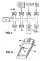
- the calculator has a microprocessor system configuration shown in FIG. 8, some parts of which are conventional.
- the system includes a processor 40 connected by a bus 41 to memories and peripherals.
- memories there is a ROM memory 42 for the programs and the fixed data of the RAM memory 42, a special memory 45 with bistable electromechanical relays, ⁇ with its interface 44.
- ROM memory 42 for the programs and the fixed data of the RAM memory 42
- a special memory 45 with bistable electromechanical relays ⁇ with its interface 44.
- the relays used are miniaturized relays with high immunity to acceleration and to various environments and, above all, retaining the memorized information even if the power is cut.
- the system represented also comprises a time measurement unit 47 operating with a quartz 48.
- the system comprises the peripherals constituted by the keyboard comprising the keys 7, 8, and the display devices 4, 5, for example of the LCD type ( liquid crystal), with their respective interfaces 50, 51.
- the system comprises the probe connector 52 including the contacts 27 of the probe housing, with the interface 51, and the external connector 32 with its interface 46.
- the apparatus of fig. 5 is intended to perform certain control operations on the calculator.
- a device is intended for a gynecologist or a competent person from a family planning center.
- initialization requires certain start-up operations which it is not advisable to leave to the interested person, because the purpose of the calculator is to make it simple to apply a method, while the start-up operations are a bit tricky.
- the device allows access to the stored content, for example to establish the graph of temperatures from day to day, which provides the gynecologist with a useful indication for a consultation.
- One of the start-up operations concerns setting the time and date after the calculator has been fitted with its power supply batteries.
- the person using the calculator cannot, in principle, carry out this operation himself, which is done only once for the service life of the batteries; indeed, if the time setting was possible in normal use, it could be that inadvertently the person alters the data by mistakenly entering an incorrect date, as a result of which the forecasts would be distorted.
- the apparatus 55 includes a housing 56 intended to receive a calculator of the type described above.
- a connector 57 is provided to cooperate with the external connector 32 of the calculator.
- the apparatus comprises a display 58, control keys 60 and a printer 59 making it possible, for example, to establish the graph of the temperatures day by day from the data stored in the calculator.
- the device also allows the time and date of the calculator to be set, for example according to the following principle.
- the system includes a fixed program in ROM allowing the imposition of time and date content on the time measurement unit, this from orders given from the numeric keypad 8, but only on the condition that the calculator is connected to a control device 55, and that an appropriate key has been pressed on said control device, this key acting on the microprocessor system via the external connector 32 and its interface 46.
- Fig. 6a illustrates another embodiment of the calculator, distinguished by a simpler keyboard and which is not intended to be connected to a control device.
- the housing 1 there is a special display 4 formed of three electro-optical elements 121, 122, 123, respectively red, yellow and green, intended to indicate the result of a forecast calculation according to the following convention: high probability, red ; medium, yellow; zero, green.
- the digital display 5 displays the time, a date or a temperature.
- the "H” key 134 is used to control the display of the current time and the “D” key 133 is used to control the display of the current date, the " * " 128 key is used to control a forecast calculation for this date or, by double action, the calculation of the interval around ovulation when the probability of pregnancy is maximum.
- the keys "J", “M” and “A” 124, 125 and 126 allow the date displayed to be changed.
- Pressing one of the keys increases the corresponding number, ie the day for the "J” key, the month for the "M” key and the year for the "A” key.
- the key 127 makes it possible to reverse the direction of the action of the keys 124 to 126 which, then, cause the respective digits to decrease.
- the keys 129, 130 allow the date displayed to be entered as the date of the first day of periods.
- Fig. 6b partially shows the back of the calculator with the housing 140 for the batteries 141, this housing also comprising a special control key 142.
- This key 142 is normally inaccessible, being hidden by the cover of the battery compartment. This key is intended to allow certain control or adjustment operations carried out in principle by a person specially trained in a family planning center, or the gynecologist of the person concerned.
- Pressing these keys activates a program provided for setting the time and date on the calculator when it starts up, as well as accessing the memory, at least to read the contents. stored which appear on display 5 for example according to the procedure and according to the format described below.
- the calculator is held in one hand, the battery housing 140 being exposed, which gives access to the keys 142 to one of the fingers of the hand holding the calculator.
- the other hand remains free to act on the keyboard.
- the "T" key 135 is pressed and the display 9 then shows the oldest stored temperature, alternately with its date, and when the "T" key is pressed again, The display shows the temperature for the next day alternately with its date, and so on, which allows the temperature graph to be established.
- the letter "r" is displayed with the temperature, and for the dates of an interval around ovulation, the light element 121 is on.
- Fig. 7 shows an example of an electrical diagram for a temperature probe intended for a pocket calculator for family planning.
- the sensor 18 is, during the measurement, brought to the temperature to be measured T X.
- the sensor here is formed by an NTC 85 resistance, for example of 600 kw, with a characteristic of 5% / °, that is to say 30 kw / o around its value. nominal.
- This NTC is connected to the circuit of a relaxation oscillator 81 formed by a reversing trigger 87 and an RC network comprising a capacitor 88 and a resistor 86 in parallel with the NTC 85.
- the resistor 86 is not essential, in particular in the case where the resistance NTC 85 has a very linear characteristic in the useful range.
- the oscillator 81 delivers logic pulses at frequency f x depending on the temperature T. These pulses pass, via an AND gate 89 into a counter 90.
- the circuit comprises a reference oscillator 82 of construction similar to the first oscillator and adjacent to it.
- This oscillator comprises a reversing trigger 93 and an RC network with capacity 94 and resistance 92.
- the reference oscillator 82 has a frequency f r of the same order of magnitude as f, for example celebrating the geometric mean between the maximum and the minimum of the useful domain of f.
- This frequency f is brought, via an AND gate 95 to a divider 96 which divides it by a number representing the inverse of the relative precision sought for the measurement.
- the divider 96 ends with a flip-flop 107 whose inverted output controls the AND gates 89 and 95, and whose non-inverted output controls two successive monostable flip-flops 98 and 99, the first serving for recording the counting result and the second used for resetting.
- the output of the second flip-flop 99 leads to OR gates 190 and 196 which control the zero-setting inputs of the counter 90 and the divider 96 respectively.
- the counter 90 is connected to a memory 100 and to a first input of a comparator 101, the second input of this comparator being connected to the memory 100.
- the memory 100 includes a "serial" output line and a synchronization line for the "serial" transfer connected respectively at terminals 103 and 102.
- the circuit also has a control and power supply unit 106 connected to terminals 109, 105, terminals 102 to 105 terminating in the annular contacts 21 of the probe.
- block 106 In addition to its power supply function, block 106 has an initial reset function for counter 90, divider 96 and memory 100. To this end, block 106 controls a monostable flip-flop 108 whose output is linked to a memory reset input 100 and to OR gates 190 and 196 controlling the reset input of counter 90 and divider 96 respectively.
- the terminals 104 and 105 allow the loading of the supply battery from the calculator, the circuit 106 being arranged to deactivate the other elements of the circuit of FIG. 7 as long as the probe is connected to the calculator.
- the probe is removed for a temperature measurement, its circuits are put into operation, the counter, the divider and the memory being initialized to zero.
- the two oscillating circuits deliver their frequencies f and f respectively.
- the divider 96 has completed a cycle, its final stage 107 is set to 1 and the line 97 inhibits the gates 89 and 95, which blocks the counting.
- the monostable sends a control pulse activating the comparator 101.
- a monostable 99 sends a pulse resetting the counter 90 and the divider 96, including its terminal stage 97, which again activates the doors 89 and 95, so that a new measurement cycle begins.
- the action of the comparator has the effect that it is this latter value which is recorded.
- the probe thus functions as a maximum thermometer.
- the advantage of this arrangement is as follows: when the person withdraws the probe after having taken his temperature and that consequently the temperature of the sensor returns to the temperature of the ambient air, the rectal temperature, higher, remains recorded.
- the microprocessor system can read the memorized result via terminals 102 and 103. Terminal 102 transmits synchronization pulses and terminal 103 transmits in sequence the binary values representing the contents of memory 100 .
- the reference oscillator 82 is close to the measurement oscillator 81 and quite similar to it, with the exception of the NTC element 85 of course.
- they receive their food from the same source. Being neighbors, they are in principle at the same temperature T. Consequently, if the frequency af of the first oscillator, a function of the temperature T x , is further influenced by a thermal drift or a supply drift acting on the circuit 81, it can be expected that the reference frequency f is affected in the same direction and by the same drift acting on the reference oscillator 82. Consequently, if such a drift slows down for example f, it will slow down f in the same proportion, which will lengthen the counting time, by so that finally the effect of the drift will be canceled.
- the logic part of the circuit of fig. 7 is constructed from relatively simple elements such as as counters, doors, registers. However, for the circuit functions of fig. 7, or a fortiori for more complex functions, it may be preferable to immediately call on a microprocessor.
- a measurement oscillator 81 connected to a sensor 18, and a reference oscillator 82, which are connected to a control circuit 80 which may be a microprocessor.
- the circuit is connected to a connector leading to the annular contacts 21.
- the circuit of FIG. 8 may include a humidity detector 19.
- the temperature to be measured is in principle the rectal temperature and the purpose of the humidity detector is to provide an indication of contact with the wall of the rectum, moist enough to cause an appropriate detector to react.
- the signal therefore provides an additional indication as to the validity of the measurement.
- the temperature should be taken upon waking.
- the time can therefore be used as a condition for a valid measurement. This condition is obviously verified by the calculator system, which consults its unit of time measurement when the probe is replaced after being taken out.
- the system can arrange the system for example so that it considers as invalid a measurement of the temperature carried out on the same day as a first measurement, or at a time too far away from the usual time of awakening, or also a temperature outside the range of physiological temperatures.
- the program can also be refined to the point of differentiating between the temperature change linked to the catamenial cycle, and a temporary temperature change of pathological origin such as a slight fever or a slight hypothermia. It is obvious that a disease can make the method inapplicable. These criteria are applied by the calculator system.
- time-delay means can be provided on the probe itself.
- Fig. 9 shows a probe circuit provided with a timing means.
- the circuit includes a sensor 18 connected to a measurement oscillator 81 whose output is connected to a counter 90, and a reference oscillator 82 whose output is connected to a frequency divider 96.
- the divider 96 is followed by a divider 110 with three binary stages. The inverted output of the first of these stages and the normal outputs of the other two are connected to the inputs of a multiple AND gate 111 whose output 112 leads to a control circuit 113.
- This circuit controls the counter 90 via line 114.
- the counter 90 is further arranged so that it can be read in serial mode using a read line 117 and a synchronization line 116.
- the operation is as follows. Initially, the counter 90 and the dividers 96 and 110 are at zero. The period on leaving the divider 96 is assumed, for example, to be 10 seconds. The output 112 of the gate 11 is in the state "1" when the counter 110 is in the state "6" or "1 1 O” in binary, this state having a duration of 10 seconds and taking place between the 60 th and the 70 th second after the start of operation.
- the circuit 113 is arranged to activate the counter 90, via the line 114, exactly during the time when the line 112 is at "1", after which it deactivates the oscillators; when the probe is returned to its housing, the circuit 113 manages the transfer of the number counted by the counter 90 to the system of the calculator.
- the reference oscillator 82 is used not only as a time base for the duration of the counting, which allows the measurement of f relative to f r , but also as a time base for a time delay.
Abstract
Description
L'invention concerne une calculatrice pour le planning familial, ainsi qu'une sonde thermométrique destinée à cette calculatrice.The invention relates to a calculator for family planning, as well as a thermometric probe intended for this calculator.
On sait actuellement réaliser des calculatrices miniatures capables d'effectuer des calculs relativement complexes.We currently know how to make miniature calculators capable of performing relatively complex calculations.
On connait d'autre part des méthodes de planning familial telles que par exemple la méthode Ogino. La mise au point d'un programme de calcul pour l'application de cette méthode et l'incorporation d'un tel programme à une calculatrice de poche sous la forme notamment d'une ROM (mémoire morte à relecture seulement) n'offre en principe aucune difficulté.We also know family planning methods such as for example the Ogino method. The development of a calculation program for the application of this method and the incorporation of such a program into a pocket calculator in the form in particular of a ROM (read-only read-only memory) does not offer principle no difficulty.
Cependant la calculatrice doit posséder une mémoire vive (RAM) permanente pour les données permettant l'application de la méthode, ces données concernant les dates des périodes cataméniales de la personne intéressée ainsi que le graphe de sa température jour par jour. Ces données doivent être fournies pendant quelques cycles pour que la méthode soit applicable et permette de prévoir les dates du prochain cycle.However the calculator must have a permanent random access memory (RAM) for the data allowing the application of the method, these data concerning the dates of the catamenial periods of the interested person as well as the graph of his temperature day by day. These data must be provided for a few cycles for the method to be applicable and allow the dates of the next cycle to be predicted.
La conservation de ces données en mémoire implique l'utilisation de mémoires particulières dont le contenu ne se perd pas lorsque l'alimentation est coupée. La demande suisse 8455/78 traite de ce problème.The conservation of this data in memory implies the use of particular memories whose content is not lost when the power is cut. Swiss application 8455/78 addresses this problem.
Un autre problème rencontré concerne l'acquisition des données de température. Une solution envisagée consiste à prendre la température à l'aide d'un thermomètre médical à mercure classique et de reporter ensuite le résultat sur le clavier de la calculatrice pour l'inscrire dans la mémoire. Cependant, cette solution présente l'inconvénient d'un risque sensible d'erreur humaine au moment de l'inscription de la donnée sur le clavier. La présente invention vise à rendre plus aisée l'acquisition d'une donnée dé température et à éviter un risque d'erreur humaine de transcription.Another problem encountered concerns the acquisition of temperature data. One solution is to take the temperature using a conventional mercury medical thermometer and then transfer the result to the calculator's keyboard to save it in memory. However, this solution has the disadvantage of a significant risk of human error when writing the data on the keyboard. The present invention aims to make it easier to acquire temperature data and to avoid a risk of human transcription error.
L'invention vise donc à fournir une calculatrice de poche prévue pour appliquer une méthode de planning familial et munie d'une sonde thermométrique pour rendre simple et sûre l'acquisition des données de température, cette sonde devant fonctionner sans être-reliée par fil et évitant la nécessité d'une transcription numérique manuelle de la température et évitant par là un risque d'erreur humaine.The invention therefore aims to provide a pocket calculator designed to apply a family planning method and provided with a thermometric probe to make the acquisition of temperature data simple and secure, this probe having to operate without being connected by wire and avoiding the need for manual digital temperature transcription and thereby avoiding the risk of human error.
L'invention vise également à fournir une sonde thermométrique destinée à une calculatrice du genre sus- mensionné.The invention also aims to provide a thermometric probe intended for a calculator of the abovementioned type.
A cette fin, l'invention propose la calculatrice et la sonde définies, respectivement, dans les revendications 1 et 7.To this end, the invention proposes the calculator and the probe defined, respectively, in
L'invention sera mieux comprise à l'aide de la description de quelques formes d'exécution faites ci-après en référence aux dessins sur lesquels :
- La fig. 1 représente une calculatrice de poche pour le planning familial,
- la fig. 2 représente une sonde thermométrique destinée à la calculatrice de la fig. 1,
- la fig. 3 représente une vue de la face étroite supérieure de la calculatrice,
- la fig. 4 représente une configuration de système à microprocesseur pour la calculatrice,
- la fig. 5 représente un appareil de contrôle,
- la fig. 6a représente une autre forme de réalisation de la calculatrice, et
- la fig. 6b est une vue de dos d'une partie de la calculatrice de la fig. 1,
- la fig. 7 représente les circuits d'une sonde thermométrique,
- la fig. 8 représente de manière schématique les circuits d'une sonde thermométrique, et
- la fig. 9 représente'une autre forme de réalisation des circuits d'une sonde thermométrique.
- Fig. 1 represents a pocket calculator for family planning,
- fig. 2 represents a thermometric probe intended for the calculator of FIG. 1,
- fig. 3 represents a view of the upper narrow face of the calculator,
- fig. 4 represents a microprocessor system configuration for the calculator,
- fig. 5 shows a recording device,
- fig. 6a shows another embodiment of the calculator, and
- fig. 6b is a back view of part of the calculator of FIG. 1,
- fig. 7 represents the circuits of a thermometric probe,
- fig. 8 schematically represents the circuits of a thermometric probe, and
- fig. 9 shows another embodiment of the circuits of a thermometric probe.
La calculatrice représentée à la fig. 1 comporte un boitier 1 comprenant les circuits, non représentés, et sur lequel on voit les moyens d'affichage 4, 5, entourés d'inscriptions 3, 6, et des touches de commande 7, 8.The calculator shown in fig. 1 comprises a
L'affichage numérique 5 et les touches numériques 8 sont semblables aux parties correspondantes d'une calculatrice ordinaire à quatre opérations. La partie supérieure 4 de l'affichage comporte trois zones disposées chacune en regard d'une inscription de la ligne 3 d'inscription. Cette partie 4 de l'affichage est destinée à indiquer le résultat d'un calcul de prévision appliquant une méthode de planning familial. L'affichage indique la probabilité pour qu'un rapport intime, à une date donnée, soit suivi d'une grossesse. L'affichage 4 permet d'indiquer si la probabilité est élevée, moyenne ou nulle.The
La partie numérique 5 de l'affichage permet d'afficher les données et les résultats arithmétiques liés à l'utilisation comme calculatrice ordinaire à quatre opérations et à la manipulation du clavier numérique 8. Cependant, cet affichage numérique 5 permet également d'afficher une date, les deux digits de gauche donnant le jour, le digit suivant étant non activé, les deux digits suivants donnant le mois, le digit d'après étant non activé, et les deux derniers digits indiquant l'année. Cette partie numérique permet également d'afficher l'heure présente, un clignotement ou le défilement des secondes permettant de distinguer l'affichage de l'heure de l'affichage d'une date.The
Parmi les touches de la rangée 7, la touche 9 "H" permet de commander l'affichage de l'heure et les autres touches 10 à 13 concernent plus spécifiquement l'utilisation de la calculatrice pour l'application d'une méthode de planning familial. La touche 10 "D" commande l'affichage de la date et permet également l'inscription d'une autre date, pour laquelle on ordonne l'exécution d'un calcul de prévision. Les touches 11 et 12 permettent de noter en mémoire la date des règles.Among the keys in
Si cette date est celle du jour même, on peut la faire apparaître sur l'affichage 5 par simple appel au moyen de la touche "D". Si c'est une autre date, on peut introduire cette autre date à l'aide du clavier numérique en pressant D après les chiffres du mois, les chiffres du jour et les chiffres de l'année. La date est affichée. On enfonce alors simultanément les touches 11 et 12 et la date est alors enregistrée en tant que date du début des règles. Cette opération modifie les données; c'est pourquoi il a été prévu que son inscription nécessite l'action simultanée sur deux touches pour réduire les risques d'une inadvertance. La date est affichée selon le format anglo-saxon, c'est-à-dire mois, jour, an, en correspondance avec les inscriptions 5. Mais il est évident que l'on peut prévoir d'autres formats, notamment le format européen, les inscriptions 3 et 5 étant traduites dans la langue voulue.If this date is that of the same day, it can be displayed on
La touche 13 "*" permet de commander le calcul d'une prévision pour la date affichée sur l'affichage numérique 5, le résultat apparaissant sur l'affichage supérieur 4; une double action sur la même touche "*" permet de commander le calcul d'une prévision donnant l'intervalle autour d'une ovulation pendant lequel les probabilités d'une grossesse sont maximales. Les deux dates extrêmes sont affichées alternativement avec une période d'une à deux secondes.The key 13 " * " makes it possible to control the calculation of a forecast for the date displayed on the
La calculatrice comporte un logement 25 pour la sonde thermométrique 15 de la fig. 2. Le logement comporte un ressort de retenue 26 destiné à coopérer avec une rainure annulaire de retenue 20 ménagée sur le pourtour du corps 16 de la sonde 15. Le logement 25 comporte aussi des contacts 27 destinés à coopérer avec des contacts annulaires 21 disposés sur le corps de la sonde. Le fond du logement 25 est occupé par une douille mobile axialement 28 comportant une ouverture conique 29, et destinée à recevoir la partie mince 17 de la sonde 15 au bout de laquelle se trouve le capteur 18 de la sonde. On remarque que la longueur de la cavité de la douille est supérieure à la longueur de la partie mince 17 de la sonde afin que le capteur 18 ne touche pas le fond de la cavité, la sonde étant retenue par l'épaulement 17' au niveau de l'ouverture conique 29. On remarque également que le corps 16 est cylindrique et plus long que la partie mince, de manière que lorsqu'on introduit la sonde dans son logement, la partie mince se présente en regard de l'ouverture conique sans buter sur les bords de cette ouverture. La douille 28 est mobile axialement et coopère avec un mécanisme à cliquet et à ressort 30 analogue à celui existant dans un stylo bille et agencé de telle sorte que lorsque le capteur est en place et qu'on l'enfonce d'environ 2 mm dans son logement, le mécanisme 30 réagisse en repoussant la douille et donc la sonde, de manière qu'on puisse la saisir et l'extraire de son logement en vue d'une utilisation. Lorsque la sonde est au repos dans son logement, elle affleure juste la surface du boîtier. Sur la sonde elle-même on remarque également un capteur d'humidité 19 permettant de détecter le contact d'une muqueuse.The calculator has a
La face supérieure de la calculatrice, représentée à la fig. 3, montre l'extrémité de la sonde 15, et montre aussi un connecteur extérieur 32 à plusieurs contacts, disposé dans une cavité 33. La cavité est en principe masquée par un couvercle comportant une languette de retenue coopérant avec une rainure de retenue 34.The upper face of the calculator, shown in fig. 3, shows the end of the
La calculatrice présente une configuration de système à microprocesseur représentée à la-fig. 8, dont certaines parties sont classiques. Le système comporte un processeur 40 relié par un bus 41 à des mémoires et à des périphériques. Parmi les mémoires on trouve une mémoire ROM 42 pour les programmes et les données fixes de la mémoire RAM 42, une mémoire spéciale 45 à relais électromécaniques bistables, `avec son interface 44. On trouve un exemple d'une telle mémoire dans la demande suisse 8455/78 précédemment mentionnée.The calculator has a microprocessor system configuration shown in FIG. 8, some parts of which are conventional. The system includes a
Les relais utilisés sont des relais miniaturisés présentant une grande immunité aux accélérations et à divers environnements et, surtout, conservant l'information mémorisée même si l'alimentation est coupée.The relays used are miniaturized relays with high immunity to acceleration and to various environments and, above all, retaining the memorized information even if the power is cut.
Le système représenté comprend encore une unité de mesure du temps 47 fonctionnant avec un quartz 48. Le système comprend les périphériques constitués par le clavier comprenant les touches 7, 8, et les dispositifs d'affichage 4, 5, par exemple du type LCD (à cristaux liquides), avec leurs interfaces respectifs 50, 51. Le système comprend enfin le connecteur de sonde 52 incluant les contacts 27 du logement de sonde, avec l'interface 51, et le connecteur extérieur 32 avec son interface 46.The system represented also comprises a
L'appareil de la fig. 5 est destiné à effectuer certaines opérations de contrôle sur la calculatrice. En principe un tel appareil est destiné à un gynécologue ou à une personne compétente d'un centre de planning familial. Lorsqu'une personne acquiert une calculatrice, l'initialisation nécessite certaines opérations de mise en route qu'il n'est pas indiqué de laisser faire à la personne intéressée, car le but de la calculatrice est de rendre simple l'application d'une méthode, alors que les opérations de mise en route sont un peu délicates. D'autre part, l'appareil permet d'accéder au contenu mémorisé, pour établir par exemple le graphe des températures au jour le jour, ce qui fournit au gynécologue une indication utile pour une consultation. Une des opérations de mise en route concerne la mise à l'heure et à la date après que la calculatrice a été munie de ses batteries d'alimentation. Il est préférable que la personne utilisant la calculatrice ne puisse pas, en principe, procéder elle-même à cette opération qui est faite une seule fois pour la durée de service des batteries; en effet, si la remise à l'heure était possible en utilisation normale, il se pourrait que par inadvertance la personne altère les données en introduisant par erreur une date erronée, en suite de quoi les prévisions seraient faussées.The apparatus of fig. 5 is intended to perform certain control operations on the calculator. In principle, such a device is intended for a gynecologist or a competent person from a family planning center. When a person acquires a calculator, initialization requires certain start-up operations which it is not advisable to leave to the interested person, because the purpose of the calculator is to make it simple to apply a method, while the start-up operations are a bit tricky. On the other hand, the device allows access to the stored content, for example to establish the graph of temperatures from day to day, which provides the gynecologist with a useful indication for a consultation. One of the start-up operations concerns setting the time and date after the calculator has been fitted with its power supply batteries. It is preferable that the person using the calculator cannot, in principle, carry out this operation himself, which is done only once for the service life of the batteries; indeed, if the time setting was possible in normal use, it could be that inadvertently the person alters the data by mistakenly entering an incorrect date, as a result of which the forecasts would be distorted.
L'appareil 55 comporte un logement 56 destiné à recevoir une calculatrice du type précédemment décrit. Dans le logement, un connecteur 57 est prévu pour coopérer avec le connecteur externe 32 de la calculatrice. L'appareil comporte un affichage 58, des touches de commande 60 et une imprimante 59 permettant par exemple d'établir le graphique des températures jour par jour à partir des données mémorisées dans la calculatrice. L'appareil permet également la mise à l'heure et à la date de la calculatrice, par exemple selon le principe suivant.The
Le système comporte un programme fixe en ROM permettant d'imposer un contenu d'heure et de date à l'unité de mesure du temps, cela à partir d'ordres donnés depuis le clavier numérique 8, mais uniquement à la condition que la calculatrice soit connectée à un appareil de contrôle 55, et que l'on ait actionné une touche adéquate sur le dit appareil de contrôle, cette touche agissant sur le système à microprocesseur via le connecteur externe 32 et son interface 46.The system includes a fixed program in ROM allowing the imposition of time and date content on the time measurement unit, this from orders given from the
La fig. 6a illustre une autre forme de réalisation de la calculatrice, se distinguant par un clavier plus simple et qui n'est pas destinée à être connectée à un appareil de contrôle.Fig. 6a illustrates another embodiment of the calculator, distinguished by a simpler keyboard and which is not intended to be connected to a control device.
Sur le boîtier 1 on distingue un affichage spécial 4 formé de trois éléments électro-optiques 121, 122, 123, respectivement rouge, jaune et vert, destiné à indiquer le résultat d'un calcul de prévision selon la convention suivante : probabilité élevée, rouge; moyenne, jaune; nulle, vert. L'affichage numérique 5 permet d'afficher l'heure, une date ou une température. La touche "H" 134 permet de commander l'affichage de l'heure présente et la touche "D" 133 permet de commander l'affichage de la date actuelle, la touche "*" 128 permettant de commander un calcul de prévision pour cette date ou, par double action, le calcul de l'intervalle autour de l'ovulation où la probabilité d'une grossesse est maximale. Les touches "J", "M" et "A" 124, 125 et 126 permettent de changer la date affichée. Une action sur l'une des touches fait augmenter le chiffre correspondant, soit le jour pour la touche "J", le mois pour la touche "M" et l'année pour la touche "A". La touche 127 permet d'inverser le sens de l'action des touches 124 à 126 qui, alors, font diminuer les chiffres respectifs. Les touches 129, 130 permettent l'inscription de la date affichée comme date du premier jour des règles.On the
La fig. 6b montre partiellement le dos de la calculatrice avec le logement 140 pour les piles 141, ce logement comprenant également une touche spéciale de commande 142. Cette touche 142 est normalement inaccessible, étant masquée par le couvercle du logement des piles. Cette touche est destinée à permettre certaines opérations de contrôle ou de réglage effectuées en principe par une personne spécialement formée d'un centre de planning familial, ou le gynécologue de la personne intéressée.Fig. 6b partially shows the back of the calculator with the
Une action sur ces touches permet d'activer un programme prévu pour la mise à l'heure et à la date de la calculatrice, lors de sa mise en fonction, ainsi que l'accès à la mémoire, au moins pour y lire les contenus mémorisés qui apparaissent sur l'affichage 5 par exemple selon la procédure et suivant le format décrit ci-après.Pressing these keys activates a program provided for setting the time and date on the calculator when it starts up, as well as accessing the memory, at least to read the contents. stored which appear on
On tient dans une main la calculatrice, le logement de pile 140 étant découvert, ce qui donne accès aux touches 142 à l'un des doigts de la main tenant la calculatrice. L'autre main reste libre pour agir sur le clavier. Tout en maintenant actionnées les touches de commande 142, on actionne la touche "T" 135 et l'affichage 9 montre alors la température mémorisée la plus ancienne, alternativement avec sa date, et lorsqu'on appuie à nouveau sur "T", l'affichage montre la température du jour suivant alternativement avec sa date, et ainsi de suite, ce qui permet d'établir le graphe de la température. De plus, pour le jour des règles, la lettre "r" est affichée avec la température, et pour les dates d'un intervalle autour de l'ovulation, l'élément lumineux 121 est allumé. Pour l'inscription de la date et de l'heure, on actionne les touches 124 à 127 pour faire apparaître la date actuelle et on l'inscrit par action simultanée de la touche "D" 133 et de la touche d'inscription 129, la touche de commande 142 étant maintenue pressée. Pour inscrire l'heure, on actionne la touche "H" 134 puis au besoin on modifie l'heure affichée au moyen des touches 124 à 127 et on l'inscrit par action simultanée sur la touche "H" et sur la touche d'inscription 129, la touche de commande 142 étant maintenue pressée.The calculator is held in one hand, the
La fig. 7 montre un exemple de schéma électrique pour une sonde thermométrique destinée à une calculatrice de poche pour le planning familial. Dans ce circuit, le capteur 18 est, lors de la mesure, porté à la température à mesurer TX. Le capteur est ici formé d'une résistance NTC 85, par exemple de 600 kw, avec une caractéristique de 5 % /°, soit 30 kw/o autour de sa valeur nominale. Cette NTC est reliée au circuit d'un oscillateur à relaxation 81 formé d'un trigger inverseur 87 et d'un réseau RC comprenant une capacité 88 et une résistance 86 en parallèle avec la NTC 85. La résistance 86 n'est pas indispensable, notamment dans le cas où la résistance NTC 85 possède une caractéristique bien linéaire dans le domaine utile. L'oscillateur 81 délivre des impulsions logiques à fréquence fx dépendant de la température T . Ces impulsions passent, via une porte ET 89 dans un compteur 90.Fig. 7 shows an example of an electrical diagram for a temperature probe intended for a pocket calculator for family planning. In this circuit, the
Le circuit comporte un oscillateur de référence 82 de construction semblable au premier oscillateur et voisin de lui. Cet oscillateur comporte un trigger inverseur 93 et un réseau RC a capacité 94 et résistance 92. L'oscillateur de référence 82 a une fréquence fr du même ordre de grandeur que f , par exemple fétant la moyenne géométrique entre le maximum et le minimum du domaine utile de f . Cette fréquence f est amenée, via une porte ET 95 à un diviseur 96 qui la divise par un nombre représentant l'inverse de la précision relative recherchée pour la mesure. Par exemple on peut supposer que fx est de l'ordre de 100'000 Hz, fr étant pris égal à 100'000 Hz, et que l'on désire une précision de 1 millionième pour le comptage de la fréquence f , l'étage diviseur étant alors un diviseur de fréquence par un facteur de 1 million, ou voisin d'un million, par exemple 220; ; (210= 1024). Le diviseur 96 se termine par une bascule 107 dont la sortie inversée commande les portes ET 89 et 95, et dont la sortie non inversée commande deux bascules monostables successives 98 et 99, la première servant à l'inscription du résultat du comptage et la seconde servant à la remise à zéro. La sortie de la seconde bascule 99 aboutit à des portes OU 190 et 196 qui commandent les entrées de mise à zéro du compteur 90 et du diviseur 96 respectivement. Le compteur 90 est relié à une mémoire 100 et à une première entrée d'un comparateur 101, la seconde entrée de ce comparateur étant reliée à la mémoire 100. Pour transférer le contenu de la mémcire vers le système, la mémoire 100 comporte une ligne de sortie "série" et une ligne de synchronisation pour le transfert "série" reliées respectivement aux bornes 103 et 102. Le circuit possède encore un bloc de commande et d'alimentation 106 relié aux bornes 109, 105, les bornes 102 à 105 aboutissant aux contacts annulaires 21 de la sonde.The circuit comprises a
En plus de sa fonction d'alimentation électrique, le bloc 106 possède une fonction de mise à zéro initiale du compteur 90, du diviseur 96 et de la mémoire 100. A cette fin, le bloc 106 commande une bascule monostable 108 dont la sortie est reliée à une entrée de mise à zéro de la mémoire 100 et aux portes OU 190 et 196 commandant l'entrée de remise à zéro du compteur 90 et du diviseur 96 respectivement.In addition to its power supply function, block 106 has an initial reset function for
Le fonctionnement de ce circuit est le suivant.The operation of this circuit is as follows.
Lorsque la sonde est connectée, les bornes 104 et 105 permettent le chargement de la'batterie d'alimentation à partir de la calculatrice, le circuit 106 étant agencé pour mettre hors fonction les autres éléments du circuit de la fig. 7 tant que la sonde est connectée à la calculatrice. Lorsqu'on retire la sonde en vue d'une prise de température, ses circuits sont mis en fonction, le compteur, le diviseur et la mémoire étant initialisés à zéro. Dès que la sonde est retirée, les deux circuits oscillants délivrent respectivement leurs fréquences f et f . Lorsque le diviseur 96 a accompli un cycle, son étage final 107 se met à 1 et la ligne 97 inhibe les portes 89 et 95, ce qui bloque le comptage. En même temps, le monostable envoie une impulsion de commande mettant en action le comparateur 101. Si le contenu du compteur 90 est supérieur au contenu de la mémoire 100, ce contenu est inscrit dans la mémoire 100. A la fin de l'impulsion du monostable 98, un monostable 99 envoie une impulsion de remise à zéro du compteur 90 et du diviseur 96, y compris son étage terminal 97, ce qui active à nouveau les portes 89 et 95, de sorte qu'un nouveau cycle de mesure commence.When the probe is connected, the
Si la mesure du nouveau cycle donne un résultat supérieur, c'est-à-dire si la température Tx a augmenté, alors l'action du comparateur a pour effet que c'est cette dernière valeur qui est enregistrée. La sonde fonctionne ainsi comme un thermomètre à maximum. L'avantage de cette disposition est le suivant : lorsque la personne retire la sonde après avoir pris sa température et que par conséquent la température du capteur revient à la température de l'air ambiant, la température rectale, plus élevée, reste enregistrée. Lorsque la sonde est replacée sur la calculatrice, le système à microprocesseur peut lire le résultat mémorisé via les bornes 102 et 103. La borne 102 transmet des impulsions de synchronisation et la borne 103 transmet en séquence les valeurs binaires représentant le contenu de la mémoire 100.If the measurement of the new cycle gives a higher result, that is to say if the temperature T x has increased, then the action of the comparator has the effect that it is this latter value which is recorded. The probe thus functions as a maximum thermometer. The advantage of this arrangement is as follows: when the person withdraws the probe after having taken his temperature and that consequently the temperature of the sensor returns to the temperature of the ambient air, the rectal temperature, higher, remains recorded. When the probe is replaced on the calculator, the microprocessor system can read the memorized result via
Il y a lieu de remarquer que l'oscillateur de référence 82 est voisin de l'oscillateur de mesure 81 et assez semblable à lui, à l'exception de l'élément NTC 85 évidemment. De plus, ils reçoivent leur alimentation de la même source. Etant voisins, ils sont en principe à la même température T . Par conséquent, si la fréquence a f du premier oscillateur, fonction de la température Tx, est en outre influencée par une dérive thermique ou une dérive d'alimentation agissant sur le circuit 81, on peut s'attendre à ce que la fréquence de référence f soit affectée dans le même sens et par la même dérive agissant sur l'oscillateur de référence 82. Dès lors, si une telle dérive ralentit par exemple f , elle ralentira f dans la même proportion, ce qui allongera la durée du comptage, de sorte que finalement l'effet de la dérive sera annulé.It should be noted that the
La partie logique du circuit de la fig. 7 est construite à partir d'éléments relativement simples tels que compteurs, portes, registres. Toutefois, pour les fonctions du circuit de la fig. 7, ou a fortiori pour des fonctions plus complexes, on peut préférer faire d'emblée appel à un microprocesseur. Dans le circuit de la fig. 8, on retrouve un oscillateur de mesure 81 relié à un capteur 18, et un oscillateur de référence 82, qui sont reliés à un circuit de commande 80 qui peut être à microprocesseur. Le circuit est relié à un connecteur aboutissant aux contacts annulaires 21.The logic part of the circuit of fig. 7 is constructed from relatively simple elements such as as counters, doors, registers. However, for the circuit functions of fig. 7, or a fortiori for more complex functions, it may be preferable to immediately call on a microprocessor. In the circuit of fig. 8, there is a
Par ailleurs, le circuit de la fig. 8 peut comporter un détecteur d'humidité 19. La température à mesurer est en principe la température rectale et le but du détecteur d'humidité est de fournir une indication du contact avec la paroi du rectum, suffisamment humide pour faire réagir un détecteur approprié. Le signal fournit donc une indication supplémentaire quant à la validité de la mesure. Suivant la méthode classique, la température doit être prise au réveil. On peut par conséquent utiliser l'heure comme condition pour une mesure valide. Cette condition est évidemment vérifiée par le système de la calculatrice, qui consulte son unité de mesure du temps au moment où la sonde est replacée après avoir été sortie. On peut agencer le système par exemple de manière qu'il considère comme non valide une mesure de la température effectuée dans la même journée qu'une première mesure, ou à une heure trop écartée par rapport à l'heure habituelle de réveil, ou aussi une température en dehors du domaine des températures physiologiques. Le programme peut aussi être raffiné au point de faire la différence entre le changement de température lié au cycle cataménial, et un changement de température momentané d'origine pathologique tel qu'une légère fièvre ou une légère hypothermie. Il est évident qu'une maladie peut rendre la méthode inapplicable. Ces critères sont appliqués par le système de la calculatrice.Furthermore, the circuit of FIG. 8 may include a
Une autre condition de validité de la mesure est le fait que la sonde soit en équilibre thermique avec la zone à mesurer. On peut à cette fin prévoir sur la sonde elle-même des moyens de temporisation.Another condition of validity of the measurement is the fact that the probe is in thermal equilibrium with the area to be measured. To this end, time-delay means can be provided on the probe itself.
La fig. 9 représente un circuit de sonde muni d'un moyen de temporisation. Le circuit comporte un capteur 18 relié à un oscillateur de mesure 81 dont la sortie est reliée à un compteur 90, et un oscillateur de référence 82 dont la sortie est reliée à un diviseur de fréquence 96. Le diviseur 96 est suivi d'un diviseur 110 à trois étages binaires. La sortie inversée du premier de ces étages et les sorties normales des deux autres sont reliées aux entrées d'une porte ET multiple 111 dont la sortie 112 aboutit à un circuit de commande 113. Ce circuit commande le compteur 90 via la ligne 114. Le compteur 90 est en outre agencé pour pouvoir être lu en mode série à l'aide d'une ligne de lecture 117 et d'une ligne de synchronisation 116.Fig. 9 shows a probe circuit provided with a timing means. The circuit includes a
Le fonctionnement est le suivant. Initialement, le compteur 90 et les diviseurs 96 et 110 sont à zéro. La période à la sortie du diviseur 96 est supposée, à titre d'exemple, égale à 10 secondes. La sortie 112 de la porte 11 est dans l'état "1" lorsque le compteur 110 est dans l'état "6" ou "1 1 O" en binaire, cet état ayant une durée de 10 secondes et prenant place entre la 60ème et la 70ème seconde après le début du fonctionnement.The operation is as follows. Initially, the
Le circuit 113 est agencé pour actionner le compteur 90, via la ligne 114, exactement pendant le temps où la ligne 112 est à "1", après quoi il met hors fonction les oscillateurs; lorsque la sonde est remise dans son logement, le circuit 113 gère le transfert du nombre compté par le compteur 90 vers le système de la calculatrice. Dans ce circuit on utilise l'oscillateur de référence 82 non seulement comme base de temps pour la durée du comptage, qui permet la mesure de f par rapport à fr, mais également comme base de temps pour une temporisation.The
Claims (13)
Priority Applications (1)
| Application Number | Priority Date | Filing Date | Title |
|---|---|---|---|
| AT80810166T ATE5105T1 (en) | 1979-06-07 | 1980-05-22 | CALCULATOR FOR FAMILY PLANNING. |
Applications Claiming Priority (2)
| Application Number | Priority Date | Filing Date | Title |
|---|---|---|---|
| CH5336/79 | 1979-06-07 | ||
| CH533679 | 1979-06-07 |
Publications (2)
| Publication Number | Publication Date |
|---|---|
| EP0022060A1 true EP0022060A1 (en) | 1981-01-07 |
| EP0022060B1 EP0022060B1 (en) | 1983-10-19 |
Family
ID=4291873
Family Applications (1)
| Application Number | Title | Priority Date | Filing Date |
|---|---|---|---|
| EP80810166A Expired EP0022060B1 (en) | 1979-06-07 | 1980-05-22 | Pocket calculator for family planning |
Country Status (9)
| Country | Link |
|---|---|
| US (1) | US4370727A (en) |
| EP (1) | EP0022060B1 (en) |
| JP (1) | JPS5650453A (en) |
| AT (1) | ATE5105T1 (en) |
| CA (1) | CA1163018A (en) |
| DE (1) | DE3065356D1 (en) |
| DK (1) | DK156322C (en) |
| ES (1) | ES492064A0 (en) |
| NO (1) | NO801677L (en) |
Cited By (7)
| Publication number | Priority date | Publication date | Assignee | Title |
|---|---|---|---|---|
| EP0075277A1 (en) * | 1981-09-19 | 1983-03-30 | Colpo Company Limited | A menstruation periodic counter |
| WO1984003380A1 (en) * | 1983-02-25 | 1984-08-30 | Bioself Int Inc | Thermometric apparatus |
| WO1984003379A1 (en) * | 1983-02-24 | 1984-08-30 | Bioself Int Inc | Apparatus indicating the present fertility conditions of a person |
| WO1984003378A1 (en) * | 1983-02-21 | 1984-08-30 | Bioself Int Inc | Apparatus for digitally measuring the temperature of a living body |
| US4475158A (en) * | 1982-03-15 | 1984-10-02 | University Of Florida | Microprocessor based instrument for detecting shift in basal body temperature in women |
| US5246292A (en) * | 1992-05-28 | 1993-09-21 | Eli Gal | Temperature measurement apparatus |
| US6653907B2 (en) * | 2001-01-17 | 2003-11-25 | Sanyo Electric Co., Ltd. | Frequency-variable RC oscillator and microcomputer |
Families Citing this family (26)
| Publication number | Priority date | Publication date | Assignee | Title |
|---|---|---|---|---|
| US4492916A (en) * | 1979-07-20 | 1985-01-08 | Johnson Benjamin A | Digital meter using calculator components |
| JPS6197541A (en) * | 1984-10-19 | 1986-05-16 | Omron Tateisi Electronics Co | Electronic type thermometer |
| US4736332A (en) * | 1985-04-26 | 1988-04-05 | Ncr Corporation | Portable personal computing system |
| JPH0812115B2 (en) * | 1986-07-23 | 1996-02-07 | テルモ株式会社 | Deep thermometer with built-in printer |
| JPS63133027A (en) * | 1986-11-26 | 1988-06-04 | Terumo Corp | Electronic thermometer |
| US5065832A (en) * | 1987-11-02 | 1991-11-19 | Packard Industries, Inc. | Multiple section work station |
| JPH01272933A (en) * | 1988-04-26 | 1989-10-31 | Terumo Corp | Clinical thermometer |
| JPH01312429A (en) * | 1988-06-10 | 1989-12-18 | Akai Electric Co Ltd | Electronic clinical thermometer |
| US5400246A (en) * | 1989-05-09 | 1995-03-21 | Ansan Industries, Ltd. | Peripheral data acquisition, monitor, and adaptive control system via personal computer |
| US5099444A (en) * | 1989-05-09 | 1992-03-24 | Ansan Industries, Ltd. | Peripheral data acquisition transmission and control device |
| US5220522A (en) * | 1989-05-09 | 1993-06-15 | Ansan Industries, Ltd. | Peripheral data acquisition, monitor, and control device for a personal computer |
| US5386360A (en) * | 1989-05-09 | 1995-01-31 | Ansan Industries Ltd. | Peripheral data acquisition, monitor, and adaptive control system via personal computer |
| GB9217865D0 (en) | 1992-08-21 | 1992-10-07 | Unilever Plc | Monitoring method |
| GB9217808D0 (en) | 1992-08-21 | 1992-10-07 | Unilever Plc | Advisory method |
| GB9217864D0 (en) | 1992-08-21 | 1992-10-07 | Unilever Plc | Monitoring method |
| US7141212B2 (en) | 1993-11-12 | 2006-11-28 | Inverness Medical Switzerland Gmbh | Reading devices and assay devices for use therewith |
| US6451619B1 (en) | 1994-06-29 | 2002-09-17 | Inverness Medical Switzerland Gmbh | Monitoring methods and devices for use therein |
| US5712623A (en) * | 1994-11-04 | 1998-01-27 | Casio Computer Co., Ltd. | Small-sized alarm device |
| US5777905A (en) * | 1995-04-20 | 1998-07-07 | Clinical Innovations Associates, Inc. | Obstetrical and gynecological event and status calculator |
| DE69619236D1 (en) * | 1996-09-27 | 2002-03-21 | Unilever Plc | monitoring procedures |
| DE69626016T2 (en) | 1996-09-27 | 2004-01-08 | Inverness Medical Switzerland Gmbh | Test kit and devices |
| GB9807134D0 (en) | 1998-04-02 | 1998-06-03 | Unilever Plc | Test methods devices and test kits |
| US7224281B2 (en) * | 2001-08-31 | 2007-05-29 | Draeger Medical Systems, Inc. | Patient monitoring and alarm processing system and user interface |
| GB0617451D0 (en) * | 2006-09-05 | 2006-10-18 | Medical Prediction Ltd | |
| US8308355B2 (en) * | 2008-07-29 | 2012-11-13 | Welch Allyn, Inc. | Cycle counting |
| WO2013075270A1 (en) * | 2011-11-25 | 2013-05-30 | Yang Chang-Ming | Object, method, and system for detecting heartbeat or whether or not electrodes are in proper contact |
Citations (3)
| Publication number | Priority date | Publication date | Assignee | Title |
|---|---|---|---|---|
| FR2154722A1 (en) * | 1971-09-29 | 1973-05-11 | Int Contacts Inventors Anstalt | |
| US3884219A (en) * | 1973-04-02 | 1975-05-20 | Medical Monitor Systems | System for determining temperature and respiration rate |
| US4116228A (en) * | 1975-10-31 | 1978-09-26 | United States Surgical Corporation | Respiration data acquisition, conversion and display system |
Family Cites Families (4)
| Publication number | Priority date | Publication date | Assignee | Title |
|---|---|---|---|---|
| US3940742A (en) * | 1973-08-06 | 1976-02-24 | Medical Monitor Systems, Inc. | Data acquisition, storage and display system |
| US3978325A (en) * | 1973-09-05 | 1976-08-31 | Control Electronics Co., Inc. | Electronic thermometer |
| US3999050A (en) * | 1975-10-10 | 1976-12-21 | Pitroda Satyan G | Electronic diary |
| US4151596A (en) * | 1977-09-26 | 1979-04-24 | Science Accessories Corp. | Calculator interface |
-
1980
- 1980-05-22 AT AT80810166T patent/ATE5105T1/en not_active IP Right Cessation
- 1980-05-22 EP EP80810166A patent/EP0022060B1/en not_active Expired
- 1980-05-22 DE DE8080810166T patent/DE3065356D1/en not_active Expired
- 1980-05-28 CA CA000352928A patent/CA1163018A/en not_active Expired
- 1980-05-31 ES ES492064A patent/ES492064A0/en active Granted
- 1980-06-04 US US06/156,446 patent/US4370727A/en not_active Expired - Lifetime
- 1980-06-05 NO NO801677A patent/NO801677L/en unknown
- 1980-06-06 DK DK245480A patent/DK156322C/en not_active IP Right Cessation
- 1980-06-07 JP JP7707280A patent/JPS5650453A/en active Granted
Patent Citations (3)
| Publication number | Priority date | Publication date | Assignee | Title |
|---|---|---|---|---|
| FR2154722A1 (en) * | 1971-09-29 | 1973-05-11 | Int Contacts Inventors Anstalt | |
| US3884219A (en) * | 1973-04-02 | 1975-05-20 | Medical Monitor Systems | System for determining temperature and respiration rate |
| US4116228A (en) * | 1975-10-31 | 1978-09-26 | United States Surgical Corporation | Respiration data acquisition, conversion and display system |
Non-Patent Citations (1)
| Title |
|---|
| IEEE TRANSACTIONS ON BIO-MEDICAL ENGINEERING BME-12 janvier 1965, NEW YORK (US), A.J. ADDUCCI: "Ovulation detection by internal cranial temperature measurements", pages 2-7. * |
Cited By (7)
| Publication number | Priority date | Publication date | Assignee | Title |
|---|---|---|---|---|
| EP0075277A1 (en) * | 1981-09-19 | 1983-03-30 | Colpo Company Limited | A menstruation periodic counter |
| US4475158A (en) * | 1982-03-15 | 1984-10-02 | University Of Florida | Microprocessor based instrument for detecting shift in basal body temperature in women |
| WO1984003378A1 (en) * | 1983-02-21 | 1984-08-30 | Bioself Int Inc | Apparatus for digitally measuring the temperature of a living body |
| WO1984003379A1 (en) * | 1983-02-24 | 1984-08-30 | Bioself Int Inc | Apparatus indicating the present fertility conditions of a person |
| WO1984003380A1 (en) * | 1983-02-25 | 1984-08-30 | Bioself Int Inc | Thermometric apparatus |
| US5246292A (en) * | 1992-05-28 | 1993-09-21 | Eli Gal | Temperature measurement apparatus |
| US6653907B2 (en) * | 2001-01-17 | 2003-11-25 | Sanyo Electric Co., Ltd. | Frequency-variable RC oscillator and microcomputer |
Also Published As
| Publication number | Publication date |
|---|---|
| DE3065356D1 (en) | 1983-11-24 |
| DK156322B (en) | 1989-08-07 |
| JPS5650453A (en) | 1981-05-07 |
| US4370727A (en) | 1983-01-25 |
| DK245480A (en) | 1980-12-08 |
| DK156322C (en) | 1989-12-27 |
| ATE5105T1 (en) | 1983-11-15 |
| NO801677L (en) | 1980-12-08 |
| EP0022060B1 (en) | 1983-10-19 |
| CA1163018A (en) | 1984-02-28 |
| ES8101283A1 (en) | 1980-12-16 |
| ES492064A0 (en) | 1980-12-16 |
| JPS6223907B2 (en) | 1987-05-26 |
Similar Documents
| Publication | Publication Date | Title |
|---|---|---|
| EP0022060B1 (en) | Pocket calculator for family planning | |
| EP0080705B1 (en) | Electronic instrument for monitoring and treating female infertility | |
| EP0827731A1 (en) | Electronic medication dispenser with multiple compartments | |
| JP2007304107A (en) | Method for marking predetermined events with biosensor | |
| EP2063328A2 (en) | Electronic circuit for managing the operation of peripheral elements of a watch | |
| EP1528457B1 (en) | Adaptive timeout system for a portable, battery powered electronic device | |
| EP0136297B1 (en) | Apparatus indicating the present fertility conditions of a person | |
| JPS6057857B2 (en) | Temperature diagnostic device | |
| FR2480958A1 (en) | ONE-KEY CLOCK WATCH WITH DIGITAL DISPLAY | |
| EP0005661A1 (en) | Electronic note book | |
| CA1141036A (en) | Pocket calculator with cyclic data storage | |
| EP0480945B1 (en) | Memory holder for credit card or the like | |
| EP1276055B1 (en) | Device and method for converting numerical data | |
| FR2632097A1 (en) | Device for recording and reading information organised into a hierarchical tree structure | |
| JP2593818B2 (en) | Temperature measuring instrument | |
| JPH0460559B2 (en) | ||
| FR2755524A1 (en) | Pre-programmed calculator for conversion between European and national currencies | |
| WO2003056397A1 (en) | Agenda watch for communication with a peripheral unit, and installation with at least a computer station and an agenda watch | |
| JPH0366606B2 (en) | ||
| JPH0260998B2 (en) | ||
| EP0242310A1 (en) | Method, device and portable programming set to avoid fraud in electric taximeters, comprising a reprogrammable memory containing the tariffing data | |
| EP0945809A1 (en) | Pre-programmed constant rate converter for converting national currency into European currency and vice verca | |
| JPH0260995B2 (en) | ||
| JPS61296240A (en) | Apparatus for measuring urine sugar | |
| WO1997029448A1 (en) | Electro-optical label |
Legal Events
| Date | Code | Title | Description |
|---|---|---|---|
| PUAI | Public reference made under article 153(3) epc to a published international application that has entered the european phase |
Free format text: ORIGINAL CODE: 0009012 |
|
| AK | Designated contracting states |
Designated state(s): AT BE CH DE FR GB IT LI LU NL SE |
|
| 17P | Request for examination filed |
Effective date: 19810209 |
|
| 16A | New documents despatched to applicant after publication of the search report |
Free format text: 1443 |
|
| ITF | It: translation for a ep patent filed |
Owner name: MANZONI & MANZONI |
|
| GRAA | (expected) grant |
Free format text: ORIGINAL CODE: 0009210 |
|
| RAP1 | Party data changed (applicant data changed or rights of an application transferred) |
Owner name: BIOSELF INTERNATIONAL INC. |
|
| AK | Designated contracting states |
Designated state(s): AT BE CH DE FR GB IT LI LU NL SE |
|
| REF | Corresponds to: |
Ref document number: 5105 Country of ref document: AT Date of ref document: 19831115 Kind code of ref document: T |
|
| REF | Corresponds to: |
Ref document number: 3065356 Country of ref document: DE Date of ref document: 19831124 |
|
| PG25 | Lapsed in a contracting state [announced via postgrant information from national office to epo] |
Ref country code: LU Free format text: LAPSE BECAUSE OF NON-PAYMENT OF DUE FEES Effective date: 19840531 |
|
| PLBE | No opposition filed within time limit |
Free format text: ORIGINAL CODE: 0009261 |
|
| STAA | Information on the status of an ep patent application or granted ep patent |
Free format text: STATUS: NO OPPOSITION FILED WITHIN TIME LIMIT |
|
| 26N | No opposition filed | ||
| PGFP | Annual fee paid to national office [announced via postgrant information from national office to epo] |
Ref country code: LU Payment date: 19900425 Year of fee payment: 11 |
|
| PGFP | Annual fee paid to national office [announced via postgrant information from national office to epo] |
Ref country code: AT Payment date: 19900426 Year of fee payment: 11 |
|
| PGFP | Annual fee paid to national office [announced via postgrant information from national office to epo] |
Ref country code: GB Payment date: 19900427 Year of fee payment: 11 |
|
| PGFP | Annual fee paid to national office [announced via postgrant information from national office to epo] |
Ref country code: BE Payment date: 19900430 Year of fee payment: 11 |
|
| PGFP | Annual fee paid to national office [announced via postgrant information from national office to epo] |
Ref country code: SE Payment date: 19900518 Year of fee payment: 11 |
|
| PGFP | Annual fee paid to national office [announced via postgrant information from national office to epo] |
Ref country code: FR Payment date: 19900530 Year of fee payment: 11 |
|
| ITTA | It: last paid annual fee | ||
| PGFP | Annual fee paid to national office [announced via postgrant information from national office to epo] |
Ref country code: NL Payment date: 19900531 Year of fee payment: 11 |
|
| PGFP | Annual fee paid to national office [announced via postgrant information from national office to epo] |
Ref country code: DE Payment date: 19900731 Year of fee payment: 11 |
|
| PG25 | Lapsed in a contracting state [announced via postgrant information from national office to epo] |
Ref country code: GB Effective date: 19910522 Ref country code: AT Effective date: 19910522 |
|
| PG25 | Lapsed in a contracting state [announced via postgrant information from national office to epo] |
Ref country code: SE Effective date: 19910523 |
|
| PG25 | Lapsed in a contracting state [announced via postgrant information from national office to epo] |
Ref country code: BE Effective date: 19910531 |
|
| PGFP | Annual fee paid to national office [announced via postgrant information from national office to epo] |
Ref country code: CH Payment date: 19910531 Year of fee payment: 12 |
|
| BERE | Be: lapsed |
Owner name: BIOSELF INTERNATIONAL INC. Effective date: 19910531 |
|
| PG25 | Lapsed in a contracting state [announced via postgrant information from national office to epo] |
Ref country code: NL Effective date: 19911201 |
|
| NLV4 | Nl: lapsed or anulled due to non-payment of the annual fee | ||
| GBPC | Gb: european patent ceased through non-payment of renewal fee | ||
| PG25 | Lapsed in a contracting state [announced via postgrant information from national office to epo] |
Ref country code: FR Effective date: 19920131 |
|
| PG25 | Lapsed in a contracting state [announced via postgrant information from national office to epo] |
Ref country code: DE Effective date: 19920303 |
|
| REG | Reference to a national code |
Ref country code: FR Ref legal event code: ST |
|
| PG25 | Lapsed in a contracting state [announced via postgrant information from national office to epo] |
Ref country code: LI Effective date: 19920531 Ref country code: CH Effective date: 19920531 |
|
| REG | Reference to a national code |
Ref country code: CH Ref legal event code: PL |
|
| EUG | Se: european patent has lapsed |
Ref document number: 80810166.1 Effective date: 19911209 |