EP0021998B1 - Apparatus to determine the diameter of spectacle glasses - Google Patents
Apparatus to determine the diameter of spectacle glasses Download PDFInfo
- Publication number
- EP0021998B1 EP0021998B1 EP80400903A EP80400903A EP0021998B1 EP 0021998 B1 EP0021998 B1 EP 0021998B1 EP 80400903 A EP80400903 A EP 80400903A EP 80400903 A EP80400903 A EP 80400903A EP 0021998 B1 EP0021998 B1 EP 0021998B1
- Authority
- EP
- European Patent Office
- Prior art keywords
- reference plane
- carriage
- frame
- measuring scale
- receiving surface
- Prior art date
- Legal status (The legal status is an assumption and is not a legal conclusion. Google has not performed a legal analysis and makes no representation as to the accuracy of the status listed.)
- Expired
Links
Images
Classifications
-
- G—PHYSICS
- G02—OPTICS
- G02C—SPECTACLES; SUNGLASSES OR GOGGLES INSOFAR AS THEY HAVE THE SAME FEATURES AS SPECTACLES; CONTACT LENSES
- G02C13/00—Assembling; Repairing; Cleaning
- G02C13/003—Measuring during assembly or fitting of spectacles
- G02C13/005—Measuring geometric parameters required to locate ophtalmic lenses in spectacles frames
Definitions
- the present invention relates to an apparatus for determining the diameter of corrective lenses adaptable to a spectacle frame.
- the corrective lenses for glasses produced generally have a circular outline and opticians must then adapt each lens to the shape of frame chosen by their customers.
- the corrective lens whose diameter is as small as possible but which makes it possible to completely fill the circle of the frame chosen, whose shape is generally essentially non-circular, while ensuring optically correct mounting.
- a corrective lens thus depends on the frame chosen and must also take into account factors related to the user, such as for example the value of the pupillary half-distance, which is variable depending on the individual. It has proven to be particularly difficult to easily determine, in the presence of a user and a fixed spectacle frame, the diameter of a corrective lens of the chosen type, even though the different sizes of existing lenses are not not available to the practitioner to authorize tests of different sizes that may be suitable.
- a measuring device comprising movable elements and a guide frame whose shape is comparable to that of a spectacle frame is fixed to the frame itself and is used on the patient. Elements of the measuring device are movable vertically and horizontally to superimpose a mark on the pupil of the patient and marks in arcs of a circle make it possible to determine the useful glass diameter.
- a system has drawbacks because it is relatively fragile and involves carrying out a number of fairly long operations on the patient himself, which is relatively inconvenient.
- the fixing of the guide frame of the measuring device to the spectacle frame itself is not suitable for frames without a bezel.
- This known measuring device which is suitable for progressive lenses, cannot be used for bifocals or triple focal lengths and involves too long manipulations when it comes to choosing single vision lenses.
- the object of the present invention is precisely to remedy the aforementioned drawbacks and to make it possible to quickly and easily determine the diameter of lenses suitable for a spectacle frame and for an individual while causing a minimum of discomfort for the user.
- the object of the invention is also to propose a measuring device which can be used to determine the diameter of a wide variety of types of different lenses, in particular single-vision, two-vision and progressive lenses.
- an apparatus of the type mentioned at the start which, according to the invention, comprises at least one base provided with a) a symmetrical linear measurement scale, b) guide means parallel to said measurement scale , and c) a base surface, a support support and centering means for maintaining a spectacle frame in a predetermined position in a reference plane parallel to said measurement scale and symmetrically with respect to to a plane perpendicular to said reference plane and passing through the median axis of said symmetrical measurement scale, and further comprising at least one carriage sliding on said guide means in front of said measurement scale and said reference plane, said carriage comprising a first part provided with a flat receiving surface parallel to said measurement scale, making an angle with respect to said reference plane, and adapted to receive removable plates provided with marks and lines appearing at least the outline of one or more types of raw corrective lenses, and a second part equipped with a semi-reflecting mirror placed in the bisector plane of the dihedron determined by said receiving surface and said reference plane.
- the semi-reflecting mirror is inclined by about 45 ° relative on the one hand to the reference plane and on the other hand to the receiving surface.
- the base receiving surface of the spectacle frame is substantially parallel to said receiving surface of the carriage.
- the support for supporting the spectacle frame comprises a frame which is fixed to the base surface and defines said reference plane.
- the centering means for holding the spectacle frame symmetrically with respect to a plane perpendicular to the reference plane and passing through the median axis of the measurement scale comprise an adjustable support movable parallel to the reference plane.
- the removable plates are made of transparent plastic.
- a measuring scale is formed on the receiving surface of the removable plates.
- the measuring scale formed on the receiving surface of the removable plates can be moved in its plane in a direction perpendicular to the direction of movement of the sliding carriage.
- a light source is placed in the sliding carriage, under the plate receiving surface which is itself transparent.
- a light source is arranged in the base and cooperates with a reflective surface to illuminate said reference plane.
- the apparatus according to the invention thus makes it possible to carry out precise measurements in a convenient manner, owing to the fact that the spectacle frame is always placed on a stable support and that the combination of means used ensures total visualization of all the factors to be taken into account for the determination of the adequate diameter of a type of lens according to a determined spectacle frame.
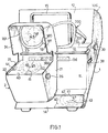
- an apparatus 100 comprising a frame 1 with a front face 11, a base surface 13 intended to receive a spectacle frame 200, and a rear cover 12, the internal part of which forms a reflective screen.
- a support frame 15 is mounted on the base surface 13 and makes it possible to retain the frame 200, which rests on the base surface 13, in a plane substantially parallel to the plane of the frame 15.
- a graduated measurement scale 36 is affixed to the front face 11 of the frame 1, below the base plane 13.
- the measurement scale 36 which is parallel both to the base plane 13 and to the reference plane determined by the frame 15 is symmetrical with respect to an origin 360 which determines the axis of the device.
- Centering means 18 are arranged above the base surface 13 and are intended to hold the middle part of the frame 200 on an axis passing through the origin 360 and perpendicular to the measurement scale 36.
- the means of centering 18 may for example include a head 180 which is placed between the two circles 201, 202 of the frame 200, under the connecting bridge 203, in order to prevent any play in the lateral direction for the frame 200.
- the means of centering 18 are adjustable in height and the position of the head 180, mounted on the rod 181, can be controlled by the lever 38, in order to adapt to the different shapes and sizes of the frame and fix the axial position of the frame 200 without prevent the two circles 201, 202 of the frame from resting on the base surface 13.
- a lamp 17 (fig. 2) is advantageously placed in the frame 1 in order to illuminate the internal reflecting surface of the cover 12, and consequently illuminate the reference surface formed by the plane of the frame 200 parallel to the frame 15.
- a cover opaque 19 can be operated using the button 39 to adjust the amount of light sent to the reflective screen of the cover 12.
- the intensity of the light emitted by the lamp 17 can still be adjusted directly by acting on the 'power supply, using a rheostat for example.
- a carriage 2 is mounted on the front part of the device, in front of the front face 11, the base surface 13 and the mount 200.
- the carriage 2 can slide on a guide 16 parallel to the front face 11 of the frame 1 and at the measurement scale 36.
- the carriage 2 comprises a lower body 21 having an upper receiving surface 22, and an upper awning 24 having two lateral branches between which a semi-reflecting mirror 25 is inserted.
- the carriage 2 is open on its faces front and rear at the level of the upper canopy 24 to allow viewing through the reflecting mirror 25, as well as in a central part to reveal the measurement scale 36 in front of which the carriage 2 can circulate.
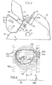
- the mirror 25 is located in the bisector plane of the dihedron constituted on the one hand by the reference plane of the frame 15 on which a frame 200 rests and on the other hand, by the receiving surface 22 located on the top of the lower body 21 of the carriage 2.
- the angle between the mirror 25 and the reference plane of the frame 15, or the receiving surface 22 is approximately 45 °.
- the receiving surface 22 is preferably constituted by a transparent plate, for example made of glass or plastic and is intended to receive a removable plate, such as 40 which is also preferably transparent and is made for example of plastic.
- a plate such as 40 comprises a longitudinal axis 41 and various lines 42 representing the contours of standard rough glasses of different diameters.
- the image of the plate 40 is reflected by the semi-transparent mirror 25 and is superimposed on the spectacle frame 200 to form, for an observer placed in front of the mirror 25, virtual lines 141, 142 identical to lines 41, 42.
- a lamp 23 disposed inside the lower body 21 can illuminate a plate 40 and facilitate observation through the semi mirror -transparent 25 which on the one hand returns to the observer the image of the plate 40 and on the other hand reveals the frame 200.
- the balance between the lighting of the frame and the plate 40 is easily produced using the operating button 39 acting on the lamp 17.
- the receiving surface 22 of the carriage body 21 is advantageously itself provided with lines 44 forming a measurement scale, which are superimposed on the lines or marks formed on the plates 40.
- the lines 44 superimposed on the surface receiver 22 can be moved in the plane of said surface, using the adjustment knob 26, in particular in a direction perpendicular to the direction of movement of the sliding carriage. This increases the convenience of the measurements.
- the lower part 14 of the apparatus 100 can serve as a storage drawer for the plates 40 which are not used.
- the frame chosen is first placed on the head 180 of the centering means 18 and leaned against the frame 15 parallel to the latter.
- the frame is then lowered on the base surface 13 until the two circles 201, 201 rest well on the surface 13.
- the frame is thus perfectly centered relative to the axis passing through the origin 360 of the fixed measurement scale 36.
- a plate 40 is then placed on the receiving surface 22 of the carriage 2 carrying lines and marks corresponding to the type of lens which must be installed on the spectacle frame.
- Each plate 40 is rectangular and planar and comprises, in addition to a longitudinal axis 41, a mark 46 corresponding to the optical center and various circles 42 corresponding to standard glass diameters, for example 50, 60, 65, 70, 75 mm. Each plate 40 further carries, inside the circles, marks which depend on the type of glass.
- These additional references 43, 45, 47 do not exist in the case of single-vision lenses, but are necessary in the case of multifocal or progressive lenses and make it possible to correctly position a circle corresponding to a fictitious lens, relative to the spectacle frame. , taking into account the positions previously identified by the pupil of the user with respect to this frame.
- a diameter of bifocal lens to be mounted on the right circle 201 of a spectacle frame 200 (FIG. 3).
- a plate 40 corresponding to the bifocal glasses is then placed on the receiving surface 22 of the carriage 2.
- the spectacle frame is arranged, as indicated above, against the frame 15, and its central bridge 203 rests on the centering head 180 which is lowered until the lower parts of the circles of the frame rest firmly on the surface 13.
- the carriage 2 is then moved in front of the graduated scale 36 of the front face 11 of the device.
- the measurement scale 36 is visible below the semi-transparent mirror 25 and, preferably, appears through the carriage 2 immediately above the receiving surface 22 of the lower body 21.
- the carriage can then be positioned easily so that, on the measurement scale 36, the distance between the origin 360 and the reference located opposite the longitudinal axis 41 of the plate 40, corresponds to the pupillary half-distance e of the user.
- the relative positions of the frame and the plate 40 are then well defined in the lateral direction and the real and virtual images of the circle 201 and of the plate 40 are superimposed behind the screen formed by the mirror 25.
- the only remaining operation consists in comparing the frame circle 201 and the circles 142 representative of lenses to determine the circle of smallest diameter making it possible to cover the entire surface of the frame circle 201.
- the height positioning of the glasses is not indifferent.
- the measurement operations carried out on a right circle 201 of the frame can be carried out in the same way on the left circle 202. It suffices to move the carriage 2 to the other side of the central marker 360 and to install on the receiving surface 22 a plate 40 corresponding to left glasses, in the case where the type of glass whose diameter is to be determined is not unifocal.
- the apparatus according to the invention can be used to determine the diameter of very different types of glasses, without having these glasses beforehand, but simply inexpensive plates, for example, made of easy-to-make plastic material. ser, since it suffices that they bear a limited number of marks characteristic of the type of glass to be chosen.
- the manipulations aimed at superimposing the image 140 of a plate 40 on a frame 200 are particularly simple since, as soon as the frame is placed on the device, it suffices to move in two perpendicular directions, by simple sliding along guides 16 and 27 respectively the carriage 2 with respect to the base 1 of the apparatus and the plate 40 with respect to the carriage 2.
- the semi-transparent mirror 25 be situated substantially in a vertical plane, or slightly inclined relative to the vertical, and that the base surface 13 as well as the receiving surface 22 are inclined by so that their front part is raised and that a spectacle frame 200 and a plate 40 can easily come into abutment respectively against the support frame 15 and against the bottom of the carriage 2 or the front face 11 of the base 1.
Description
La présente invention a pour objet un appareil pour la détermination du diamètre de verres correcteurs adaptables à une monture de lunettes.The present invention relates to an apparatus for determining the diameter of corrective lenses adaptable to a spectacle frame.
Les verres correcteurs de lunettes fabriqués présentent, en général, un contour circulaire et les opticiens doivent ensuite adapter chaque verre à la forme de monture choisie par leurs clients. Un problème particulier nait du fait que lorsqu'un client a choisi un type de monture, l'opticien ne dispose pas encore des verres correcteurs bruts qu'il doit d'abord commander chez le fabricant pour ensuite les tailler et les adapter à la monture choisie. Pour des raisons d'économie évidentes, il convient de choisir, parmi les divers calibres de verres correcteurs d'un type donné, le verre correcteur dont le diamètre est le plus faible possible mais qui permet de remplir complètement le cercle de la monture choisie, dont la forme est en général essentiellement non circulaire, tout en assurant un montage optiquement correct. Le choix et le positionnement d'un verre correcteur dépend ainsi de la monture choisie et doivent également prendre en compte des facteurs liés à l'usager, comme par exemple la valeur du demi-écart pupillaire, qui est variable selon les individus. Il s'est avéré particulièrement difficile de déterminer de façon aisée, en présence d'un usager et d'une monture de lunette déterminés, le diamètre d'un verre correcteur de type choisi, alors même que les différents calibres de verres existants ne sont pas à la disposition du praticien pour autoriser des essais des différents calibres susceptibles de convenir.The corrective lenses for glasses produced generally have a circular outline and opticians must then adapt each lens to the shape of frame chosen by their customers. A particular problem arises from the fact that when a customer has chosen a type of frame, the optician does not yet have raw corrective lenses which he must first order from the manufacturer and then cut and adapt them to the frame. chosen. For obvious reasons of economy, it is necessary to choose, among the various calibers of corrective lenses of a given type, the corrective lens whose diameter is as small as possible but which makes it possible to completely fill the circle of the frame chosen, whose shape is generally essentially non-circular, while ensuring optically correct mounting. The choice and positioning of a corrective lens thus depends on the frame chosen and must also take into account factors related to the user, such as for example the value of the pupillary half-distance, which is variable depending on the individual. It has proven to be particularly difficult to easily determine, in the presence of a user and a fixed spectacle frame, the diameter of a corrective lens of the chosen type, even though the different sizes of existing lenses are not not available to the practitioner to authorize tests of different sizes that may be suitable.
On a déjà proposé divers procédés et dispositifs susceptibles de permettre la détermination du diamètre utile des verres de lunettes à adapter à une monture choisie, en fonction d'un usager déterminé. Ainsi, selon un premier système connu, un dispositif de mesure comprenant des éléments mobiles et un cadre guide dont la forme est comparable à celle d'une monture de lunettes est fixé sur la monture elle-même et s'utilise sur le patient. Des éléments du dispositif de mesure sont mobiles verticalement et horizontalement pour superposer un repère à la pupille du patient et des repères en arcs de cercle permettent de déterminer le diamètre de verre utile. Un tel système présente toutefois des inconvénients car il est relativement fragile et implique de réaliser un nombre d'opérations assez longues sur le patient lui-même, ce qui est relativement peu commode. Par ailleurs, la fixation du cadre guide du dispositif de mesure sur la monture de lunettes elle-même n'est pas adaptée aux montures sans drageoir. Ce dispositif de mesure connu, qui est adapté aux verres progressifs, n'est pas utilisable pour les verres à double ou triple foyer et entraine des manipulations trop longues lorsqu'il s'agit de choisir des verres unifocaux.Various methods and devices have already been proposed capable of allowing the useful diameter of the spectacle lenses to be determined to be adapted to a chosen frame to be determined, as a function of a determined user. Thus, according to a first known system, a measuring device comprising movable elements and a guide frame whose shape is comparable to that of a spectacle frame is fixed to the frame itself and is used on the patient. Elements of the measuring device are movable vertically and horizontally to superimpose a mark on the pupil of the patient and marks in arcs of a circle make it possible to determine the useful glass diameter. However, such a system has drawbacks because it is relatively fragile and involves carrying out a number of fairly long operations on the patient himself, which is relatively inconvenient. Furthermore, the fixing of the guide frame of the measuring device to the spectacle frame itself is not suitable for frames without a bezel. This known measuring device, which is suitable for progressive lenses, cannot be used for bifocals or triple focal lengths and involves too long manipulations when it comes to choosing single vision lenses.
Il est également connu d'utiliser un jeu de disques circulaires tronqués, en matière plastique transparente, munis de repères et prévus pour correspondre à différents diamètres de verres correcteurs bruts standards. Les disques circulaires tronqués sont superposés successivement à la monture de lunettes choisie, tandis que cette dernière est elle-même portée par l'utilisateur. Le système est également assez peu commode car il implique de faire des superpositions successives de disques et d'une monture de lunettes alors que cette dernière est elle-même portée par un usager, ce qui reste assez incommode.It is also known to use a set of truncated circular discs, made of transparent plastic, provided with marks and designed to correspond to different diameters of standard raw corrective lenses. The truncated circular discs are successively superimposed on the chosen spectacle frame, while the latter is itself worn by the user. The system is also quite inconvenient because it involves making successive overlays of discs and of a spectacle frame while the latter is itself carried by a user, which remains quite inconvenient.
La présente invention a précisément pour objet de remédier aux inconvénients précités et de permettre de déterminer de façon simple et rapide le diamètre de verres approprié à une monture de lunettes et à un individu en occasionnant un minimum de gêne pour l'usager.The object of the present invention is precisely to remedy the aforementioned drawbacks and to make it possible to quickly and easily determine the diameter of lenses suitable for a spectacle frame and for an individual while causing a minimum of discomfort for the user.
L'invention a encore pour objet de proposer un appareil de mesure qui soit utilisable pour déterminer le diamètre d'une grande variété de type de verres différents, notamment des verres unifocaux, bifocaux, progressifs.The object of the invention is also to propose a measuring device which can be used to determine the diameter of a wide variety of types of different lenses, in particular single-vision, two-vision and progressive lenses.
Ces buts sont atteints grâce à un appareil du type mentionné au début qui, conformément à l'invention, comprend au moins un socle muni a) d'une échelle de mesure linéaire symétrique, b) de moyens de guidage parallèles à ladite échelle de mesure, et c) d'une surface de base, d'un support d'appui et de moyens de centrage pour maintenir une monture de lunettes dans une position prédéterminée dans un plan de référence parallèle à ladite échelle de mesure et de façon symétrique par rapport à un plan perpendiculaire audit plan de référence et passant par l'axe médian de ladite échelle de mesure symétrique, et comprenant en outre au moins un chariot coulissant sur lesdits moyens de guidage devant ladite échelle de mesure et ledit plan de référence, ledit chariot comprenant une première partie munie d'une surface réceptrice plane parallèle à ladite échelle de mesure, faisant un angle par rapport audit plan de référence, et adaptée pour recevoir des plaques amovibles munies de repères et lignes figurant au moins le contour d'un ou de plusieurs types de verres correcteurs bruts, et une deuxième partie équipée d'un miroir semi-réfléchissant placé dans le plan bissecteur du dièdre déterminé par ladite surface réceptrice et ledit plan de référence.These aims are achieved by an apparatus of the type mentioned at the start which, according to the invention, comprises at least one base provided with a) a symmetrical linear measurement scale, b) guide means parallel to said measurement scale , and c) a base surface, a support support and centering means for maintaining a spectacle frame in a predetermined position in a reference plane parallel to said measurement scale and symmetrically with respect to to a plane perpendicular to said reference plane and passing through the median axis of said symmetrical measurement scale, and further comprising at least one carriage sliding on said guide means in front of said measurement scale and said reference plane, said carriage comprising a first part provided with a flat receiving surface parallel to said measurement scale, making an angle with respect to said reference plane, and adapted to receive removable plates provided with marks and lines appearing at least the outline of one or more types of raw corrective lenses, and a second part equipped with a semi-reflecting mirror placed in the bisector plane of the dihedron determined by said receiving surface and said reference plane.
Selon un exemple particulier de réalisation, le miroir semi-réfléchissant est incliné d'environ 45° par rapport d'une part au plan de référence et d'autre part à la surface réceptrice.According to a particular embodiment, the semi-reflecting mirror is inclined by about 45 ° relative on the one hand to the reference plane and on the other hand to the receiving surface.
De préférence, la surface de base de réception de la monture de lunettes est sensiblement parallèle à ladite surface réceptrice du chariot.Preferably, the base receiving surface of the spectacle frame is substantially parallel to said receiving surface of the carriage.
Le support d'appui de la monture de lunettes comprend un cadre qui est fixé sur la surface de base et définit ledit plan de référence.The support for supporting the spectacle frame comprises a frame which is fixed to the base surface and defines said reference plane.
Les moyens de centrage pour maintenir la monture de lunettes de façon symétrique par rapport à un plan perpendiculaire au plan de référence et passant par l'axe médian de l'échelle de mesure comprennent un support réglable déplaçable parallèlement au plan de référence.The centering means for holding the spectacle frame symmetrically with respect to a plane perpendicular to the reference plane and passing through the median axis of the measurement scale comprise an adjustable support movable parallel to the reference plane.
Selon une caractéristique de la présente invention, les plaques amovibles sont réalisées en matière plastique transparente.According to a characteristic of the present invention, the removable plates are made of transparent plastic.
Une échelle de mesure est formée sur la surface réceptrice des plaques amovibles.A measuring scale is formed on the receiving surface of the removable plates.
Dans ce cas, il est avantageux que l'échelle de mesure formée sur la surface réceptrice des plaques amovibles puisse être déplacée dans son plan dans un sens perpendiculaire au sens de déplacement du chariot coulissant.In this case, it is advantageous that the measuring scale formed on the receiving surface of the removable plates can be moved in its plane in a direction perpendicular to the direction of movement of the sliding carriage.
Afin de faciliter la visualisation, une source lumineuse est disposée dans le chariot coulissant, sous la surface réceptrice des plaques qui est elle-même transparente.In order to facilitate viewing, a light source is placed in the sliding carriage, under the plate receiving surface which is itself transparent.
Une source lumineuse est disposée dans le socle et coopère avec une surface réfléchissante pour éclairer ledit plan de référence.A light source is arranged in the base and cooperates with a reflective surface to illuminate said reference plane.
On peut en outre prévoir des moyens de réglage de l'intensité de la lumière envoyée dans ledit plan de référence par la source lumineuse disposée dans le socle.It is also possible to provide means for adjusting the intensity of the light sent into said reference plane by the light source disposed in the base.
L'appareil selon l'invention permet ainsi d'effectuer des mesures précises de façon commode, du fait que la monture de lunettes est toujours disposée sur un support stable et que la combinaison de moyens mise en oeuvre assure une visualisation totale de tous les facteurs à prendre en compte pour la détermination du diamètre adéquat d'un type de verre en fonction d'une monture de lunettes déterminée.The apparatus according to the invention thus makes it possible to carry out precise measurements in a convenient manner, owing to the fact that the spectacle frame is always placed on a stable support and that the combination of means used ensures total visualization of all the factors to be taken into account for the determination of the adequate diameter of a type of lens according to a determined spectacle frame.
D'autres caractéristiques et avantages de l'invention apparaitront mieux à la lecture de la description qui fait suite d'un mode particulier de réalisation de l'invention, en référence aux dessins annexés, sur lesquels:
- - la fig. 1 est une vue en perspective d'un appareil conforme à l'invention,
- - la fig. 2 est une vue de côté de l'appareil de la fig. 1, et
- - la fig. 3 est une vue de détail montrant la superposition des images visualisées à travers le
chariot 2 de l'appareil de la fig. 1.
- - fig. 1 is a perspective view of an apparatus according to the invention,
- - fig. 2 is a side view of the apparatus of FIG. 1, and
- - fig. 3 is a detail view showing the superimposition of the images viewed through the
carriage 2 of the apparatus of FIG. 1.
On voit sur la fig. 1 un appareil 100 comprenant un bâti 1 avec une face avant 11, une surface de base 13 destinée à recevoir une monture de lunettes 200, et un capot arrière 12 dont la partie interne forme un écran réflecteur. Un cadre d'appui 15 est monté sur la surface de base 13 et permet de retenir la monture 200, qui repose sur la surface de base 13, dans un plan sensiblement parallèle au plan du cadre 15.We see in fig. 1 an
Une échelle de mesure graduée 36 est apposée sur la face frontale 11 du bâti 1, en dessous du plan de base 13. L'échelle de mesure 36, qui est parallèle à la fois au plan de base 13 et au plan de référence déterminé par le cadre 15, est symétrique par rapport à une origine 360 qui détermine l'axe de l'appareil. Des moyens de centrage 18 sont disposés au-dessus de la surface de base 13 et sont destinés à maintenir la partie médiane de la monture 200 sur un axe passant par l'origine 360 et perpendiculaire à l'échelle de mesure 36. Les moyens de centrage 18 peuvent comprendre par exemple une tête 180 qui vient se placer entre les deux cercles 201, 202 de la monture 200, sous le pont de liaison 203, afin d'empêcher tout jeu dans le sens latéral pour la monture 200. Les moyens de centrage 18 sont réglables en hauteur et la position de la tête 180, montée sur la tige 181, peut être commandée par la manette 38, afin de s'adapter aux différentes formes et tailles de monture et fixer la position axiale de la monture 200 sans empêcher que les deux cercles 201, 202 de la monture reposent sur la surface de base 13.A graduated
Une lampe 17 (fig. 2) est avantageusement disposée dans le bâti 1 afin d'éclairer la surface réfléchissante interne du capot 12, et par suite éclairer la surface de référence constituée par le plan de la monture 200 parallèle au cadre 15. Un capot opaque 19 peut être manoeuvré à l'aide du bouton 39 pour régler la quantité de lumière envoyée sur l'écran réflecteur du capot 12. Naturellement, l'intensité de la lumière émise par la lampe 17 peut encore être réglée directement en agissant sur l'alimentation électrique, à l'aide d'un rhéostat par exemple.A lamp 17 (fig. 2) is advantageously placed in the frame 1 in order to illuminate the internal reflecting surface of the
Un chariot 2 est monté sur la partie avant de l'appareil, devant la face frontale 11, la surface de base 13 et la monture 200. Le chariot 2 peut coulisser sur un guide 16 parallèlement à la face avant 11 du bâti 1 et à l'échelle de mesure 36. Le chariot 2 comporte un corps inférieur 21 présentant une surface réceptrice supérieure 22, et un auvent supérieur 24 présentant deux branches latérales entre lesquelles est inséré un miroir semi-réfléchissant 25. Le chariot 2 est ouvert sur ses faces avant et arrière au niveau de l'auvent supérieur 24 pour permettre une visualisation à travers le miroir réfléchissant 25, ainsi que dans une partie médiane pour laisser apparaitre l'échelle de mesure 36 devant laquelle peut circuler le chariot 2.A
Le miroir 25 est situé dans le plan bissecteur du dièdre constitué d'une part par le plan de référence du cadre 15 sur lequel s'appuie une monture 200 et d'autre part, par la surface réceptrice 22 située sur le dessus du corps inférieur 21 du chariot 2. Selon un exemple avantageux, l'angle entre le miroir 25 et le plan de référence du cadre 15, ou la surface réceptrice 22 est d'environ 45°.The
La surface réceptrice 22 est de préférence constituée par une plaque transparente, par exemple en verre ou en matière plastique et est destinée à recevoir une plaque amovible, telle que 40 qui est également de préférence transparente et est réalisée par exemple en matière plastique. Une plaque telle que 40 comprend un axe longitudinal 41 et diverses lignes 42 figurant les contours de verres bruts standards de différents diamètres. L'image de la plaque 40 est réfléchie par le miroir semi-transparent 25 et se superpose à la monture de lunettes 200 pour former, pour un observateur placé devant le miroir 25 des lignes virtuelles 141, 142 identiques aux lignes 41, 42. Dans le cas où la surface réceptrice 22 du corps inférieur 21 du chariot 2 et les plaques 40 sont toutes deux transparentes, une lampe 23 disposée à l'intérieur du corps inférieur 21 peut éclairer une plaque 40 et faciliter l'observation à travers le miroir semi-transparent 25 qui d'une part renvoie à l'observateur l'image de la plaque 40 et d'autre part laisse apparaitre la monture 200. L'équilibre entre l'éclairage de la monture et de la plaque 40 est aisément réalisé a l'aide du bouton de manoeuvre 39 agissant sur la lampe 17.The
La surface réceptrice 22 du corps de chariot 21 est avantageusement elle-même munie de lignes 44 formant échelle de mesure, qui se superposent aux lignes ou repères formés sur les plaques 40. Selon un mode de réalisation particulier, les lignes 44 superposées à la surface réceptrice 22 peuvent être déplacées dans le plan de ladite surface, à l'aide du bouton de réglage 26, notamment dans un sens perpendiculaire au sens de déplacement du chariot coulissant. Ceci accroit la commodité des mesures.The
Comme on peut le voir sur la fig. 1, la partie inférieure 14 de l'appareil 100 peut servir de tiroir de rangement pour les plaques 40 non utilisées.As can be seen in fig. 1, the
Le fonctionnement et l'utilisation de l'appareil de mesure selon l'invention seront maintenant expliqués de façon détaillée en référence aux figs 1 et 3.The operation and use of the measuring device according to the invention will now be explained in detail with reference to FIGS. 1 and 3.
On considère d'abord que, de façon classique, on a mesuré sur l'usager la valeur de son demi-écart pupillaire ainsi que, dans le cas où il s'agit d'installer des verres multifocaux ou progressifs, la distance entre la pupille et le rebord intérieur de la partie inférieure du cercle de la monture choisie. JI reste alors, sur la base de ces données, et compte tenu de la puissance de verre choisie, et du type de verres, à déterminer le diamètre de verre brut adapté pour être monté dans les cercles de la monture choisie. L'appareil selon l'invention permet de procéder à cette détermination avec la monture choisie, sans que des opérations d'essai ou de mesure supplémentaires aient à être effectuées sur l'usager, ou sur la monture portée par l'usager.We first consider that, in a conventional manner, the value of its pupillary half-distance has been measured on the user as well as, in the case where it is a question of installing multifocal or progressive lenses, the distance between the pupil and the inner rim of the lower part of the circle of the chosen frame. JI then remains, on the basis of these data, and taking into account the power of lens chosen, and the type of lenses, to determine the diameter of raw lens suitable for being mounted in the circles of the frame chosen. The apparatus according to the invention makes it possible to make this determination with the frame chosen, without additional test or measurement operations having to be carried out on the user, or on the frame worn by the user.
La monture choisie est d'abord posée sur la tête 180 des moyens de centrage 18 et adossée contre le cadre 15 parallèlement à celui-ci. La monture est alors abaissée sur la surface de base 13 jusqu'à ce que les deux cercles 201, 201 reposent bien d'aplomb sur la surface 13. La monture est ainsi parfaitement centrée par rapport à l'axe passant par l'origine 360 de l'échelle de mesure fixe 36. On place alors sur la surface réceptrice 22 du chariot 2 une plaque 40 portant des lignes et repères correspondant au type de verre qui doit être installé sur la monture de lunettes.The frame chosen is first placed on the
Chaque plaque 40 est rectangulaire et plane et comprend, outre un axe longitudinal 41, une repère 46 correspondant au centre optique et divers cercles 42 correspondant à des diamètres de verres standards, par exemple 50, 60, 65, 70, 75 mm. Chaque plaque 40 porte en outre, à l'intérieur des cercles, des repères qui dépendent du type de verre. Ces repères supplémentaires 43, 45, 47 n'existent pas dans le cas de verres unifocaux, mais sont nécessaires dans le cas de verres multifocaux ou progressifs et permettent de positionner correctement un cercle correspondant à un verre fictif, par rapport à la monture de lunettes, en tenant compte des positions repérées au préalable de la pupille de l'usager par rapport à cette monture.Each
On considérera à titre d'exemple la détermination d'un diamètre de verre à double foyer à monter sur le cercle droit 201 d'une monture de lunettes 200 (fig. 3). Une plaque 40 correspondant aux verres à double foyer est alors disposée sur la surface réceptrice 22 du chariot 2. La monture de lunettes est disposée, comme indiqué plus haut, contre le cadre 15, et son pont central 203 repose sur la tête de centrage 180 qui est abaissée jusqu'à ce que les parties inférieures des cercles de la monture reposent bien d'aplomb sur la surface 13. Le chariot 2 est alors déplacé devant l'échelle graduée 36 de la face avant 11 de l'appareil. L'échelle de mesure 36 est visible en dessous du miroir semi-transparent 25 et, de façon préférentielle, apparait à travers le chariot 2 immédiatement au dessus de la surface réceptrice 22 du corps inférieur 21. Le chariot peut alors être positionné aisément de manière que, sur l'échelle de mesure 36, la distance entre l'origine 360 et le repère situé en face de l'axe longitudinal 41 de la plaque 40, corresponde au demi-écart pupillaire e de l'usager. Les positions relatives de la monture et de la plaque 40 sont alors bien définies dans le sens latéral et les images réelle et virtuelle du cercle 201 et de la plaque 40 se superposent derrière l'écran constitué par le miroir 25. Dans le cas de verres unifocaux, la seule opération restant à effectuer consiste à comparer le cercle de monture 201 et les cercles 142 représentatifs de verres pour déterminer le cercle de plus petit diamètre permettant de couvrir toute la surface du cercle de monture 201. Dans le cas de verres à double foyer, le positionnement en hauteur des verres n'est pas indifférent. C'est pourquoi il convient d'abord d'amener, à l'aide du bouton de réglage 26, l'image 144 d'une graduation de référence de l'échelle de mesure 44 de la surface réceptrice 22, au niveau du rebord interne 210 de la partie inférieure du cercle 201 de la monture 200. La position de la pupille par rapport au rebord inférieur 210 peut alors être aisément situé, grâce aux lignes 144, et un glissement de la plaque 40 sur la surface réceptrice 22 permet de déplacer l'image 140 de la plaque 40 par rapport aux lignes repères 144 et à la monture 200 afin de positionner correctement les repères 143, 145. Il suffit alors, comme dans le cas précédent de verres unifocaux, de repérer le cercle 142 de diamètre juste suffisant pour couvrir toute la surface interne du cercle de monture 201.As an example, consider the determination of a diameter of bifocal lens to be mounted on the
Les opérations de mesure effectuées sur un cercle droit 201 de monture peuvent être réalisées de la même manière sur le cercle gauche 202. Il suffit de déplacer le chariot 2 de l'autre côté du repère central 360 et d'installer sur la surface réceptrice 22 une plaque 40 correspondant à des verres gauche, dans le cas où le type de verre dont le diamètre est à déterminer n'est pas uni- focal.The measurement operations carried out on a
L'appareil selon l'invention peut être utilisé pour déterminer le diamètre de types de verres très divers, sans disposer de ces verres au préalable, mais simplement de plaques bon marché, par exemple, en matière plastique faciles à réaliser, puisqu'il suffit qu'elles portent un nombre limité de repères caractéristiques du type de verre à choisir.The apparatus according to the invention can be used to determine the diameter of very different types of glasses, without having these glasses beforehand, but simply inexpensive plates, for example, made of easy-to-make plastic material. ser, since it suffices that they bear a limited number of marks characteristic of the type of glass to be chosen.
Les manipulations visant à superposer l'image 140 d'une plaque 40 sur une monture 200 sont particulièrement simples puisque, dès lors que la monture est placée sur l'appareil, il suffit de déplacer selon deux directions perpendiculaires, par simple coulissement le long de guides 16 et 27 respectivement le chariot 2 par rapport au socle 1 de l'appareil et la plaque 40 par rapport au chariot 2. En particulier, dans le cas de verres unifocaux, il suffit d'abord de positionner le chariot 2 pour que l'axe longitudinal 41 d'une plaque 40 soit à une distance convenable e de l'origine 360, puis de faire glisser progressivement la plaque 40 entre les rebords guides 27 du corps inférieur 21 du chariot 2, qui sont parallèles audit axe 41 pour déterminer sur le miroir 25 le plus petit cercle 142 capable d'inclure entièrement le cercle de monture 201.The manipulations aimed at superimposing the
Il est préférable, pour la commodité des manipulations, que le miroir semi-transparent 25 soit situé sensiblement dans un plan vertical, ou peu incliné par rapport à la verticale, et que la surface de base 13 ainsi que la surface réceptrice 22 soient inclinées de sorte que leur partie avant est surélevée et qu'une monture de lunette 200 et une plaque 40 puissent venir facilement en butée respectivement contre le cadre d'appui 15 et contre le fond du chariot 2 ou la face avant 11 du socle 1.It is preferable, for convenience of handling, that the
Claims (13)
Applications Claiming Priority (2)
| Application Number | Priority Date | Filing Date | Title |
|---|---|---|---|
| FR7915702A FR2459494A1 (en) | 1979-06-19 | 1979-06-19 | APPARATUS FOR DETERMINING THE DIAMETER OF PRESCRIPTION GLASSES |
| FR7915702 | 1979-09-19 |
Publications (2)
| Publication Number | Publication Date |
|---|---|
| EP0021998A1 EP0021998A1 (en) | 1981-01-07 |
| EP0021998B1 true EP0021998B1 (en) | 1984-05-30 |
Family
ID=9226803
Family Applications (1)
| Application Number | Title | Priority Date | Filing Date |
|---|---|---|---|
| EP80400903A Expired EP0021998B1 (en) | 1979-06-19 | 1980-06-19 | Apparatus to determine the diameter of spectacle glasses |
Country Status (4)
| Country | Link |
|---|---|
| US (1) | US4309826A (en) |
| EP (1) | EP0021998B1 (en) |
| DE (1) | DE3068015D1 (en) |
| FR (1) | FR2459494A1 (en) |
Cited By (1)
| Publication number | Priority date | Publication date | Assignee | Title |
|---|---|---|---|---|
| DE3606233A1 (en) * | 1985-03-08 | 1986-09-11 | Essilor International (Compagnie Générale d'Optique), Créteil, Val-de-Marne | DEVICE FOR DETERMINING THE DIAMETER OF UNPROCESSED OPHTHALMIC LENSES TO BE INSERTED IN A PARTICULAR EYE FRAME AND / OR FOR CHECKING THE CORRESPONDING ASSEMBLY |
Families Citing this family (5)
| Publication number | Priority date | Publication date | Assignee | Title |
|---|---|---|---|---|
| JPS5955411A (en) * | 1982-09-24 | 1984-03-30 | Hoya Corp | Determination method of optimum thickness for spectacle lens |
| US4817024A (en) * | 1984-03-02 | 1989-03-28 | Hoya Corporation | Spectacle-frame shape data producing method |
| DE3447119A1 (en) * | 1984-12-22 | 1986-06-26 | 4803 Steinhagen Wehmeier Reinhard | DEMONSTRATION DEVICE FOR ILLUSTRATING THE REQUIRED GLASS SIZE FOR EYEWEAR |
| JP2770540B2 (en) * | 1990-03-09 | 1998-07-02 | 株式会社ニコン | Lens shape measuring device and grinding device having the same |
| DE9203381U1 (en) * | 1992-03-13 | 1992-08-06 | Scheibner, Andreas, 3044 Neuenkirchen, De |
Family Cites Families (11)
| Publication number | Priority date | Publication date | Assignee | Title |
|---|---|---|---|---|
| AT232293B (en) * | 1962-07-25 | 1964-03-10 | Oskar Vogel | Pupil measurement adjustment device |
| FR1493482A (en) * | 1966-05-14 | 1967-09-01 | Lunetiers Cottet Poichet Soc D | Device for placing spectacle lenses on the grinding machine according to the pupillary distance of the wearer and the center distance of the arches of the frame |
| FR1491018A (en) * | 1966-08-31 | 1967-08-04 | Improvements to universal precision direct copy devices to reproduce the contour of the lens corrected according to the optical data from the spectacle frame | |
| FR1604128A (en) * | 1967-05-10 | 1971-07-12 | ||
| FR1604198A (en) * | 1968-12-30 | 1971-07-26 | ||
| FR2037340A5 (en) * | 1970-02-02 | 1970-12-31 | Netter Roger | |
| US3804528A (en) * | 1972-06-05 | 1974-04-16 | Gemco Mfg Co | Print projector for fitting contact lenses |
| US4099881A (en) * | 1975-09-19 | 1978-07-11 | Transidyne General Corporation | Viewer for biological diffusion plate |
| FR2362418A1 (en) * | 1976-08-20 | 1978-03-17 | Essilor Int | Measuring and checking of spectacle lenses in frame - uses diagram of calibrated lines mounted underneath and centred w.r.t. frame |
| US4098002A (en) * | 1977-06-13 | 1978-07-04 | Humphrey Instruments Incorporated | Apparatus for locating inter-pupilary of nose bridge mounted spectacles to lens meter |
| US4196978A (en) * | 1977-10-19 | 1980-04-08 | Johnson D Olin | Biofocal type ophthalmic lens alignment determining device |
-
1979
- 1979-06-19 FR FR7915702A patent/FR2459494A1/en active Granted
-
1980
- 1980-06-16 US US06/159,619 patent/US4309826A/en not_active Expired - Lifetime
- 1980-06-19 EP EP80400903A patent/EP0021998B1/en not_active Expired
- 1980-06-19 DE DE8080400903T patent/DE3068015D1/en not_active Expired
Cited By (1)
| Publication number | Priority date | Publication date | Assignee | Title |
|---|---|---|---|---|
| DE3606233A1 (en) * | 1985-03-08 | 1986-09-11 | Essilor International (Compagnie Générale d'Optique), Créteil, Val-de-Marne | DEVICE FOR DETERMINING THE DIAMETER OF UNPROCESSED OPHTHALMIC LENSES TO BE INSERTED IN A PARTICULAR EYE FRAME AND / OR FOR CHECKING THE CORRESPONDING ASSEMBLY |
Also Published As
| Publication number | Publication date |
|---|---|
| FR2459494B1 (en) | 1983-03-18 |
| EP0021998A1 (en) | 1981-01-07 |
| DE3068015D1 (en) | 1984-07-05 |
| US4309826A (en) | 1982-01-12 |
| FR2459494A1 (en) | 1981-01-09 |
Similar Documents
| Publication | Publication Date | Title |
|---|---|---|
| CA2811410C (en) | Method for selecting progressive ophthalmic lenses | |
| EP1817562B1 (en) | Device for automatically measuring characteristics of an ophthalmic lens | |
| EP3082567B1 (en) | Device and method for measuring subjective refraction | |
| WO2006061474A1 (en) | Device for automatic mounting preparation of ophthalmic lenses enabling several lenses to be processed at the same time | |
| FR2915289A1 (en) | DEVICE AND METHOD FOR PREPARING AN OPHTHALMIC LENS FOR MACHINING | |
| EP0021998B1 (en) | Apparatus to determine the diameter of spectacle glasses | |
| FR2910644A1 (en) | Extraction opening position and/or transversal dimension determining device for ophthalmic lens of spectacles, has processing system determining position or transversal dimension of opening corresponding to required transversal dimension | |
| FR2663528A3 (en) | Method for taking the necessary measurements for fitting corrective glasses, and means for carrying out this method | |
| EP2851739B1 (en) | Method for acquiring and measuring geometric data of a demonstration lens adapted to a spectacle frame | |
| EP2196845A1 (en) | Method for preparing an ophthalmic lens in order to mount it on a curved spectacle frame | |
| FR2931002A1 (en) | Ophthalmic parameters measuring assembly for e.g. preparing ophthalmic lens, has support adjusted to normal reading distance such that processing unit simultaneously determines normal distance and distance between patient pupils | |
| FR2462724A1 (en) | DEVICE FOR THE DECENTRING OF GLASSES OF GOGGLES AND THE PLACEMENT OF A RETENTION MEMBER | |
| EP3074178B1 (en) | Method for bevelling an ophthalmic lens | |
| CA2692840C (en) | Method and device for measuring the curve of a spectacle frame | |
| FR2690833A1 (en) | Measuring device for taking pictures to adapt glasses to a patient. | |
| FR2829842A1 (en) | Device for acquisition of the necessary parameters for optimum positioning of ophthalmic lenses in spectacle frames is based on measurement of reflections on the cornea and marking of reference points on spectacle frames | |
| WO2006061475A1 (en) | Method for locking an ophthalmic lens for the trimming thereof and device for automatic mounting preparation of an ophthalmic lens | |
| FR2763707A1 (en) | Automatic optical measuring system operating procedure | |
| EP0547965B1 (en) | Centering apparatus for ophtalmic lenses | |
| FR2971929A1 (en) | Measuring device for use in optical store to measure e.g. lens centering parameters required to fabricate spectacles, has measuring element comprising measuring unit for measuring positioning of optical axes along height direction | |
| FR2858408A1 (en) | METHOD AND MACHINE FOR MEASURING THE REFRACTIVE INDEX OF AN OPHTHALMIC LENS | |
| FR2878976A1 (en) | Ophthalmic lens locking method for spectacles, involves fixing reference mallet on lens by adhesive application surface and cooperating non adhesive application surface of locking nose by friction with lens for immobilizing lens | |
| FR2668358A1 (en) | Method and device for the centring of corrective lenses on a spectacle frame |
Legal Events
| Date | Code | Title | Description |
|---|---|---|---|
| PUAI | Public reference made under article 153(3) epc to a published international application that has entered the european phase |
Free format text: ORIGINAL CODE: 0009012 |
|
| AK | Designated contracting states |
Designated state(s): DE GB IT NL |
|
| 17P | Request for examination filed |
Effective date: 19810703 |
|
| ITF | It: translation for a ep patent filed |
Owner name: JACOBACCI & PERANI S.P.A. |
|
| GRAA | (expected) grant |
Free format text: ORIGINAL CODE: 0009210 |
|
| AK | Designated contracting states |
Designated state(s): DE GB IT NL |
|
| PG25 | Lapsed in a contracting state [announced via postgrant information from national office to epo] |
Ref country code: NL Effective date: 19840530 |
|
| REF | Corresponds to: |
Ref document number: 3068015 Country of ref document: DE Date of ref document: 19840705 |
|
| PGFP | Annual fee paid to national office [announced via postgrant information from national office to epo] |
Ref country code: DE Payment date: 19840712 Year of fee payment: 5 |
|
| NLV1 | Nl: lapsed or annulled due to failure to fulfill the requirements of art. 29p and 29m of the patents act | ||
| PLBE | No opposition filed within time limit |
Free format text: ORIGINAL CODE: 0009261 |
|
| STAA | Information on the status of an ep patent application or granted ep patent |
Free format text: STATUS: NO OPPOSITION FILED WITHIN TIME LIMIT |
|
| 26N | No opposition filed | ||
| PG25 | Lapsed in a contracting state [announced via postgrant information from national office to epo] |
Ref country code: GB Effective date: 19880619 |
|
| GBPC | Gb: european patent ceased through non-payment of renewal fee | ||
| PG25 | Lapsed in a contracting state [announced via postgrant information from national office to epo] |
Ref country code: DE Effective date: 19890301 |