EP0021982A1 - Procédé et dispositif de traitement optique d'objets par intercorrélation avec des anneaux - Google Patents
Procédé et dispositif de traitement optique d'objets par intercorrélation avec des anneaux Download PDFInfo
- Publication number
- EP0021982A1 EP0021982A1 EP80400884A EP80400884A EP0021982A1 EP 0021982 A1 EP0021982 A1 EP 0021982A1 EP 80400884 A EP80400884 A EP 80400884A EP 80400884 A EP80400884 A EP 80400884A EP 0021982 A1 EP0021982 A1 EP 0021982A1
- Authority
- EP
- European Patent Office
- Prior art keywords
- rings
- hologram
- ring
- objects
- plane
- Prior art date
- Legal status (The legal status is an assumption and is not a legal conclusion. Google has not performed a legal analysis and makes no representation as to the accuracy of the status listed.)
- Ceased
Links
Images

Classifications
-
- G—PHYSICS
- G01—MEASURING; TESTING
- G01B—MEASURING LENGTH, THICKNESS OR SIMILAR LINEAR DIMENSIONS; MEASURING ANGLES; MEASURING AREAS; MEASURING IRREGULARITIES OF SURFACES OR CONTOURS
- G01B9/00—Measuring instruments characterised by the use of optical techniques
- G01B9/02—Interferometers
- G01B9/021—Interferometers using holographic techniques
- G01B9/023—Interferometers using holographic techniques for contour producing
-
- G—PHYSICS
- G02—OPTICS
- G02B—OPTICAL ELEMENTS, SYSTEMS OR APPARATUS
- G02B27/00—Optical systems or apparatus not provided for by any of the groups G02B1/00 - G02B26/00, G02B30/00
- G02B27/42—Diffraction optics, i.e. systems including a diffractive element being designed for providing a diffractive effect
- G02B27/46—Systems using spatial filters
-
- G—PHYSICS
- G06—COMPUTING OR CALCULATING; COUNTING
- G06V—IMAGE OR VIDEO RECOGNITION OR UNDERSTANDING
- G06V10/00—Arrangements for image or video recognition or understanding
- G06V10/88—Image or video recognition using optical means, e.g. reference filters, holographic masks, frequency domain filters or spatial domain filters
Definitions
- the present invention relates to a method of optical treatment of a family of objects, this treatment being able to consist of a counting and / or a localization and / or a classification according to a criterion of size etc ...
- the treated objects can be grains, bubbles, drops, nodules, coins, letters, signs, etc.
- the method of the invention implements a known technique using FOURIER holography.
- This technique is described in particular in the article by A. VANDER LUGT entitled “Signal Detection by Complex Spatial Filtering” published in the journal IEEE Transactions on .. Information Theory vol. IT-10 (1964) p. 139 to 145.
- the shape of the object to be treated is compared with a reference of the same shape, by carrying out the optical intercorrelation between the object and the reference.
- a coherent monochromatic source generally a laser
- this hologram is recorded; then the recorded hologram is illuminated at a suitable angle with a field reproducing the spatial FOURIER transform of the element to be tested.
- a second FOURIER transform an image which represents the cross-correlation function between the element to be treated and the reference object.
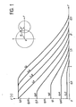
- the intercorrelation by FOURIER holography, between an object to be tested and a reference object is a means of determining whether, in a given family, there are objects identical to the reference, and if so, how many there are, and where they are located. This technique is difficult to use effectively, mainly due to its lack of selectivity. To show this, we will take the case of circular objects for which the reference objects are disks.
- ring is meant a narrow closed band, which can have various shapes, circular in most cases, but also elliptical or other.
- Such a ring can be limited by two concentric circles, one inscribed, the other circumscribed.
- the "dimensions" of the ring then refer to the radii of these circles and the "center” of the ring refers to the common center of said circles.
- “narrow” means that the difference in the radii of the two circles delimiting the ring is small compared to the radius of the circumscribed circle. If the ring is circular, its outer and inner edges naturally merge with the circumscribed and inscribed circles.
- the subject of the invention is a method of optical processing of objects in which, after having recorded a hologram of a reference object appropriate, we illuminate this hologram by a plane wave having a field reproducing the spatial Fourier transform of the objects to be treated and we form the spatial Fourier transform of the hologram thus lit, which provides an image representing the intercorrelation function between the treated objects and the reference object, this method being characterized in that said objects having contours close to a known contour, we take as reference object at least one ring having this known contour and a width allowing to encompass said neighboring contours.
- the reference object is constituted by at least one differential ring, this differential ring being constituted by two concentric rings and of different sizes, these rings being treated, during the recording of the hologram, to give optical contributions of the same energy but of opposite phases.
- the two rings forming the differential ring can be contiguous or non-contiguous.
- the reference object consists of several offset, homogeneous or differential rings.
- the rings are also circular. They are defined by their radius R which is that of the outer circle and by their width E, difference between the radii of the inner and outer circles.
- the width E of the ring is chosen according to the fineness of resolution sought. Very generally, the E / R ratio is between 0.01 and 0.3.
- the selectivity of the method is chosen according to the precision of circularity of the family of objects; it can in certain particular cases of spherical or circular objects reach for example 0.001.
- the present invention also relates to a device which implements this method.
- This device comprises means for forming a plane wave having a field which reproduces the Fourier transform space of the objects to be processed, and to illuminate by this wave a hologram of a reference object, means for forming in an image plane the spatial Fourier transform of the hologram thus lit, an optoelectronic receiver arranged behind the image plane , this device being characterized in that the hologram used is that of an object consisting of at least one ring having the outline of the objects to be treated.
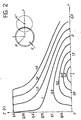
- FIG. 2 shows that the method of the invention has an appreciable advantage over the previous method linked to the fact that the intercorrelation function has, for disks of radius equal to or greater than that of the reference ring , a marked maximum and the "noise" due to discs of lower spokes can be practically eliminated.
- the probability distribution corresponds to the variation, as a function of the reference radius, of the number of disks in the family whose radius is between this reference radius and a neighboring radius whose deviation relative to the reference radius is predetermined.
- the maximum of the intercorrelation function is very marked for the rings of radius R and low for the rings of neighboring radii less than or greater than R.
- this technique has the disadvantage of being difficult to implement. Indeed, the optical transformation of a disk into a ring actually corresponds to a derivation of the signal. This derivation can only be validly made if the signal is pure or, otherwise expressed, only if the disc is perfect. Indeed, if this is not the case, the derivation will only accentuate the faults without making it possible to achieve a satisfactory result.
- the objects to be studied are rarely in the form of perfect discs and the use of this technique may not be satisfactory.
- the invention in an implementation variant, however allows an equivalent result to be achieved, while avoiding these drawbacks.
- This variant uses a differential reference ring. It is a ring consisting of a first ring of radius R 1 and of width E 1 small in front of R 1 , of a second concentric ring of radius R 2 greater than R 1 and of width E 2 small in front of R 2 , the two rings being joined or not; these two rings are treated so that their optical contributions during the formation of the hologram, are of equal energies but in phase opposition. This point will be taken up later.
- the width of the rings will be chosen according to the precision and finesse of resolution sought. In general, the rings have the same surface.
- the characteristics of the differential ring are then simple to define. Indeed, it suffices to set the width and the radius of a rings, E 2 and R 2 for example, to automatically deduce therefrom the radius R 1 of the other ring and its width E 1 .
- E 2 being chosen generally weak compared to R2 ′ El will have a value very close to E 2 .
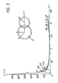
- the spatial resolution obtained by this variant of the method is illustrated by the curve of the maxima of the differential disk-ring intercorrelation function as a function of the ratio R '/ R 1 .
- the width of the peak at mid-height (linked to the spatial separating power) is of the order of E2 , which means that the energy which passes through the object disk is concentrated at its center in the autocorrelation plane.
- the reference rings preferably used in the method of the invention and its variant are produced by means of a microbelinograph.
- a microbelinograph With this device, each information point on a photographic plate is illuminated with a luminance calculated by computer, the photographic plate is then developed, then it is placed in the optical assembly intended to establish the hologram.
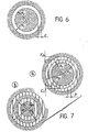
- a homogeneous reference ring which can be used in the invention is illustrated in FIG. 6 with the notations already defined: width E equal to R 1 - R 0 , R O being the radius of the inner circle and R 1 the radius of the outer circle.
- a differential reference ring that can be used in the invention is produced by light diffracted by the objects illustrated in FIG. 7: with contiguous rings on part (a) and non-contiguous rings on part (b).
- These rings are density modulated by a sinusoid of pitch "p" symbolically represented by vertical hatching.
- the modulation of the first ring is in spatial phase opposition with that of the second ring.
- the rings are illuminated by a plane wave inclined obliquely on the plane of the rings so that the diffracted light has a wave plane parallel to the plane of the rings.
- the spatial phase opposition of the sinusoids modulating the rings induces a temporal phase opposition on the light diffracted by said rings, which makes the ring "differential".
- the energy of the wave diffracted by such a differential ring must be the same for the two rings which compose it, so that one generally takes rings of the same surface; but one could take rings of different surfaces, provided that this difference is compensated by an attenuation of the sinusoid on the largest ring to restore the equality of the diffracted waves.
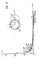
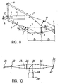
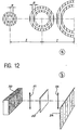
- the hologram of the rings used in the invention (homogeneous or differential) is established with an apparatus which, by way of nonlimiting example, is illustrated in FIG. 8.
- a monochromatic light source (laser) 1 provides a coherent beam of light 2. A fraction of it passes through a separating plate 3, is reflected by a mirror 4 and passes through a spatial filter 5 then a lens 6 whose focal length is such that the optical assembly thus formed makes it possible to illuminate, at an angle O1, by a plane wave the object plane 7 which contains the reference ring. The diffracted light at 7 is collected by an objective 8 whose focal distance is f this objective forms the FOURIER transform of the plane 7 in a plane 9.
- the separating plate 3 operating in reflection sends another fraction of the beam 2 onto a mirror 10 , the reflected beam passes through a spatial filter 11, then a lens 12 whose focal length is such that the optical assembly 3, 10, 11, 12 thus formed produces a plane wave surface which illuminates at an angle 0 2 the plane 9
- the optical paths using elements 3, 4, 5, 6, 7, 8, 9 and 3, 10, 11, 12, 9 are equal and there is interference in the plane 9.
- a holographic plate in plan 9 for recording the hologram of the ring placed in plan 7, which, developed, will be used in the method of the invention.
- this angle ⁇ 1 is zero, which corresponds, in the previous relation, to an infinite step p.
- Reference rings can be made using the thin film technique.
- This technique consists in covering a transparent plate with a thin metallic layer obtained for example by vacuum evaporation, taking care, during the operation, to hide the surface corresponding to the desired ring.
- To make the differential ring it suffices to prepare a ring according to the same process, the surface of which is that of the two rings of the differential ring and then to deposit on one of these rings, taking care to hide the rest of the surface, a dielectric material whose thickness is that of a half-wave plate. The two rings will thus be in phase opposition.
- a differential ring hologram from a simple ring with a conventional assembly by operating in two stages.
- the hologram of the first ring is conventionally established then, during the second step, the hologram of the second ring is established on the same holographic plate, ensuring that they are concentric and contiguous and that they have the same surface and by introducing for the second ring a phase shift of ⁇ by means of a phase plate placed on the reference beam.
- This alternative embodiment of the reference ring is however more difficult to implement than the first.
- the hologram of the reference ring being established, it is used in a device making it possible to obtain an intercorrelation between the objects to be tested and the reference ring.
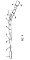
- Several assemblies are possible. They are derived more or less from the double diffraction arrangement illustrated in FIG. 9.
- the operating principle of this device is as follows: in plane 15 is placed a family of objects, for example discs of different radii, and in plane 17 the hologram of a homogeneous ring of radius R.
- the focal lengths objectives 16 and 18 are set to the value fo used for recording the hologram of the ring (cf. FIG. 8).
- the dimension of the FOURIER transform of the family of these disks is the same as that of the ring recorded on the hologram. There will then be a maximum intercorrelation in the plane 19 where as many light points as disks of radius at least equal to R will appear, these points being located at the same coordinates as the centers of the disks in question in the plane 15.
- a threshold amplifier can be used to eliminate the parasitic terms of the feet from the cross-correlation functions. It then suffices to clip the remaining peaks and count them digitally or analogically.
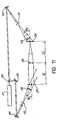
- the light rays pass twice through the same objective with variable focal length which performs the transformation of FOURIER on the outward and return journey.
- the assembly comprises: an object slot 50 having a certain width, a first objective 51, a plane 52 in which is placed the multiple hologram in question obtained with reference rings whose centers are spaced apart by an equal interval at the width of the slot 50, a second objective 53, an image plane 54 in which one obtains as many images as the reference rings used. These images are adjacent and offset along a direction perpendicular to the slit. Each of these images represents the function of intercorrelation of the object to be studied, diaphragmed by the slot 50 with one of the reference rings.
- the photodetector (not shown) can then advantageously be of the vidicon type operating by line-by-line scanning of the image plane in a direction parallel to the object slot. Thus, after a single scan of the plane, the distribution function of the objects of the family studied is obtained.
- the corresponding measurements can be carried out either directly on the sample by placing it in a transparent sheath arranged in the object plane of the device, or by means of photographs of these samples.
- the method of the invention can naturally be applied to the study of objects which, although not circular, are in the form of neighboring homothetic surfaces delimited by simple closed curves. Indeed, it will then suffice to complete the optical assemblies illustrated above with an appropriate optical system - prism or mirror - allowing the object plane or the hologram plane to rotate.
- the invention is also applicable to the recognition of shapes and in particular letters, numbers or various signs.
Landscapes
- Physics & Mathematics (AREA)
- General Physics & Mathematics (AREA)
- Engineering & Computer Science (AREA)
- Multimedia (AREA)
- Theoretical Computer Science (AREA)
- Optics & Photonics (AREA)
- Holo Graphy (AREA)
- Character Discrimination (AREA)
- Instruments For Measurement Of Length By Optical Means (AREA)
- Length Measuring Devices By Optical Means (AREA)
Applications Claiming Priority (2)
| Application Number | Priority Date | Filing Date | Title |
|---|---|---|---|
| FR7915519A FR2459449A1 (fr) | 1979-06-18 | 1979-06-18 | Procede et dispositif optiques de denombrement, de localisation et de classement selon leur taille d'objets de forme circulaire, bases sur une intercorrelation par holographie |
| FR7915519 | 1979-06-18 |
Publications (1)
| Publication Number | Publication Date |
|---|---|
| EP0021982A1 true EP0021982A1 (fr) | 1981-01-07 |
Family
ID=9226724
Family Applications (1)
| Application Number | Title | Priority Date | Filing Date |
|---|---|---|---|
| EP80400884A Ceased EP0021982A1 (fr) | 1979-06-18 | 1980-06-17 | Procédé et dispositif de traitement optique d'objets par intercorrélation avec des anneaux |
Country Status (4)
| Country | Link |
|---|---|
| EP (1) | EP0021982A1 (enExample) |
| JP (1) | JPS56500710A (enExample) |
| FR (1) | FR2459449A1 (enExample) |
| WO (1) | WO1980002882A1 (enExample) |
Cited By (3)
| Publication number | Priority date | Publication date | Assignee | Title |
|---|---|---|---|---|
| GB2195802A (en) * | 1986-09-24 | 1988-04-13 | Gen Electric Plc | Pattern recognition system |
| EP0273186A3 (de) * | 1986-11-20 | 1989-05-31 | Fried. Krupp Gesellschaft mit beschränkter Haftung | Berührungsloses optisches Verfahren zur Bestimmung von Gegenständen |
| US9522930B2 (en) | 2012-07-30 | 2016-12-20 | Leibniz-Institut Für Naturstoff-Forschung Und Infektionsbiologie | Chartreusin analogues |
Citations (2)
| Publication number | Priority date | Publication date | Assignee | Title |
|---|---|---|---|---|
| US3871769A (en) * | 1972-05-19 | 1975-03-18 | Turlabor Ag | Apparatus for determining the diameters of small particles |
| US4111526A (en) * | 1977-05-12 | 1978-09-05 | General Motors Corporation | Rotationally independent optical correlation for position determination |
Family Cites Families (1)
| Publication number | Priority date | Publication date | Assignee | Title |
|---|---|---|---|---|
| US4118107A (en) * | 1966-01-19 | 1978-10-03 | Technical Operations, Incorporated | Optical detection of geometric configurations |
-
1979
- 1979-06-18 FR FR7915519A patent/FR2459449A1/fr active Granted
-
1980
- 1980-06-17 EP EP80400884A patent/EP0021982A1/fr not_active Ceased
- 1980-06-17 JP JP50134680A patent/JPS56500710A/ja active Pending
- 1980-06-17 WO PCT/FR1980/000096 patent/WO1980002882A1/fr not_active Ceased
Patent Citations (2)
| Publication number | Priority date | Publication date | Assignee | Title |
|---|---|---|---|---|
| US3871769A (en) * | 1972-05-19 | 1975-03-18 | Turlabor Ag | Apparatus for determining the diameters of small particles |
| US4111526A (en) * | 1977-05-12 | 1978-09-05 | General Motors Corporation | Rotationally independent optical correlation for position determination |
Non-Patent Citations (4)
| Title |
|---|
| APPLIED OPTICS, Vol. 12, No. 4, Avril 1973 New York (US) A. ENGEL: "Additional filters enhancing the sensitivity of an optical correlator", pages 743-748 * Pages 746-747 * * |
| APPLIED OPTICS, Vol. 15, No. 2, Fevrier 1976 New York (US) S. ALMEIDA et al.: "Water pollution monitoring using matched spatial filters", pages 510-515 * Pages 511, 513 * * |
| IEEE TRANSACTIONS ON INFORMATION THEORY, Vol. 10, 1964 New York (US) VAN DER LUGT: "Signal detection by complex spatial filtering", pages 139-145 * Page 140-141, 143 * * |
| JOURNAL OF THE OPTICAL SOCIETY OF AMERICA, Vol. 61, Nr. 4, Avril 1971 New York (US) S.K. YAO et al.: "Spatial differentiation and integration by coherent optical-correlation method", pages 474-477 * Page 475 * * |
Cited By (3)
| Publication number | Priority date | Publication date | Assignee | Title |
|---|---|---|---|---|
| GB2195802A (en) * | 1986-09-24 | 1988-04-13 | Gen Electric Plc | Pattern recognition system |
| EP0273186A3 (de) * | 1986-11-20 | 1989-05-31 | Fried. Krupp Gesellschaft mit beschränkter Haftung | Berührungsloses optisches Verfahren zur Bestimmung von Gegenständen |
| US9522930B2 (en) | 2012-07-30 | 2016-12-20 | Leibniz-Institut Für Naturstoff-Forschung Und Infektionsbiologie | Chartreusin analogues |
Also Published As
| Publication number | Publication date |
|---|---|
| FR2459449B1 (enExample) | 1985-02-15 |
| WO1980002882A1 (fr) | 1980-12-24 |
| FR2459449A1 (fr) | 1981-01-09 |
| JPS56500710A (enExample) | 1981-05-21 |
Similar Documents
| Publication | Publication Date | Title |
|---|---|---|
| EP1399730B1 (fr) | Procede et dispositif destines a l'obtention par microscopie d'images en trois dimensions d'un echantillon | |
| EP1364181B1 (fr) | Procede et dispositif d'imagerie microscopique interferentielle d'un objet a haute cadence. | |
| EP0985902B1 (fr) | Dispositif interférométrique pour relever les caractéristiques de réflexion et/ou de transmission optiques en profondeur d'un objet | |
| EP3274694B1 (fr) | Procédé de détermination de l'état d'une cellule | |
| EP0928433A1 (fr) | Microscope generant une representation tridimensionnelle d'un objet | |
| FR2484633A1 (fr) | Procede et dispositif de mesure de profil de surface sans contact | |
| WO2014067886A1 (fr) | Systeme d'imagerie holographique auto-reference | |
| EP0028548A1 (fr) | Système de correlation optique en temps réel | |
| EP3069185A1 (fr) | Dispositif et methode de mise au point tridimensionnelle pour microscope | |
| WO2022122981A1 (fr) | Microscope confocal avec réallocation de photons | |
| EP3754431B1 (fr) | Procédé de reconstruction holographique | |
| EP3371574B1 (fr) | Dispositif et procédé d'observation d'un objet par imagerie sans lentille | |
| EP3520022A1 (fr) | Procédé de numération de leucocytes dans un échantillon | |
| EP0021982A1 (fr) | Procédé et dispositif de traitement optique d'objets par intercorrélation avec des anneaux | |
| EP3491330B1 (fr) | Systèmes et procédés d'imagerie interférentielle plein champ | |
| EP0069071B1 (fr) | Procédé d'identification d'un objet et de mesure de sa position et de son orientation, et dispositif pour la mise en oeuvre de ce procédé | |
| EP3903098B1 (fr) | Procédé de caractérisation d'un échantillon par imagerie de phase | |
| EP2677368A1 (fr) | Dispositif et procédé de lecture d'un hologramme synthétique | |
| FR2684202A1 (fr) | Procede et dispositif holographiques perfectionnes en lumiere incoherente. | |
| FR2836575A1 (fr) | Procede de mesure de la localisation d'un objet par detection de phase | |
| EP0751400B1 (fr) | Procédé et dispositif de traitement optique d'images bidimensionnelles permettant l'extraction du champ de vitesse | |
| WO2025046038A1 (fr) | Procédé d'obtention d'une image haute résolution d'un échantillon et dispositif d'imagerie | |
| CH410460A (fr) | Elément optique à zones et utilisation de cet élément | |
| FR2728361A1 (fr) | Interferometre holographique polychrome et procede de visualisation de variations de chemin optique dans un objet par interferometrie holographique | |
| EP1321760A1 (fr) | Procédé de mesure de la fluorescence issue de microéchantillons et dispositif associé |
Legal Events
| Date | Code | Title | Description |
|---|---|---|---|
| PUAI | Public reference made under article 153(3) epc to a published international application that has entered the european phase |
Free format text: ORIGINAL CODE: 0009012 |
|
| AK | Designated contracting states |
Designated state(s): BE CH DE FR GB IT |
|
| 17P | Request for examination filed |
Effective date: 19810609 |
|
| STAA | Information on the status of an ep patent application or granted ep patent |
Free format text: STATUS: THE APPLICATION HAS BEEN REFUSED |
|
| 18R | Application refused |
Effective date: 19831210 |
|
| RIN1 | Information on inventor provided before grant (corrected) |
Inventor name: BONNET, GEORGES Inventor name: DE BAZELAIRE, ERIC |