EP0021419B1 - Dithered laser gyro - Google Patents
Dithered laser gyro Download PDFInfo
- Publication number
- EP0021419B1 EP0021419B1 EP80103595A EP80103595A EP0021419B1 EP 0021419 B1 EP0021419 B1 EP 0021419B1 EP 80103595 A EP80103595 A EP 80103595A EP 80103595 A EP80103595 A EP 80103595A EP 0021419 B1 EP0021419 B1 EP 0021419B1
- Authority
- EP
- European Patent Office
- Prior art keywords
- bellows
- ring laser
- laser gyro
- gyro
- pair
- Prior art date
- Legal status (The legal status is an assumption and is not a legal conclusion. Google has not performed a legal analysis and makes no representation as to the accuracy of the status listed.)
- Expired
Links
- 230000003287 optical effect Effects 0.000 claims description 36
- 230000003534 oscillatory effect Effects 0.000 claims description 12
- 230000000694 effects Effects 0.000 claims description 8
- 238000005086 pumping Methods 0.000 claims description 4
- 230000001939 inductive effect Effects 0.000 claims description 3
- 238000000034 method Methods 0.000 claims description 3
- 230000001360 synchronised effect Effects 0.000 claims description 2
- 239000007789 gas Substances 0.000 description 18
- 238000013459 approach Methods 0.000 description 10
- 230000005284 excitation Effects 0.000 description 9
- 239000000463 material Substances 0.000 description 4
- 238000004891 communication Methods 0.000 description 3
- 239000007772 electrode material Substances 0.000 description 2
- 239000002184 metal Substances 0.000 description 2
- 239000000203 mixture Substances 0.000 description 2
- 238000000926 separation method Methods 0.000 description 2
- 230000002123 temporal effect Effects 0.000 description 2
- 230000001427 coherent effect Effects 0.000 description 1
- 230000009977 dual effect Effects 0.000 description 1
- 238000005265 energy consumption Methods 0.000 description 1
- 229910052734 helium Inorganic materials 0.000 description 1
- 239000001307 helium Substances 0.000 description 1
- SWQJXJOGLNCZEY-UHFFFAOYSA-N helium atom Chemical compound [He] SWQJXJOGLNCZEY-UHFFFAOYSA-N 0.000 description 1
- 230000006698 induction Effects 0.000 description 1
- 229910052754 neon Inorganic materials 0.000 description 1
- GKAOGPIIYCISHV-UHFFFAOYSA-N neon atom Chemical compound [Ne] GKAOGPIIYCISHV-UHFFFAOYSA-N 0.000 description 1
- 239000005304 optical glass Substances 0.000 description 1
- 230000010355 oscillation Effects 0.000 description 1
- 230000000644 propagated effect Effects 0.000 description 1
- 238000007789 sealing Methods 0.000 description 1
- 230000035945 sensitivity Effects 0.000 description 1
- 230000009897 systematic effect Effects 0.000 description 1
Images
Classifications
-
- H—ELECTRICITY
- H01—ELECTRIC ELEMENTS
- H01S—DEVICES USING THE PROCESS OF LIGHT AMPLIFICATION BY STIMULATED EMISSION OF RADIATION [LASER] TO AMPLIFY OR GENERATE LIGHT; DEVICES USING STIMULATED EMISSION OF ELECTROMAGNETIC RADIATION IN WAVE RANGES OTHER THAN OPTICAL
- H01S3/00—Lasers, i.e. devices using stimulated emission of electromagnetic radiation in the infrared, visible or ultraviolet wave range
- H01S3/10—Controlling the intensity, frequency, phase, polarisation or direction of the emitted radiation, e.g. switching, gating, modulating or demodulating
-
- G—PHYSICS
- G01—MEASURING; TESTING
- G01C—MEASURING DISTANCES, LEVELS OR BEARINGS; SURVEYING; NAVIGATION; GYROSCOPIC INSTRUMENTS; PHOTOGRAMMETRY OR VIDEOGRAMMETRY
- G01C19/00—Gyroscopes; Turn-sensitive devices using vibrating masses; Turn-sensitive devices without moving masses; Measuring angular rate using gyroscopic effects
- G01C19/58—Turn-sensitive devices without moving masses
- G01C19/64—Gyrometers using the Sagnac effect, i.e. rotation-induced shifts between counter-rotating electromagnetic beams
- G01C19/66—Ring laser gyrometers
- G01C19/68—Lock-in prevention
-
- H—ELECTRICITY
- H01—ELECTRIC ELEMENTS
- H01S—DEVICES USING THE PROCESS OF LIGHT AMPLIFICATION BY STIMULATED EMISSION OF RADIATION [LASER] TO AMPLIFY OR GENERATE LIGHT; DEVICES USING STIMULATED EMISSION OF ELECTROMAGNETIC RADIATION IN WAVE RANGES OTHER THAN OPTICAL
- H01S3/00—Lasers, i.e. devices using stimulated emission of electromagnetic radiation in the infrared, visible or ultraviolet wave range
- H01S3/05—Construction or shape of optical resonators; Accommodation of active medium therein; Shape of active medium
- H01S3/08—Construction or shape of optical resonators or components thereof
- H01S3/081—Construction or shape of optical resonators or components thereof comprising three or more reflectors
- H01S3/083—Ring lasers
- H01S3/0835—Gas ring lasers
Definitions
- the present invention relates to ring laser gyroscopes and more particularly pertains to laser gyroscopes which are dithered to reduce the effects of mode locking.
- a pair of counter-rotating light beams are propagated about a closed- loop path.
- the two beams traveling in opposite directions are compared in frequency.
- the gyroscope rotates in inertial space, the two oppositely traveling beams see apparently unequal paths. This causes the laser to resonate at different frequencies for the two beams.
- the frequency difference may be measured as an indication of the direction and rate of the rotation.
- Optically active devices such as, for example, Faraday cells have been inserted into laser cavities to introduce a bias or asymmetry into the operation of the laser to thereby avoid mode locking.
- An example of such an approach is given in U.S. patent 4,222,668.
- Another example, using a birefringent optical element appears in Newburgh, "Ring Laser Utilizing An Optical Retardation Plate to Prevent Beam Locking", U.S. Patent 3,791,738 issued February 12, 1974. In Newburgh, a varying Fresnel phase velocity shift is obtained by dithering the optical element.
- the optical elements increase the number of interfaces between dissimilar materials in the optical path. Each such interface tends to be a source of increased scattering. The increased scattering tends to enhance the very mode locking effects which are intended to be reduced.
- the optical elements themselves introduce bias errors into the operation of the gyro due to such factors as, for example, asymmetry in their characteristics and random variations in their characteristics due, for example, to variations in temperature.
- Electrical excitation, or pumping power, for lasing is typically applied to the laser gaseous medium from a direct current supply.
- a voltage sufficient to sustain a discharge in the medium is applied to spaced-apart electrodes.
- the discharge, or plasma excitation current comprises a flow of ionized gas between oppositely polarized electrodes in the optical cavity. It has long been known that this plasma flow tends to induce bias in a ring laser gyro. Therefore, laser gyros which use direct current excitation are typically provided with a balanced electrode structure wherein two electrodes of one polarity are symmetrically disposed about a single electrode of the opposite polarity. With this structure, two equal and opposite plasma excitation currents are caused to flow and their biases are thereby caused to cancel.
- the electrical excitation to sustain the plasma excitation currents may be obtained from a supply which varies the voltage in such a way as to dynamically unbalance those currents.
- a dynamically varying bias in the gyro output, i.e., dither, may thereby be induced.
- the maximum amount of dither obtainable by the use of dynamically varying unbalance in the plasma excitation currents is too small for this approach to be of practical interest.
- a pair of close-end bellows are mounted on the envelope of a laser gyro at the laser gain section.
- Each bellows is capable of extension and retraction to locally enlarge and contract the volume of the laser optical cavity.
- a reciprocated driver arm is coupled to the pair of bellows to operate them in push-pull creating a dynamically varying pressure differential along the bore of the gain section of the optical cavity.
- This approach to frequency unlocking a gyro has the advantages of structural simplicity, low weight, small size and relatively low cost. It has relatively low power requirements. Its audible noise level and vibration level are low. No material interfaces which might cause reflections and scattering are required to be added to the optical path. Since gas flows back and forth in the optical cavity, there is a tendency to reduce thermal gradients therein. This could lead to a temperature bias sensitivity lower than can be achieved with body dithering.
- Another object of the invention is to provide mechanical means for pumping the plasma of a ring laser gyro to produce a dynamically varying bias of the gyro output and consequent reduction of the effects of mode locking due to the resulting oscillatory gas flow therein.
- a ring laser gyroscope 10 having a body 12 which is preferably of optical glass having a low coefficient of thermal expansion. Passageways or bores 14, 16 and 18 in the body 12 form a closed polygonal cavity 19 for counter-propagating beams of coherent light. Corner mirrors 20, 22 and 24 at the extremities of each of the bores 14, 16 and 18 reflect the beams of light onto each succeeding leg of the optical path.
- Corner mirror 24 is made partially transmissive in order to provide an exit port for a portion of the circulating light energy. Some of the energy of the clockwise circulating light beam exits the optical cavity 19 through mirror 24 and impinges directly on photodetector 26. Some of the energy of the counterclockwise circulating light beam exits the optical cavity 19 through mirror 24 and first strikes corner cube reflector 28. It is reflected back to the mirror 24 and then deflected onto photodetector 26 where it is mixed with the energy from the clockwise circulating light beam. The mixture of the energy from the two counter-propagating light beams is then detected in photodetector 26 to provide an output signal which is a measure of the rotation rate of the gyro 10.
- the base 12 forms a sealed envelope containing gas under low pressure in the optical cavity 19.
- a suitable gas for the laser 10 is the well-known mixture of helium and neon. Electrodes are disposed in communication with the optical cavity 19 so that an electrical discharge for plasma excitation and lasing may be maintained in the gas.
- a single centrally-located cathode 30 of a suitable metal communicates with the bore 18 through passageway 32.
- an anode 36 communicates with the bore 14 and another anode 38 communicates with the bore 16.
- the anodes 36 and 38 are symmetrically disposed about the cathode 30 at locations on the optical path 19 which are selected to provide a desired length for the gain section of the laser relative to the length of the entire optical cavity.
- the laser gain section is the portion of the optical cavity 19 in which the electrodes 30, 36 and 38, when energized, will maintain a discharge in the ionized gas, or plasma.
- Balanced electrical voltages are applied between the anodes 36 and 38 and the cathode 30 to provide substantially equal, and therefore balanced, plasma excitation currents flowing in the laser gain section.
- the anodes 36 and 38 may be structures serving as electrodes only. However, in the preferred embodiment, anodes 36 and 38 are formed as flexible bellows of a suitable metal. Bellows 36 and 38 are dynamically flexed to provide a flow of the gas in the laser gain section. They are mechanically linked to each other through a bellows driver arm 40. Oscillatory or reciprocating motion is imparted to driver arm 40 by means of a piezo bimorph driver 42. Of course, when the bellows 36 and 38 are implemented as structures which do not function as electrodes, there is no need to impart any motion to the other distinct structures which do serve as electrodes.
- the driver 42 is also connected through a corner cube driver link 44 to a post 46 on which the corner cube reflector 28 is mounted. The function of these interrelated parts is shown more clearly in Figure 2.
- the body 12 of the laser gyro 10 is provided with wells 48 and 50 communicating with the optical cavity 19.
- Well 48 includes a passageway 49 in direct communication with bore 14 while well 50 includes a passageway 51 in direct communication with bore 16.
- the bellows 36 is disposed in well 48.
- Bellows 36 has an end plate or diaphragm 52 sealed across and closing the lower end thereof. Bellows 36 and diaphragm 52 are attached to each other and to the laser body 12 in such a way as to maintain the optical cavity 19 sealed from the external environment.
- the bellows 38 and diaphragm 54 closing the lower end thereof are attached to each other and to the laser body 12 in such a way as to form a portion of the envelope sealing the optical cavity 19 from the external environment.
- Closed-end bellows 36 and 38 are each disposed to be displaced from and outside the optical path of the laser 10.
- Each of diaphragms 52 and 54 are engaged with opposing extensions 53 and 55, respectively, of the bellows driver arm 40 so that reciprocating rotation of the driver arm 40 about a driver arm flexure 56, as indicated by curved, double-ended arrow 58, causes push-pull motion of the two closed-end bellows 36 and 38.
- bellows drive arm 40 is rotated counterclockwise, bellows 38 is extended and diaphragm 54 forces gas into the optical cavity 19.
- diaphragm 52 draws gas out of the optical cavity 19.
- bellows driver arm 40 is rotated clockwise, bellows 36 is extended and diaphragm 52 forces gas into the optical cavity 19.
- diaphragm 54 draws gas out of the cavity 19.
- diaphragms 52 and 54 in combination with bellows 36 and 38, respectively function as mechanical pumps operating in push-pull to dynamically vary the pressure differential along the optical cavity of the laser 10 and to produce an oscillatory and dynamically reciprocating flow of the gas therein.
- An oscillatory flow of the plasma in the laser gain section will produce an oscillatory bias or dither in the output of the ring laser gyro 10.
- the ionised gas in the gain section can be given an oscillatory flow of sufficient amplitude to produce a desired level of frequency modulation in the beams.
- a readily achievable pressure variation amplitude at each bellows of 80 dyne/cm 2 at a frequency of 100 Hz can typically produce a modulation index of at least 300. With this modulation index, the effective lock rate may be reduced to less than 0.1 deg/hr. This performance may be improved further by superimposing a random dither on the sinusoidal dither.
- Piezo bimorph drivers are well known in the art. They are fabricated by forming a laminate which includes two layers of piezoelectric material and an intermediate layer of electrode material interposed between the two piezoelectric layers. Layers of electrode material are also disposed on the outer surfaces of the laminate. When a voltage is applied between the intermediate electrode and the two outer electrodes, the laminate bows because one layer of piezoelectric material shrinks while the other elongates. If the voltage is reversed, the bimorph bows in the opposite direction.
- each outer electrode of the driver 42 is formed as two separate electrodes so that each side of the driver can be energized with a voltage 180° out of phase with the voltage applied to the other side. When so energized, the bowing of the driver 42 tends to follow an S-curve as indicated by dashed line 60 in Figure 2.
- the bimorph driver 42 and the driver arm 40 bear against each other at their centers as indicated at 66.
- the bimorph driver 42 is attached to the base 12 by two laterally compliant mounting posts 62 and 64. Oscillatory rotation of the bellows driver arm 40 about its laterally compliant centrally located flexure 56, as indicated by double-ended arrow 58, is produced when an alternating voltage is applied to the driver electrodes (not shown) in the manner described above. Structural details of the bimorph driver 42 are not shown in Figure 2.
- a similar, but more elaborate, device is shown and discussed in U.S. Patent 4,113,387, "Dual Mode Laser Optics Control for Ring Laser Gyro", issued September 12, 1978, to S. G. Shutt, the inventor herein, and assigned to Rockwell International Corporation, the assignee herein.
- the bimorph driver 42 is shown coupled to the post 46 through corner cube driver link 44.
- corner cube driver link 44 draws the post 46 toward the base 12.
- the post 46 is caused to rotate about a point near its bottom as indicated by double-ended arrow 68.
- the corner cube 28 is mounted on the post 46. Corner cube 28 is not shown in Figure 2. There is thus provided a means for drawing the corner cube 28 toward the base 12 with a reciprocating motion which is synchronized to the dither applied to the gas in the laser gain section. A compensating doppler frequency drift is thereby induced in the laser output beam which impinges on corner reflector 28.
- the amplitude of this doppler shift is adjusted to be such that when the affected beam is mixed with the other beam, the dither bias signal induced by the gas flow oscillation does not appear in the gyro output.
- This approach is analogous to the approach used in mechanical body dithered ring laser gyros wherein the dither bias signal is typically removed by the use of a stationary corner cube reacting with a light beam exiting on a dynamically varying path.
Landscapes
- Physics & Mathematics (AREA)
- Engineering & Computer Science (AREA)
- Electromagnetism (AREA)
- Optics & Photonics (AREA)
- Plasma & Fusion (AREA)
- Power Engineering (AREA)
- General Physics & Mathematics (AREA)
- Radar, Positioning & Navigation (AREA)
- Remote Sensing (AREA)
- Gyroscopes (AREA)
- Lasers (AREA)
Description
- The present invention relates to ring laser gyroscopes and more particularly pertains to laser gyroscopes which are dithered to reduce the effects of mode locking.
- In a laser gyroscope, a pair of counter-rotating light beams are propagated about a closed- loop path. The two beams traveling in opposite directions are compared in frequency. When the gyroscope rotates in inertial space, the two oppositely traveling beams see apparently unequal paths. This causes the laser to resonate at different frequencies for the two beams. The frequency difference may be measured as an indication of the direction and rate of the rotation.
- For small rotation rates, however, mode or frequency locking occurs. The frequencies of the two oppositely-directed light beams lock to each other and the beams resonate together. This creates a nonlinear dead zone in the characteristic of the gyro for which no useful output can be obtained.
- Among the schemes used to avoid or reduce the effect of the lock-in phenomenon is mechanical body dithering of the gyro. The entire gyro body is mechanically oscillated at a relatively high frequency. This gives the gyro a dynamically varying bias rotation rate which exceeds the threshold input rate or natural lock rate of the dead zone most of the time. This mechanical dither approach has been used successfully. However, it adds undesirable energy consumption, cost, weight, size and mechanical complexity to an attitude reference system employing it. Mechanical dithering also introduces an undesirable source of vibration and noise into a system. This vibration may cause problems in the use of other instruments, such as accelerometers, which may be mounted with the gyro on the same apparatus. An example of a ring laser gyro employing mechanical dither is given in Hutchings et al., "Counterbalanced Oscillating Ring Laser Gyro", U.S. Patent 4,115,004 issued September 19, 1978.
- Optically active devices such as, for example, Faraday cells have been inserted into laser cavities to introduce a bias or asymmetry into the operation of the laser to thereby avoid mode locking. An example of such an approach is given in U.S. patent 4,222,668. Another example, using a birefringent optical element, appears in Newburgh, "Ring Laser Utilizing An Optical Retardation Plate to Prevent Beam Locking", U.S. Patent 3,791,738 issued February 12, 1974. In Newburgh, a varying Fresnel phase velocity shift is obtained by dithering the optical element.
- In U.S. Patent 4,219,275 an optically active device inserted into the laser cavity introduces either a spatial or temporal separation of the counter-propagating light beams. This approach is intended to eliminate mode locking altogether. An approach to simultaneous temporal and spatial separation of the beams using shutters is disclosed in Chodorow, "Means for Avoiding Locking in Ring Lasers", U.S. Patent 3,627,422 issued December 14, 1971.
- A problem arises in the approaches to unlocking gyros which insert optical elements in the laser cavity such as the approaches described in US Patents 4,222,668, 3,791,738, 4,219,275 and 3,627,422. The optical elements increase the number of interfaces between dissimilar materials in the optical path. Each such interface tends to be a source of increased scattering. The increased scattering tends to enhance the very mode locking effects which are intended to be reduced. Furthermore, the optical elements themselves introduce bias errors into the operation of the gyro due to such factors as, for example, asymmetry in their characteristics and random variations in their characteristics due, for example, to variations in temperature.
- Electrical excitation, or pumping power, for lasing is typically applied to the laser gaseous medium from a direct current supply. A voltage sufficient to sustain a discharge in the medium is applied to spaced-apart electrodes. The discharge, or plasma excitation current, comprises a flow of ionized gas between oppositely polarized electrodes in the optical cavity. It has long been known that this plasma flow tends to induce bias in a ring laser gyro. Therefore, laser gyros which use direct current excitation are typically provided with a balanced electrode structure wherein two electrodes of one polarity are symmetrically disposed about a single electrode of the opposite polarity. With this structure, two equal and opposite plasma excitation currents are caused to flow and their biases are thereby caused to cancel.
- It is known that the electrical excitation to sustain the plasma excitation currents may be obtained from a supply which varies the voltage in such a way as to dynamically unbalance those currents. A dynamically varying bias in the gyro output, i.e., dither, may thereby be induced. However, the maximum amount of dither obtainable by the use of dynamically varying unbalance in the plasma excitation currents is too small for this approach to be of practical interest.
- A scheme for biasing a ring laser gyro which involves pumping the plasma more vigorously is disclosed in Podgorski, "Externally Biased Ring Laser", U.S. Patent 3,744,908 issued July 10, 1973. A linear induction motor positioned adjacent to the laser gain section pumps the ionized gas unidirectionally. The apparent index of refraction for the two oppositely traveling beams is thereby made different by an amount sufficient to avoid lock-in. This scheme is believed to use large amounts of energy. The requirement for an electromagnet structure increases the weight. In addition, in a scheme such as this where a unidirectional bias is induced, no cancellation of systematic errors occurs.
- By means of the invention, the above-noted shortcomings of the prior art are overcome, and there is provided more efficient mechanical means for inducing relatively large oscillatory flow superimposed on the balanced flow of the ionized gas in the gain section of a ring laser gyro. The output of the gyro is thereby dithered to reduce the effects of mode locking therein.
- In a preferred embodiment of the invention, a pair of close-end bellows, spaced-apart from each other, are mounted on the envelope of a laser gyro at the laser gain section. Each bellows is capable of extension and retraction to locally enlarge and contract the volume of the laser optical cavity. A reciprocated driver arm is coupled to the pair of bellows to operate them in push-pull creating a dynamically varying pressure differential along the bore of the gain section of the optical cavity.
- This approach to frequency unlocking a gyro has the advantages of structural simplicity, low weight, small size and relatively low cost. It has relatively low power requirements. Its audible noise level and vibration level are low. No material interfaces which might cause reflections and scattering are required to be added to the optical path. Since gas flows back and forth in the optical cavity, there is a tendency to reduce thermal gradients therein. This could lead to a temperature bias sensitivity lower than can be achieved with body dithering.
- Accordingly, it is an object of the invention to provide a new and improved means for reducing the effects of frequency locking in a ring laser.
- Another object of the invention is to provide mechanical means for pumping the plasma of a ring laser gyro to produce a dynamically varying bias of the gyro output and consequent reduction of the effects of mode locking due to the resulting oscillatory gas flow therein.
-
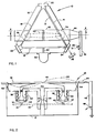
- Figure 1 is a plan view of a ring laser gyroscope in accord with the invention.
- Figure 2 is a cross-section view of the gyroscope taken on the line 2-2 of Figure 1 looking in the direction of the arrows.
- Referring now to Figure 1, there is shown a
ring laser gyroscope 10 having abody 12 which is preferably of optical glass having a low coefficient of thermal expansion. Passageways or bores 14, 16 and 18 in thebody 12 form a closedpolygonal cavity 19 for counter-propagating beams of coherent light. Corner mirrors 20, 22 and 24 at the extremities of each of thebores -
Corner mirror 24 is made partially transmissive in order to provide an exit port for a portion of the circulating light energy. Some of the energy of the clockwise circulating light beam exits theoptical cavity 19 throughmirror 24 and impinges directly onphotodetector 26. Some of the energy of the counterclockwise circulating light beam exits theoptical cavity 19 throughmirror 24 and first strikescorner cube reflector 28. It is reflected back to themirror 24 and then deflected ontophotodetector 26 where it is mixed with the energy from the clockwise circulating light beam. The mixture of the energy from the two counter-propagating light beams is then detected inphotodetector 26 to provide an output signal which is a measure of the rotation rate of thegyro 10. - The base 12 forms a sealed envelope containing gas under low pressure in the
optical cavity 19. A suitable gas for thelaser 10 is the well-known mixture of helium and neon. Electrodes are disposed in communication with theoptical cavity 19 so that an electrical discharge for plasma excitation and lasing may be maintained in the gas. A single centrally-locatedcathode 30 of a suitable metal communicates with thebore 18 throughpassageway 32. Similarly, ananode 36 communicates with thebore 14 and anotheranode 38 communicates with thebore 16. Theanodes cathode 30 at locations on theoptical path 19 which are selected to provide a desired length for the gain section of the laser relative to the length of the entire optical cavity. The laser gain section is the portion of theoptical cavity 19 in which theelectrodes anodes cathode 30 to provide substantially equal, and therefore balanced, plasma excitation currents flowing in the laser gain section. - The
anodes anodes bellows driver arm 40. Oscillatory or reciprocating motion is imparted todriver arm 40 by means of apiezo bimorph driver 42. Of course, when thebellows driver 42 is also connected through a cornercube driver link 44 to apost 46 on which thecorner cube reflector 28 is mounted. The function of these interrelated parts is shown more clearly in Figure 2. - Referring now to Figure 2, the
body 12 of thelaser gyro 10 is provided withwells optical cavity 19. Well 48 includes apassageway 49 in direct communication withbore 14 while well 50 includes apassageway 51 in direct communication withbore 16. The bellows 36 is disposed inwell 48.Bellows 36 has an end plate ordiaphragm 52 sealed across and closing the lower end thereof. Bellows 36 anddiaphragm 52 are attached to each other and to thelaser body 12 in such a way as to maintain theoptical cavity 19 sealed from the external environment. Similarly, in well 50, thebellows 38 anddiaphragm 54 closing the lower end thereof are attached to each other and to thelaser body 12 in such a way as to form a portion of the envelope sealing theoptical cavity 19 from the external environment. Closed-end bellows 36 and 38 are each disposed to be displaced from and outside the optical path of thelaser 10. - Each of
diaphragms opposing extensions 53 and 55, respectively, of thebellows driver arm 40 so that reciprocating rotation of thedriver arm 40 about adriver arm flexure 56, as indicated by curved, double-endedarrow 58, causes push-pull motion of the two closed-end bellows 36 and 38. When the bellows drivearm 40 is rotated counterclockwise, bellows 38 is extended anddiaphragm 54 forces gas into theoptical cavity 19. At the same time, since bellows 36 is retracted,diaphragm 52 draws gas out of theoptical cavity 19. Conversely, when thebellows driver arm 40 is rotated clockwise, bellows 36 is extended anddiaphragm 52 forces gas into theoptical cavity 19. At the same time, since bellows 38 is retracted,diaphragm 54 draws gas out of thecavity 19. Thus, when bellowsdriver arm 40 is dynamically oscillated back and forth,diaphragms bellows laser 10 and to produce an oscillatory and dynamically reciprocating flow of the gas therein. An oscillatory flow of the plasma in the laser gain section will produce an oscillatory bias or dither in the output of thering laser gyro 10. - Analysis has shown that the ionised gas in the gain section can be given an oscillatory flow of sufficient amplitude to produce a desired level of frequency modulation in the beams. A readily achievable pressure variation amplitude at each bellows of 80 dyne/cm2 at a frequency of 100 Hz can typically produce a modulation index of at least 300. With this modulation index, the effective lock rate may be reduced to less than 0.1 deg/hr. This performance may be improved further by superimposing a random dither on the sinusoidal dither.
- A variety of ways are known for producing the requisite rotary oscillatory or reciprocating motion in the
bellows driver arm 40. As mentioned above, the preferred technique uses apiezo bimorph driver 42 engaged withdriver arm 40. Piezo bimorph drivers are well known in the art. They are fabricated by forming a laminate which includes two layers of piezoelectric material and an intermediate layer of electrode material interposed between the two piezoelectric layers. Layers of electrode material are also disposed on the outer surfaces of the laminate. When a voltage is applied between the intermediate electrode and the two outer electrodes, the laminate bows because one layer of piezoelectric material shrinks while the other elongates. If the voltage is reversed, the bimorph bows in the opposite direction. In the preferred embodiment, each outer electrode of thedriver 42 is formed as two separate electrodes so that each side of the driver can be energized with a voltage 180° out of phase with the voltage applied to the other side. When so energized, the bowing of thedriver 42 tends to follow an S-curve as indicated by dashedline 60 in Figure 2. - The
bimorph driver 42 and thedriver arm 40 bear against each other at their centers as indicated at 66. Thebimorph driver 42 is attached to thebase 12 by two laterally compliant mountingposts bellows driver arm 40 about its laterally compliant centrally locatedflexure 56, as indicated by double-endedarrow 58, is produced when an alternating voltage is applied to the driver electrodes (not shown) in the manner described above. Structural details of thebimorph driver 42 are not shown in Figure 2. A similar, but more elaborate, device is shown and discussed in U.S. Patent 4,113,387, "Dual Mode Laser Optics Control for Ring Laser Gyro", issued September 12, 1978, to S. G. Shutt, the inventor herein, and assigned to Rockwell International Corporation, the assignee herein. - The
bimorph driver 42 is shown coupled to thepost 46 through cornercube driver link 44. As thedriver arm 40 vibrates, cornercube driver link 44 draws thepost 46 toward thebase 12. Thepost 46 is caused to rotate about a point near its bottom as indicated by double-endedarrow 68. As was indicated in Figure 1, thecorner cube 28 is mounted on thepost 46.Corner cube 28 is not shown in Figure 2. There is thus provided a means for drawing thecorner cube 28 toward the base 12 with a reciprocating motion which is synchronized to the dither applied to the gas in the laser gain section. A compensating doppler frequency drift is thereby induced in the laser output beam which impinges oncorner reflector 28. The amplitude of this doppler shift is adjusted to be such that when the affected beam is mixed with the other beam, the dither bias signal induced by the gas flow oscillation does not appear in the gyro output. This approach is analogous to the approach used in mechanical body dithered ring laser gyros wherein the dither bias signal is typically removed by the use of a stationary corner cube reacting with a light beam exiting on a dynamically varying path. - Although the invention has been disclosed and illustrated in detail, it is to be clearly understood that the same is by way of illustration and example only and is not to be taken by way of limitation.
Claims (8)
Applications Claiming Priority (2)
| Application Number | Priority Date | Filing Date | Title |
|---|---|---|---|
| US06/054,331 US4325033A (en) | 1979-07-02 | 1979-07-02 | Pneumatically dithered laser gyro |
| US54331 | 1998-04-02 |
Publications (3)
| Publication Number | Publication Date |
|---|---|
| EP0021419A2 EP0021419A2 (en) | 1981-01-07 |
| EP0021419A3 EP0021419A3 (en) | 1981-01-14 |
| EP0021419B1 true EP0021419B1 (en) | 1983-05-04 |
Family
ID=21990320
Family Applications (1)
| Application Number | Title | Priority Date | Filing Date |
|---|---|---|---|
| EP80103595A Expired EP0021419B1 (en) | 1979-07-02 | 1980-06-25 | Dithered laser gyro |
Country Status (3)
| Country | Link |
|---|---|
| US (1) | US4325033A (en) |
| EP (1) | EP0021419B1 (en) |
| DE (1) | DE3062962D1 (en) |
Families Citing this family (9)
| Publication number | Priority date | Publication date | Assignee | Title |
|---|---|---|---|---|
| US5347360A (en) * | 1982-08-27 | 1994-09-13 | Ratheon Company | Ring laser gyro |
| US5331660A (en) * | 1984-07-24 | 1994-07-19 | Rockwell International Corporation | Ring laser gyro gas bypass with auxiliary discharge |
| US5309218A (en) * | 1984-12-17 | 1994-05-03 | Northrop Corporation | Gas ring laser gyroscopes |
| US4751713A (en) * | 1987-07-31 | 1988-06-14 | Hughes Aircraft Company | Gas laser having a piezoelectric fan |
| FR2645261B1 (en) * | 1989-03-30 | 1991-07-26 | Salaberry Bernard De | MIXING AND READING DEVICE FOR A LASER GYROMETER |
| US5317381A (en) * | 1989-09-18 | 1994-05-31 | Allied-Signal Inc. | Pneumatically dithered ring laser gyroscope |
| US6771684B2 (en) * | 2000-03-02 | 2004-08-03 | Alan E. Hill | Compact, flexible, rapid-pulsed, molecular gas laser |
| US7215697B2 (en) * | 1999-08-27 | 2007-05-08 | Hill Alan E | Matched impedance controlled avalanche driver |
| US8837549B2 (en) | 2011-11-23 | 2014-09-16 | Ipg Microsystems Llc | Continuous mass flow gas replenishment for gas lasing devices |
Family Cites Families (9)
| Publication number | Priority date | Publication date | Assignee | Title |
|---|---|---|---|---|
| US3627422A (en) * | 1965-06-21 | 1971-12-14 | Varian Associates | Means for avoiding locking in ring lasers |
| US3466121A (en) * | 1965-09-28 | 1969-09-09 | Bell Telephone Labor Inc | Nonreciprocal optical devices |
| US3496488A (en) * | 1966-10-05 | 1970-02-17 | Bell Telephone Labor Inc | Frequency-stabilized optical maser |
| US3517331A (en) * | 1966-11-16 | 1970-06-23 | Canadian Patents Dev | Method and apparatus for the stabilization of lasers,etalons,and similar optical devices |
| US3744908A (en) * | 1968-12-16 | 1973-07-10 | Honeywell Inc | Externally biased ring laser |
| US3686585A (en) * | 1971-05-27 | 1972-08-22 | Ali Javan | Method of stabilizing a gas laser |
| US3791738A (en) * | 1973-04-11 | 1974-02-12 | Us Air Force | Ring laser utilizing an optical retardation plate to prevent beam locking |
| US4115004A (en) * | 1976-11-15 | 1978-09-19 | Litton Systems, Inc. | Counterbalanced oscillating ring laser gyro |
| US4113387A (en) * | 1977-02-14 | 1978-09-12 | Rockwell International Corporation | Dual mode laser optics control for ring laser gyro |
-
1979
- 1979-07-02 US US06/054,331 patent/US4325033A/en not_active Expired - Lifetime
-
1980
- 1980-06-25 EP EP80103595A patent/EP0021419B1/en not_active Expired
- 1980-06-25 DE DE8080103595T patent/DE3062962D1/en not_active Expired
Also Published As
| Publication number | Publication date |
|---|---|
| EP0021419A3 (en) | 1981-01-14 |
| DE3062962D1 (en) | 1983-06-09 |
| US4325033A (en) | 1982-04-13 |
| EP0021419A2 (en) | 1981-01-07 |
Similar Documents
| Publication | Publication Date | Title |
|---|---|---|
| US4115004A (en) | Counterbalanced oscillating ring laser gyro | |
| US6683692B2 (en) | Dither system for motion sensors | |
| US4477188A (en) | Monolithic three axis ring laser gyroscope | |
| JPS6145399B2 (en) | ||
| US4325033A (en) | Pneumatically dithered laser gyro | |
| US4281930A (en) | Laser gyro with phased dithered mirrors | |
| US4801206A (en) | Simplified ring laser gyroscope dither control and method | |
| US3533014A (en) | Gas ring laser using oscillating radiation scattering sources within the laser cavity | |
| US4653919A (en) | Laser gyro with dithered mirrors and current dither | |
| US4821281A (en) | Hollow cathode glow discharge ring laser angular rate sensor | |
| SE451888B (en) | RING LASER GYRO | |
| US4686683A (en) | Laser angular rate sensor with dithered mirrors | |
| CA1309155C (en) | Ring laser | |
| US5116128A (en) | Mirror transducer assembly for ring laser gyroscope | |
| US4641970A (en) | Ring laser lock-in correction apparatus | |
| US4575855A (en) | Ring laser gyro cathode arrangement | |
| EP0266942B1 (en) | Ring laser gyroscope with geometrically induced bias | |
| Roland et al. | Optical gyroscopes | |
| GB2072936A (en) | Acoustically dithered ring laser gyro | |
| US4864586A (en) | Hollow cathode glow discharge ring laser block and electrode structure for ring laser angular rate sensors | |
| WO1985003568A1 (en) | Ring laser gyro tilt mirror dither | |
| JPS598077B2 (en) | Ring Laser Gyro | |
| US5317381A (en) | Pneumatically dithered ring laser gyroscope | |
| JPH08506934A (en) | Ring laser discharge start concept | |
| RU2812252C1 (en) | Small ring laser |
Legal Events
| Date | Code | Title | Description |
|---|---|---|---|
| PUAI | Public reference made under article 153(3) epc to a published international application that has entered the european phase |
Free format text: ORIGINAL CODE: 0009012 |
|
| PUAL | Search report despatched |
Free format text: ORIGINAL CODE: 0009013 |
|
| AK | Designated contracting states |
Designated state(s): DE FR GB IT |
|
| AK | Designated contracting states |
Designated state(s): DE FR GB IT |
|
| 17P | Request for examination filed |
Effective date: 19810314 |
|
| ITF | It: translation for a ep patent filed | ||
| GRAA | (expected) grant |
Free format text: ORIGINAL CODE: 0009210 |
|
| AK | Designated contracting states |
Designated state(s): DE FR GB IT |
|
| REF | Corresponds to: |
Ref document number: 3062962 Country of ref document: DE Date of ref document: 19830609 |
|
| ET | Fr: translation filed | ||
| PLBE | No opposition filed within time limit |
Free format text: ORIGINAL CODE: 0009261 |
|
| STAA | Information on the status of an ep patent application or granted ep patent |
Free format text: STATUS: NO OPPOSITION FILED WITHIN TIME LIMIT |
|
| 26N | No opposition filed | ||
| ITTA | It: last paid annual fee | ||
| PGFP | Annual fee paid to national office [announced via postgrant information from national office to epo] |
Ref country code: FR Payment date: 19980520 Year of fee payment: 19 |
|
| PGFP | Annual fee paid to national office [announced via postgrant information from national office to epo] |
Ref country code: GB Payment date: 19980526 Year of fee payment: 19 |
|
| PGFP | Annual fee paid to national office [announced via postgrant information from national office to epo] |
Ref country code: DE Payment date: 19980527 Year of fee payment: 19 |
|
| PG25 | Lapsed in a contracting state [announced via postgrant information from national office to epo] |
Ref country code: GB Free format text: LAPSE BECAUSE OF NON-PAYMENT OF DUE FEES Effective date: 19990625 |
|
| PG25 | Lapsed in a contracting state [announced via postgrant information from national office to epo] |
Ref country code: FR Free format text: THE PATENT HAS BEEN ANNULLED BY A DECISION OF A NATIONAL AUTHORITY Effective date: 19990630 |
|
| GBPC | Gb: european patent ceased through non-payment of renewal fee |
Effective date: 19990625 |
|
| PG25 | Lapsed in a contracting state [announced via postgrant information from national office to epo] |
Ref country code: DE Free format text: LAPSE BECAUSE OF NON-PAYMENT OF DUE FEES Effective date: 20000503 |
|
| REG | Reference to a national code |
Ref country code: FR Ref legal event code: ST |