EP0020498B1 - Post form stay inserter for shirt collars - Google Patents
Post form stay inserter for shirt collars Download PDFInfo
- Publication number
- EP0020498B1 EP0020498B1 EP79901352A EP79901352A EP0020498B1 EP 0020498 B1 EP0020498 B1 EP 0020498B1 EP 79901352 A EP79901352 A EP 79901352A EP 79901352 A EP79901352 A EP 79901352A EP 0020498 B1 EP0020498 B1 EP 0020498B1
- Authority
- EP
- European Patent Office
- Prior art keywords
- collar
- stays
- template
- stay
- moving
- Prior art date
- Legal status (The legal status is an assumption and is not a legal conclusion. Google has not performed a legal analysis and makes no representation as to the accuracy of the status listed.)
- Expired
Links
- 239000000463 material Substances 0.000 claims abstract description 65
- 239000000853 adhesive Substances 0.000 claims abstract description 47
- 230000001070 adhesive effect Effects 0.000 claims abstract description 47
- 238000000034 method Methods 0.000 claims description 18
- 238000010438 heat treatment Methods 0.000 claims description 14
- 238000003780 insertion Methods 0.000 claims description 8
- 230000037431 insertion Effects 0.000 claims description 8
- 238000009958 sewing Methods 0.000 claims description 4
- 239000003381 stabilizer Substances 0.000 description 9
- XEEYBQQBJWHFJM-UHFFFAOYSA-N Iron Chemical compound [Fe] XEEYBQQBJWHFJM-UHFFFAOYSA-N 0.000 description 2
- 238000004873 anchoring Methods 0.000 description 1
- 238000005452 bending Methods 0.000 description 1
- 239000011248 coating agent Substances 0.000 description 1
- 238000000576 coating method Methods 0.000 description 1
- 229910052742 iron Inorganic materials 0.000 description 1
- ORQBXQOJMQIAOY-UHFFFAOYSA-N nobelium Chemical compound [No] ORQBXQOJMQIAOY-UHFFFAOYSA-N 0.000 description 1
- 230000010355 oscillation Effects 0.000 description 1
- 230000000750 progressive effect Effects 0.000 description 1
- 239000007779 soft material Substances 0.000 description 1
- 239000002699 waste material Substances 0.000 description 1
Images



Classifications
-
- A—HUMAN NECESSITIES
- A41—WEARING APPAREL
- A41H—APPLIANCES OR METHODS FOR MAKING CLOTHES, e.g. FOR DRESS-MAKING OR FOR TAILORING, NOT OTHERWISE PROVIDED FOR
- A41H43/00—Other methods, machines or appliances
-
- A—HUMAN NECESSITIES
- A41—WEARING APPAREL
- A41B—SHIRTS; UNDERWEAR; BABY LINEN; HANDKERCHIEFS
- A41B3/00—Collars
- A41B3/06—Stiffeners for collars
Definitions
- This invention relates to a system which automatically and continually forms and positions collar stays at a collar template structure, and relates to a method in which the worker inserts a partially completed shirt collar about the collar template structure and withdraws both the collar and collar stays from the template structure with the collar stays properly positioned in the collar structure.
- Top stitching is formed about the collar after the stays have been inserted and held by adhesive.
- the shirt structure is thereby formed with its collar stays sewn into the structure by the top stitching of the shirt collar and with adhesive.
- collar stays In order to fabricate shirt collars from soft materials and yet have the collars formed so that they are attractive, it has become common for manufacturers to insert collar stays into the collar structure so that the collar stays extend down into the pointed portions of the collar.
- the collar stays are usually semi-rigid flat strips of material with one pointed end portion inserted into the pointed part of a collar and with its other end being rounded so as to be comfortable to the wearer and so it will not harm the appearance of the collar.
- pockets are sewn into the underside of the collar structure to accommodate the collar stays.
- the collar stays In other usually less expensive shirts the collar stays are sewn to the liner or to 'quarter patches' which occupy the pointed portions of a collar.
- the collar stays are completed omitted and the quarter patch material is relied upon to function as a collar stay.
- the collar stays are attached to the quarter patch or liner prior to the attachment of the quarter patch or liner to the rest of the collar structure.
- the worker usually sews or otherwise attaches a collar stay to the material, then attaches the material to the other plies of collar material, and then the product is everted and placed on a template where it is stretched, formed and pressed.
- the worker must be careful not to damage the collar, as by causing the pointed portion of the collar stay to break through the material, or by bending the collar stay etc.
- the collar stay is improperly attached to the liner or quarter patch, and therefore is improperly positioned inside the finished collar structure.
- the collar stays might be placed at the wrong angle in the collar structure or the collar stay may protrude too deeply or not deeply enough into the pointed portions of the collar structure.
- collar stays when collar stays are present in the collar structure, more time is required by the worker to evert, form and press the collar structure.
- an inventory of collar stays must be maintained and occasionally replenished by the worker that attaches the collar stays to the collar structure and when different style collars are being handled by the worker, it is sometimes necessary to change the length of the collar stays being inserted into the collar structure, which requires a new inventory of collar stays.
- US-A-3191557 discloses apparatus for forming shirt collars and cuffs. This specification also discloses collar stays which have a coating of adhesive on one side.
- US-A-2875928 discloses apparatus for inserting collar stays into collars.
- the specification describes apparatus which includes means to cut collar stays from a supply of collar stay material.
- the specification discloses apparatus having a bodkin over which the collar is placed so that the collar stay can be pushed into the collar by a push member.
- a method of inserting collar stays into partially completed collars comprising the steps of moving a pair of collar stays with pointed ends extending in their directions of movement along the surface of a collar template, inserting a partially completed collar about the template, simultaneously pressing the collar against both of the collar stays, and removing the collar with the collar stays inside the collar from the template, characterised by the steps of grasping one end of each collar stay by grasping means prior to moving the stays along the surface of the template, moving the stays along the surface of the template while grasped, until the pointed ends of the collar stays are in registration with pointed portions of the collar template, and inserting a partially completed collar about the collar template while the collar stays are grasped.
- apparatus for inserting collar stays into partially completed collars comprising a collar template having a surface adapted to permit a pair of collar stays to move therealong, said collar template being shaped to permit insertion of a partially completed collar about the template, said template being adapted to permit simultaneous pressing of the collar against both of the collar stays and to permit removal of the collar, with both collar stays inside the collar, from the template, characterised by grasping means adapted to grasp the collar stays and to move them along the surface of the collar template while grasped until the pointed ends of the stays are in registration with pointed portions of the template, and said partially completed collars can be inserted about the template while the stays are grasped.
- a method of forming collar stays and of inserting collar stays into partially completed collars comprising the steps of moving a pair of collar stays with pointed ends extending in their directions of movement along the surface of a collar template, inserting a partially completed collar about the template, simultaneously pressing the collar against both of the collar stays, and removing the collar with the collar stays inside the collar from the template, characterised by the forming steps comprising moving a length of material along its length from a supply of material through a path, cutting the material into segments with each segment including a pointed end portion and a rounded end portion to form a collar stay, and the inserting steps comprising grasping one end of each collar stay by grasping means prior to moving the stays along the surface of the template, moving the stays along the surface of the template while grasped, until the pointed ends of the collar stays are in registration with pointed portions of the collar template, and inserting a partially completed collar about the collar template while the collar stays are grasped.
- apparatus for forming collar stays and for inserting collar stays into partially completed collars comprising a collar template having a surface adapted to permit a pair of collar stays to move therealong, said collar template being shaped to permit insertion of a partially completed collar about the template, said template being adapted to permit simultaneous pressing of the collar against both of the collar stays and to permit removal of the collar, with both collar stays inside the collar, from the template, characterised by the apparatus for forming the collar stays comprising indexing means for intermittently urging a length of collar stay material along its length and through a rectilinear path a predetermined distance, cutting means positioned along said path for cutting the length of collar stay material into collar stay segments, and adhesive applicator means positioned along said path for applying adhesive to each collar stay segment, and the apparatus for inserting the collar stays comprising grasping means adapted to grasp the collar stays and to move them along the surface of the collar template while grasped until the pointed ends of the stays are in registration with pointed portions of the template, and said partially completed
- the present invention provides an expedient, inexpensive, automatic and accurate system for placing collar stays in shirt collar structures.
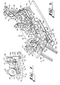
- FIG. 1 schematically illustrates the post form stay inserter for shirt collar 10 which includes stay cutting means 11 and collar stay loading means 12.
- an elongated length or strip of collar stay material 14 is fed from a supply such as reel 15 through a downward loop 16 and then along a rectilinear path 18.
- a supply such as reel 15
- a clamp or brake 20 Positioned in sequence along the path are an iron or heating means 19, a clamp or brake 20, an indexing means 21, a cutting means 22, and an adhesive applicator means 24.
- the indexing means 21 comprises wheel 25 that rotates only in one direction as indicated by arrow 26 and is reciprocated as indicated by double-headed arrows 28, so that the wheel tends to intermittently pull the strip material 14 along the path 18 through the heating means 19 and clamp 20 and push the strip on into the cutting means 22.
- Clamp 20 engages the strip 14 as the indexing means 21 moves in the reverse direction so as to hold the strip in position while heating means 19 and cutting means 22 are actuated to heat and cut the strip into segments such as segment or stay 29.
- the adhesive applicator means 24 also applies a spot of adhesive 30 to the segment 29.
- the segments 29 are then moved by the collar stay loading means 12 (Fig. 8) to the template elements 31 and 32, first by moving a collar stay 29 to the position indicated at 29a, then by moving a second collar stay to the position indicated at 29b, whereupon both collar stays 29a and 29b are reoriented to positions indicated at 29c and 29d, and then moved onto the relative flat template elements 31 and 32 until their pointed ends overlie the pointed end portions of the template elements.
- the worker then inserts a partially completed collar structure 34 about the template elements 31 and 32, presses the collar material against the spots of adhesive 30 so as to cause the collar stays to adhere to the material of the collar, and then removes the collar with the collar stays properly positioned therein from the template structure and passes the collar to another work station where the top stitching 35 (Fig. 2) is formed in the collar 34 in the usual manner by a sewing machine which is schematically represented by the sewing machine needle 36.
- the collar stays 39 are located deep in the points of the collar structure and the top stitching 35 passes through both the collar material and the collar stays to anchor the stays in their proper locations within the collar structure.
- the collar is formed from the two outer plies of material 38 and 39, the liner 40 and the collar stay 29.
- a quarter patch (not shown) can be part of the collar structure.
- the collar stay cutting means 22 comprises a work table 44 which supports the various elements of the cutting means.
- the reel 15 of collar stay material is mounted on a hanger structure 45 which includes an upright stanchion 46, upper cross arm 47 and rotatable spindle 48.
- Stabilizer arm 49 is pivotally attached to cross arm 47 by means of pivot pin 50.
- Reel stabilizer 49 includes guide arm 51 and stabilizer arm 52.
- Loop generator 54 is also mounted on reel support structure 45 and comprises vertically oriented loop generator cylinder 55 which has its rod 56 movable from its lower end and with loop bracket 58 mounted on the end of rod 56.
- loop generator cylinder 55 When loop generator cylinder 55 is actuated to distend its rod 56, the bracket 58 moves downwardly into the bight of loop 16 to cause the material 14 to pay out from the reel and to extend the loop 16.
- Plate 59 is mounted on work table 44, and a pair of spaced apart elongated rectilinear straps 60 and 61 are placed on plate 59.
- the space between the straps 60 and 61 form a slot 62, and the strip of material 14 feeding from reel 15 passes through the slot.
- slot 62 forms the rectilinear path of movement of the material across work table 44.
- Indexing means 21 comprises first indexer 64 mounted on work table 44 and includes cylinder mounting bracket 65 which is attached to the surface of the work table, first index cylinder 66, carriage assembly 68, and index wheel 25.
- Carriage assembly 68 includes carriage block 69 slidably mounted on a pair of parallel carriage rods 70.
- the rod 71 of first index cylinder 66 is attached to carriage block 69 and functions to reciprocate the carriage block 69 along the carriage rods 70.
- Index wheel 25 includes a clutch element 72 which is attached thereto and permits the index wheel to rotate in the direction indicated by arrow 26, while prohibiting rotation in the opposite direction.
- Index wheel 25 is supported by a lever 74 which is pivotally mounted to carriage block 69.
- Leaf spring 75 is mounted on the top of carriage block 69 and continuously urges lever 74 in a downward direction, thereby pressing index wheel 25 into the slot 62.
- the parallel carriage rods 70 are mounted at their ends in blocks 76 (only one shown), and valve 77 is located adjacent one end of the rods 70 with its actuator 78 in the path of the protrusion 73 from carriage block 69 so as to limit the movement of the carriage block 69 and to become actuated by the movement of the carriage block protrusion against the valve actuator 78.
- the movement of the carriage block 69 in the other direction is limited by the position of lock block 79 which is releasably attached to the parallel carriage rods 70 by a set screw (not shown) so that the lock block can be positioned at various locations along the length of the rods 70 to limit the reverse movement of the carriage block 69.
- the length of the strip of material being cut by the system can be varied.
- Heating means 19 is located along the path of movement of the strip 14 of material and includes heating element 80 supported above the path of movement of the strip of material by bracket 81 and platen 82 positioned beneath the path of the strip of material. Presser cylinder 84 is located below platen 82 and its rod 85 is attached to the platen 82 and reciprocates the platen toward and away from heating element 80. Thus, heating means 19 functions to intermittently heat the length of the strip 14 moved along the path across the work table 44 as the presser cylinder 84 intermittently lifts the platen 82 up against pressing relationship with the strip 14 and heating element 80.
- Clamp 20 is located between heating means 19 and indexing means 21 and comprises support bracket 86 which supports clamp cylinder 88 above the path of movement of the strip 14.
- Brake shoe is mounted on the lower end of the cylinder rod 90, and platform 91 is located below shoe 89.
- the strip of material 14 passes between shoe 89 and platform 91.
- the brake shoe 89 moves downwardly into engagement with the strip 14 which causes the movement of the strip 14 along its path 62 to stop.
- Cutting means 22 is located adjacent the end of the stroke of indexing means 21 and includes a die block or cross head 92 (Figs. 5 and 6) attached to the upper ends of shafts 94 and 95.
- Bottom cross head 96 is located beneath the work table 22 and is attached to the lower ends of the shafts 94, 95.
- Anvil cylinder 98 is attached by means of bracket 99 to the bottom surface of work table 22 and its rod 100 is connected to bottom cross head 96.
- Anvil 101 is located beneath die block 92, and cutter 102 is attached to and movable with die block 92.
- cylinder 98 retracts its cylinder rod 100, the bottom and top cross heads 96 and 92 and the shafts 94 and 95 move downwardly so that the cutter 102 cuts the strip 14, with the waste of the strip passing downwardly through the opening 104.
- adhesive applicator means 24 comprises support shaft 105 which is pivotally mounted to work table 44 by pivot pin 106 and bracket 108, support block 109 which defines a vertical opening therethrough (not shown) which slidably receives support shaft 105, support arm 110 that is mounted to support block 109 and extends laterally therefrom, cross head 111 which is mounted to the upper end of support shaft 105, and dispenser cylinder 112 which is suspended from cross head 111.
- the cylinder rod 114 is connected to support arm 110 and functions to reciprocate support arm 110 and support block 109 vertically along the length of support shaft 105.
- Reel mounting fork 115 extends vertically from support arm 110, and spindle 116 is slidably held in reel mounting fork 115.
- Adhesive transfer tape 118 is mounted on spindle 116.
- Support roller 119 is rotatably mounted on support arm 110, the reel of adhesive transfer tape 118 rests on the support roller.
- Stamp block 120 is rigidly mounted to support arm 110 and is positioned below support roller 119.
- Feed roller 121 and idler roller 122 are rotatably mounted on support arm 110.
- Crank cylinder 124 is mounted on support arm 110, and its cylinder rod 125 is connected to crank 126. The other end of crank 126 is connected to feed roller 121.
- Crank 126 and feed roller 121 are constructed so that oscillation of crank 126 functions to rotate feed roller 121 only in the direction indicated by arrow 128.
- a free end 129 of the adhesive transfer tape 118 passes downwardly about support roller 119, then about the stamp block 120, then upwardly over feed roller 121 and then downwardly between the feed roller and the idler roller 122..
- cylinder 112 When cylinder 112 is actuated, its rod 114 distends which moves support block 109 and support arm 110 downwardly against the bias of spring 107 so that stamp block 120 presses the tape against a collar stay segment 29 which has been previously cut by the collar stay cutting means 22.
- the adhesive transfer tape is the type of tape to which adhesive adheres, but when the tape is pressed against another surface to which the adhesive will more readily adhere, the adhesive separates from the tape and clings to the other surface.
- An example of a suitable adhesive transfer tape is Y-909, 1 1/2 mil by 3M Company.
- Second indexing means 130 is mounted on work table 44 and includes carriage assembly 131 which comprises support block 132, horizontal carriage bar 134 and platform 135. Second index cylinder 136 is mounted on support block 132 and its cylinder rod 138 is connected at its distal end to carriage block 139. Carriage block 139 is movably mounted on carriage bar 134 and reciprocates on rod 134 under the influence of the reciprocal movement of cylinder rod 138. A trolley 140 is mounted on carriage block 139 and rolls along platform 135. Trolley 140 tends to stabilize carriage block 139 as it reciprocates.
- Spring finger rod 141 is rotatably received at one of its end in carriage block 139, and spring finger 142 is rigidly mounted at one of its ends to the other end of spring finger rod 141.
- Finger clamp cylinder 144 is mounted on carriage block 139 and its cylinder rod 145 is connected to one end of crank arm 146.
- Crank arm 146 is connected at its other end to spring finger rod 141.
- the collar stay loading means 12 is located at the end of work table 44 (Fig. 5) and generally comprises movable loading chutes 148 and 149, pairs of grasping fingers 150 and 151 and collar templates 31 and 32.
- Loading chute support assembly 152 comprises a pair of support brackets 154 and 1 55 mounted to a common support (not shown) and a pair of parallel guide bars 156 and 157 extending horizontally between and supported at their ends by the support brackets 154 and 155.
- Loading chutes 148 and 149 are slidably mounted on guide bars 156 and 157, by the insertion of the guide bars through openings in the loading chutes. In this manner, loading chutes 148 and 149 are maintained in parallel, side-by-side relationship, and both are movable along the lengths of the guide bars 156 and 157.
- Cylinder support brackets 158 and 159 are also mounted on guide bars 156 and 157 by the insertion of the guide bars through openings in the cylinder support brackets. Chute cylinders 160 and 161 are supported by cylinder support brackets 158 and 159, and cylinder rods 162 and 163 bear against movable loading chutes 148 and 149.
- Spring support forks 165 are mounted on support brackets 154 and 155, and coil tension springs 166, 167, 168 and 169 are connected at their ends to movable loading chutes 148 and 149 and to spring support forks 165.
- the springs 166-169 tend to urge the movable loading chutes toward the sides of the assembly while the cylinders 160 and 161 operate to urge the movable loading chutes toward the center of the assembly.
- Each movable loading chute 148 and 149 is inclined and defines a slot 170 and 171, respectively, with the slot of each loading chute extending entirely along its length.
- a stop bracket 172, 173 is located at the lower end of each loading chute 148 and 149, respectively.
- Each stop bracket includes a top wall 175, an end wall 176, and a side wall 177.
- Each stop bracket is open at its upper end and at one of its sides and is movable laterally over the lower end of its loading chute.
- Stay stop cylinders 178 and 179 are mounted on the lower ends of chutes 148 and 149 respectively and their cylinder rods (not shown) are connected to the stop brackets 172 and 173 and operate to reciprocate the stop brackets 172 and 173 over the lower ends of chutes 148 and 149.
- the stop bracket 173 of loading chute 149 reciprocates in the direction indicated by arrows 180 between positions where the stop bracket covers the lower end of the slot 171 (Fig. 9) and where the stop bracket uncovers the lower end of the slot.
- Finger and template support carriage 181 is mounted beneath loading chute support assembly 152 and includes end support blocks 182 and 183, a pair of carriage bars 184 and 185 which are mounted at their ends and maintained in parallel relationship by the end support blocks, and a pair of carriage structures 186 and 187.
- Each carriage structure 186 and 187 includes a pair of carriage blocks 189 and 190 which are slidably received on carriage bars 184 and 185 and a carriage platform 191 attached to the bottoms of the carriage blocks 189 and 190.
- the carriage platforms 191 are therefore movable toward and away from each other by sliding the carriage blocks 189 and 190 along the lengths of carriage bars 184 and 185.
- Each carriage platform 191 has mounted thereon a stanchion support 192 and an upright stanchion 194.
- the stanchion support is bolted at one of its ends to platform 191 and the other end is bifurcated to receive the lower end of the stanchion 194.
- Finger opening pin 195 is mounted on stanchion 194 and valve support bracket 196 is mounted to the upper end of the stanchion.
- Chute valves 198 and 199 are each mounted on valve support brackets 196 and have their valve actuator buttons facing the movable chutes 148 and 149. When the movable chutes 148 and 149 are moved by their springs 166-169 toward the outside of the assembly, the movable chutes will engage the actuators of valves 198 and 199.
- the carriage platform 191 at each side of the assembly also carries grasping finger carriage assembly 200 and 201.
- Each grasping finger carriage assembly includes a pair of upright carriage bars 202 and 203 which are mounted at their lower ends in support blocks 205. The upper ends of the carriage bars are connected together by stabilizer block 206.
- Carriage block 208 is mounted on the carriage bars 202 and 203 and is movably verticaly along the length of the carriage bars.
- Carriage block cylinders 209 and 210 are each mounted to a carriage platform 191, and their cylinder rods 211 and 212 are connected to the carriage blocks 208 by a bracket 214. Thus, when cylinders 209 and 210 are actuated, the carriage blocks 208 will move vertically along the lengths of carriage bars 202 and 203.
- a finger support rod 215 is pivotally mounted at one of its ends and each carriage block 208, and the pairs of grasping fingers 150 and 151 are rigidly connected at one of their ends to the finger support rod 215.
- Crank arm 216 is connected to finger support rod, and finger pivot cylinders 218 and 219 are mounted on the carriage blocks 208 by means of support bracket 220, and the cylinder rod 221 is connected to the crank arm 216.
- crank arm 216 will be oscillated to oscillate finger support rod 215 and stay grasping fingers 150 and 151, causing the fingers to oscillate in the manner indicated by arrows 222 and 223.
- the stabilizer blocks 206 at the upper ends of carriage bars 202 and 203 are supported by and stabilize the upper ends of the carriage bars.
- Stroke limiter brackets 224 are detachably mounted on stabilizer blocks 206.
- a leaf spring 225 is bolted to the stabilizer block 206 and its free end clamps the upper end of the stroke limiter bracket 224 to the stabilizer block.
- the lower end of the stroke limiter bracket is turned inwardly at 226, so that when a carriage block 208 is moved upwardly under the influence of its carriage block cylinder 209 or 210, the carriage block will engage the stroke limiter bracket 224, which limits the distance through which the carriage block and its grasping fingers 150 and 151 can move.
- a longer or shorter stroke limiter bracket can be inserted beneath the leaf spring 225, by simply sliding the stroke limiter bracket out from beneath the leaf spring and inserting the new stroke limiter bracket having a different length in position beneath the leaf spring.
- the collar template elements 31 and 32 are mounted on the stabilizer block 206, by means of a bracket 228.
- Each collar template element 31 and 32 is approximately triangular in shape and includes an upwardly extending pointed portion 229.
- a pair of spaced, parallel guide rails or ribs 230 and 231 are affixed to the flat surface of each template element and defines a slot 232 therebetween to guide the collar stays into alignment with the pointed edge portion 229.
- each collar template element has a portion thereof 235 which is bent or struck from the flat plane of the template element so as to function as a deflector and deflect the collar stay being moved upwardly by the grasping fingers 150 or 151 and onto the template element, to assure that the collar stays do not inadvertently pass behind the collar template elements.
- the ribs 230 and 231 and element 235 function as guide surfaces for guiding collar stays into alignment with the upwardly extending pointed edge portion of the collar template.
- the pairs of grasping fingers 150 and 151 each comprise resilient fingers 237 and 238 which are elongated and flat and which are placed in abutment with each other.
- a rigid support plate 239 is placed in abutment with grasping fingers 238 and tends to rigidify the lower ends 240 of the fingers.
- Support block 241 connects the rigid support plate 239 to the finger support rod 215.
- the upper end portions 242 of the fingers 237 and 238 are bendable apart from each other.
- the grasping finger 238 defines an opening therein at 244, while the grasping finger. 237 does not.
- the opening 244 of grasping finger 238 is sized and located so that it extends over finger opening pin 195 when the grasping fingers are pivoted toward the finger opening pin.
- finger opening pin 195 fits through finger 238 and bears against the upper finger 237, causing the upper finger to spread apart from finger 238.
- the fingers 237 and 238 are pivoted back to an upright position (Fig. 9) the upper finger 237 bends back toward its rectilinear configuration toward abutment with finger 238.
- a collar stay 29 has moved downwardly through the slot 171 in the collar stay chute, the collar stay 29 will be allowed to move further down the inclined chute as stop bracket 173 is moved to the side, until the collar stay abuts the finger opening pin 195.
- finger-up valve 245 and finger-down valve 246 are mounted on carriage platform 191 of the left carriage structure 186.
- Valve actuators 247 and 248 are rigidly connected to finger support rod 215 of the left carriage structure 186 and are located so as to actuate the valves 245 and 246.
- the actuator 247 When the grasping fingers 150 are upright, the actuator 247 will actuate finger-up valve 245, and when the grasping fingers 150 are pivoted down to their inclined or down positions, actuator 247 will disengage its finger-up valve while actuator 248 will engage its finger-down valve 246.
- Foot switch 250 (Fig. 11) which begins the cycle of the post form stay inserter 10.
- Foot switch 250 communicates a source of air pressure to pulse valve 251.
- Pulse valve 251 sends a surge of air pressure through conduit 252 to first control valve 254.
- Control valve 254 is shifted by the pulse of pressure so that air pressure is communicated from control valve 254 through conduit 255 to first index cylinder 66, which causes the cylinder rod 71 to distend from the cylinder to move the index wheel 25 (Fig. 5) along the slot 62 and move the strip of material 14 along the slot.
- Second control valve 77 causes air pressure to communicate with long pulse valve 258.
- Long pulse valve 258 causes a pulse of air pressure to be communicated to the end of third control valve 259.
- Third control valve 259 is spring biased to its home position so that at the end of the long pulse from valve 258, it shifts back to its home position.
- air under pressure passes through the valve to conduit 260 which energizes the adhesive indexer cylinder 124 and the adhesive dispenser cylinder 112 causing a fresh length of tape to be placed beneath the adhesive applicator and the movement of the adhesive applicator in a downward direction to apply adhesive to a previously cut collar stay.
- the third control valve 259 will be shifted back by its spring to its original position, whereupon air under pressure will communicate with conduit 261.
- Pressure in conduit 261 causes adhesive indexer cylinder 124 to retract, adhesive cylinder 112 to retract, and sends pressure to long pulse valve 262.
- a long pulse from valve 262 is communicated to loop generator cylinder 55 which distends its cylinder rod 56 and causes more of the strip material 14 to pay out from the reel 15.
- the pulse also is communicated to presser cylinder 84, causing its rod 85 to distend and press the strip material up against the heating element, to reduce the curl from the strip of material.
- the loop generator cylinder and presser cylinder will retract.
- the high pressure air from third control valve 259 also communicates with the pressure end of second control valve 77, causing the second control valve to shift back to its original position.
- fourth control valve 266 When fourth control valve 266 is shifted away from its home position, air under pressure passes through the valve to conduit 270 to second indexing cylinder 136, to distend its cylinder rod 138. This causes the spring finger 142 to begin its movement away from the slot 62 on the work table.
- the fourth, fifth and sixth control valves 266, 268 and 269 will be shifted by their springs back to their home positions.
- air pressure communicates through conduit 274 to the other end of second indexing cylinder 136 to retract the second indexing cylinder.
- the air pressure communicates through fifth control valve 268 and conduit 275 to distend the cylinder rod 100 of the anvil cylinder 98.
- the air pressure communicates through sixth control valve 269 with conduit 276 to distend the cylinder rod 145 of finger clamp cylinder 144.
- the spring finger 142 will be returned to its raised position over the slot 62 in the work table, where it is ready to repeat its cycle of operation.
- Foot valve 250 charges a first conduit with air pressure, causing seventh and eighth control valves to shift.
- the carriage block cylinders 209 and 210 will have their cylinder rods 211 and 212 distended.
- the seventh control valve is shifted by the foot valve 250, air pressure communicates through a second conduit to the upper ends of cylinders 209 and 210, causing the grasping fingers to move down away from the templates.
- the shifting of the eighth control valve causes air pressure to communicate through a third conduit with finger pivot cylinders 218 and 219, causing the grasping fingers to pivot from their upright attitudes (Fig.
- valve actuator 248 (Fig. 8) depresses finger-down valve 246. At this point the grasping fingers are not inclined and open at the bottoms of the inclined chutes.
- Valves 178, 179 and 246 are in series, and when all the valves are open, air pressure surges through a fourth conduit to an on delay timer and to a ninth control valve.
- the ninth control valve causes air pressure to move through a fifth conduit to the ends of stay-stop cylinders 178 and 179, causing the stay-stops 172 and 173 to move away from the lower ends of the inclined collar stay chutes, thereby releasing the collar stays from the chutes to move on down between the grasping fingers (Fig. 10).
- the on delay timer times out within one second and the air pressure communicates through a sixth conduit to tenth and eleventh control valves and to the eighth control valve.
- the eighth control valve is shifted back to its start position, causing air pressure to move through a seventh conduit, retracting finger pivot cylinders 218 and 219 so that the grasping fingers move to an upright attitude.
- the shifting of the tenth and eleventh control valves causes air pressure to pass through a tenth conduit to chute shifter cylinder 160 and through an eleventh conduit to chute shifter cylinder 161.
- the air passing through the eleventh control valve must first pass through an air pressure control valve, and one source of air pressure through this air pressure control valve is at eighty pounds per square inch while the other source of air pressure through the valve is at ten pounds per square inch.
- the air passing from the air pressure control valve through a twelfth conduit through the eleventh control valve and the eleventh conduit to chute shifter 161 is at ten pounds per square inch.
- the inclined collar stay chutes 148 and 149 are moved toward each other by cylinders 160 and 161 until they abut each other.
- valve 300 When the first indexer 21 on the work table 44 begins to move back to its start position so as to be able to feed another segment of strip material 14 to the collar stay cutting means 22, the protrusion 73 of the carriage block 29 passes over the one way valve 300 which is actuated only by the reverse direction of movement of the index wheel.
- valve 300 When valve 300 is actuated a surge of air presure communicates through a thirteenth conduit through a twelfth control valve to a fourteenth conduit. A pulse of air pressure is then passed back to first control valve 254 (of Fig. 11), to the air pressure control valve and to the tenth control valve.
- the first control valve 254 again begins the sequence of operation of the collar stay cutting means 22, the air pressure control valve shifts so that the high pressure air communicates through the twelfth conduit with the chute shifter cylinder 161, and the tenth control valve is shifted so that the air pressure through the tenth conduit is blocked and the spring of the chute shifter cylinder 160 (Fig. 8) returns the cylinder rod to its home position and the coil tension springs 166 and 167 bring the collar stay chute 148 back to its side position where it actuates chute valve 198.
- Chute valve 198 sends air pressure through a fifteenth conduit to shift the twelfth control valve against the bias of its spring, In the meantime, high pressure communicated from the air pressure control valve through the twelfth conduit, the eleventh control valve and the eleventh conduit to chute shifter cylinder 161 causes the right collar stay chute 149 to be urged by high pressure air to the centre position at alignment with slot 62.
- the spring finger 142 of the collar stay cutting means 22 delivers another collar stay
- the right chute 149 will be in alignment with the path of the collar stays so as to receive the collar stay.
- the indexing means again momentarily depresses the one way valve 300.
- This sends a surge of air pressure through the thirteenth conduit, through the shifted twelfth control valve, through a sixteenth conduit to shift the air pressure control valve and the eleventh control valve back to their home positions.
- low pressure air communicates from the air pressure control valve with the eleventh control valve, but since the eleventh control valve has shifted, the air pressure will no longer communicate with chute shifter cylinder 161 and its coil tension springs 168 and 169 will pull the right collar stay chute 149 back to its side position.
- the right collar stay chute reaches its side position it actuates its chute valve 199.
- collar stays are present in the grasping fingers 50 and 151 and are located in overlying relationship with the upper pointed ends of the templates 31 and 32, and collar stays are located in the lower ends of the collar stay chutes 148 and 149.
- a complete cycle of the system has taken place and the system is ready for its next cycle.
- the control system also includes toggle valves located in some of the conduits so that the air pressure to some of the elements of the system can be cut off by the operator when desired.
- toggle switches 307 and 308 are placed in conduits 268 and 274 to selectively control first indexing cylinder 66 and second indexing cylinder 138.
Landscapes
- Engineering & Computer Science (AREA)
- Textile Engineering (AREA)
- Treatment Of Fiber Materials (AREA)
- Sewing Machines And Sewing (AREA)
Abstract
Description
- This invention relates to a system which automatically and continually forms and positions collar stays at a collar template structure, and relates to a method in which the worker inserts a partially completed shirt collar about the collar template structure and withdraws both the collar and collar stays from the template structure with the collar stays properly positioned in the collar structure. Top stitching is formed about the collar after the stays have been inserted and held by adhesive. The shirt structure is thereby formed with its collar stays sewn into the structure by the top stitching of the shirt collar and with adhesive.
- In order to fabricate shirt collars from soft materials and yet have the collars formed so that they are attractive, it has become common for manufacturers to insert collar stays into the collar structure so that the collar stays extend down into the pointed portions of the collar. The collar stays are usually semi-rigid flat strips of material with one pointed end portion inserted into the pointed part of a collar and with its other end being rounded so as to be comfortable to the wearer and so it will not harm the appearance of the collar. In some of the more expensive shirts, pockets are sewn into the underside of the collar structure to accommodate the collar stays. In other usually less expensive shirts the collar stays are sewn to the liner or to 'quarter patches' which occupy the pointed portions of a collar. In some other structures the collar stays are completed omitted and the quarter patch material is relied upon to function as a collar stay.
- In most of the prior shirt collar art, the collar stays are attached to the quarter patch or liner prior to the attachment of the quarter patch or liner to the rest of the collar structure. The worker usually sews or otherwise attaches a collar stay to the material, then attaches the material to the other plies of collar material, and then the product is everted and placed on a template where it is stretched, formed and pressed. During the everting, stretching and forming procedures the worker must be careful not to damage the collar, as by causing the pointed portion of the collar stay to break through the material, or by bending the collar stay etc. In some instances the collar stay is improperly attached to the liner or quarter patch, and therefore is improperly positioned inside the finished collar structure. For example, the collar stays might be placed at the wrong angle in the collar structure or the collar stay may protrude too deeply or not deeply enough into the pointed portions of the collar structure. Of course, when collar stays are present in the collar structure, more time is required by the worker to evert, form and press the collar structure. Moreover, an inventory of collar stays must be maintained and occasionally replenished by the worker that attaches the collar stays to the collar structure and when different style collars are being handled by the worker, it is sometimes necessary to change the length of the collar stays being inserted into the collar structure, which requires a new inventory of collar stays.
- In US-A-4093498 there is disclosed apparatus for aiding the insertion of collar stays into shirt collars. In this specification collar stays having adhesive on one surface are supplied from a magazine to a channel from where they are moved by a semi-rigid band to a position within a collar, which has been placed over a pair of plates prior to insertion of the stays. After the stays have been inserted into the collar the semi-rigid band is withdrawn and a heating element activates the adhesive in order to bond the stays to the inside of the collar.
- US-A-3191557 discloses apparatus for forming shirt collars and cuffs. This specification also discloses collar stays which have a coating of adhesive on one side.
- US-A-2875928 discloses apparatus for inserting collar stays into collars. The specification describes apparatus which includes means to cut collar stays from a supply of collar stay material. In addition the specification discloses apparatus having a bodkin over which the collar is placed so that the collar stay can be pushed into the collar by a push member.
- According to one aspect of the invention there is provided a method of inserting collar stays into partially completed collars comprising the steps of moving a pair of collar stays with pointed ends extending in their directions of movement along the surface of a collar template, inserting a partially completed collar about the template, simultaneously pressing the collar against both of the collar stays, and removing the collar with the collar stays inside the collar from the template, characterised by the steps of grasping one end of each collar stay by grasping means prior to moving the stays along the surface of the template, moving the stays along the surface of the template while grasped, until the pointed ends of the collar stays are in registration with pointed portions of the collar template, and inserting a partially completed collar about the collar template while the collar stays are grasped.
- According to another aspect of the invention there is provided apparatus for inserting collar stays into partially completed collars comprising a collar template having a surface adapted to permit a pair of collar stays to move therealong, said collar template being shaped to permit insertion of a partially completed collar about the template, said template being adapted to permit simultaneous pressing of the collar against both of the collar stays and to permit removal of the collar, with both collar stays inside the collar, from the template, characterised by grasping means adapted to grasp the collar stays and to move them along the surface of the collar template while grasped until the pointed ends of the stays are in registration with pointed portions of the template, and said partially completed collars can be inserted about the template while the stays are grasped.
- According to another aspect of the invention there is provided a method of forming collar stays and of inserting collar stays into partially completed collars comprising the steps of moving a pair of collar stays with pointed ends extending in their directions of movement along the surface of a collar template, inserting a partially completed collar about the template, simultaneously pressing the collar against both of the collar stays, and removing the collar with the collar stays inside the collar from the template, characterised by the forming steps comprising moving a length of material along its length from a supply of material through a path, cutting the material into segments with each segment including a pointed end portion and a rounded end portion to form a collar stay, and the inserting steps comprising grasping one end of each collar stay by grasping means prior to moving the stays along the surface of the template, moving the stays along the surface of the template while grasped, until the pointed ends of the collar stays are in registration with pointed portions of the collar template, and inserting a partially completed collar about the collar template while the collar stays are grasped.
- According to another aspect of the invention there is provided apparatus for forming collar stays and for inserting collar stays into partially completed collars comprising a collar template having a surface adapted to permit a pair of collar stays to move therealong, said collar template being shaped to permit insertion of a partially completed collar about the template, said template being adapted to permit simultaneous pressing of the collar against both of the collar stays and to permit removal of the collar, with both collar stays inside the collar, from the template, characterised by the apparatus for forming the collar stays comprising indexing means for intermittently urging a length of collar stay material along its length and through a rectilinear path a predetermined distance, cutting means positioned along said path for cutting the length of collar stay material into collar stay segments, and adhesive applicator means positioned along said path for applying adhesive to each collar stay segment, and the apparatus for inserting the collar stays comprising grasping means adapted to grasp the collar stays and to move them along the surface of the collar template while grasped until the pointed ends of the stays are in registration with pointed portions of the template, and said partially completed collars can be inserted about the template while the stays are grasped.
- The present invention provides an expedient, inexpensive, automatic and accurate system for placing collar stays in shirt collar structures.
- Reference is now made to the accompanying drawings in which:-
-
- Fig. 1 is a schematic illustration of the system of forming the collar stay segments and inserting the collar stay segments on the template structure, and of the procedure where the partially completed collar structure is inserted about the template structure and collar stays.
- Fig. 2 is a plan view of a partially completed collar structure with the collar stays inserted therein, illustrating the manner in which the top stitching is applied to the collar structure.
- Fig. 3 is a cross sectional illustration of the collar structure, taken along lines 3-3 of Fig. 2.
- Fig. 4 is a partial front view of a shirt structure, showing the collar of the shirt, with the collar stays illustrated in dashed lines.
- Fig. 5 is a perspective illustration of the collar stays cutting means.
- Fig. 6 is an end cross sectional view of the cutting means of Fig. 5.
- Fig. 7 is an end view of the adhesive applicator means of Fig. 5.
- Fig. 8 is a perspective illustration of the collar stays loading means.
- Figs. 9 and 10 are progressive illustrations of a loading chute and the collar stay gripping fingers.
- Fig. 11 is a schematic illustration of part of the pneumatic control system which controls both the collar stay cutting means and the collar stay loading means.
- Referring now in more detail to the drawings, in which like numerals indicate like parts throughout the several views, Fig. 1 schematically illustrates the post form stay inserter for
shirt collar 10 which includes stay cutting means 11 and collar stay loading means 12. As schematically illustrated, an elongated length or strip ofcollar stay material 14 is fed from a supply such asreel 15 through adownward loop 16 and then along arectilinear path 18. Positioned in sequence along the path are an iron or heating means 19, a clamp orbrake 20, an indexing means 21, a cutting means 22, and an adhesive applicator means 24. The indexing means 21 compriseswheel 25 that rotates only in one direction as indicated byarrow 26 and is reciprocated as indicated by double-headed arrows 28, so that the wheel tends to intermittently pull thestrip material 14 along thepath 18 through the heating means 19 andclamp 20 and push the strip on into thecutting means 22.Clamp 20 engages thestrip 14 as the indexing means 21 moves in the reverse direction so as to hold the strip in position while heating means 19 andcutting means 22 are actuated to heat and cut the strip into segments such as segment or stay 29. The adhesive applicator means 24 also applies a spot ofadhesive 30 to thesegment 29. - The
segments 29 are then moved by the collar stay loading means 12 (Fig. 8) to thetemplate elements flat template elements collar structure 34 about thetemplate elements collar 34 in the usual manner by a sewing machine which is schematically represented by thesewing machine needle 36. Thecollar stays 39 are located deep in the points of the collar structure and thetop stitching 35 passes through both the collar material and the collar stays to anchor the stays in their proper locations within the collar structure. As illustrated in Fig. 3, the collar is formed from the two outer plies ofmaterial liner 40 and the collar stay 29. In addition, a quarter patch (not shown) can be part of the collar structure. - When the final collar structure is attached to a shirt 41 (Fig. 4) the collar stays 29 are slightly bowed so as to form the collar in a convex configuration where the
points 42 of the collar tend to rest upon the front of the shirt structure. The spots of adhesive applied to the collar stays together with the top stitching through the collar structure firmly anchor the collar stays in their positions within the collar structure. - As illustrated in Fig. 5, the collar stay cutting means 22 comprises a work table 44 which supports the various elements of the cutting means. The
reel 15 of collar stay material is mounted on ahanger structure 45 which includes anupright stanchion 46,upper cross arm 47 androtatable spindle 48.Stabilizer arm 49 is pivotally attached tocross arm 47 by means ofpivot pin 50.Reel stabilizer 49 includesguide arm 51 andstabilizer arm 52. When thereel 15 of collar stay material is mounted onspindle 48, the free end of thematerial 14 is fed in a downward direction onto the work table 44. The arrangement is such that the curl imparted into thematerial 14 by having been placed on areel 15 faces downwardly. -
Loop generator 54 is also mounted onreel support structure 45 and comprises vertically orientedloop generator cylinder 55 which has itsrod 56 movable from its lower end and withloop bracket 58 mounted on the end ofrod 56. Whenloop generator cylinder 55 is actuated to distend itsrod 56, thebracket 58 moves downwardly into the bight ofloop 16 to cause thematerial 14 to pay out from the reel and to extend theloop 16. -
Plate 59 is mounted on work table 44, and a pair of spaced apart elongatedrectilinear straps plate 59. The space between thestraps slot 62, and the strip ofmaterial 14 feeding fromreel 15 passes through the slot. Thus, slot 62 forms the rectilinear path of movement of the material across work table 44. - Indexing means 21 comprises first indexer 64 mounted on work table 44 and includes
cylinder mounting bracket 65 which is attached to the surface of the work table,first index cylinder 66,carriage assembly 68, andindex wheel 25.Carriage assembly 68 includescarriage block 69 slidably mounted on a pair ofparallel carriage rods 70. Therod 71 offirst index cylinder 66 is attached tocarriage block 69 and functions to reciprocate thecarriage block 69 along thecarriage rods 70.Index wheel 25 includes aclutch element 72 which is attached thereto and permits the index wheel to rotate in the direction indicated byarrow 26, while prohibiting rotation in the opposite direction.Index wheel 25 is supported by alever 74 which is pivotally mounted tocarriage block 69.Leaf spring 75 is mounted on the top ofcarriage block 69 and continuously urgeslever 74 in a downward direction, thereby pressingindex wheel 25 into theslot 62. Theparallel carriage rods 70 are mounted at their ends in blocks 76 (only one shown), andvalve 77 is located adjacent one end of therods 70 with itsactuator 78 in the path of theprotrusion 73 fromcarriage block 69 so as to limit the movement of thecarriage block 69 and to become actuated by the movement of the carriage block protrusion against thevalve actuator 78. The movement of thecarriage block 69 in the other direction is limited by the position oflock block 79 which is releasably attached to theparallel carriage rods 70 by a set screw (not shown) so that the lock block can be positioned at various locations along the length of therods 70 to limit the reverse movement of thecarriage block 69. With this arrangement the length of the strip of material being cut by the system can be varied. - Heating means 19 is located along the path of movement of the
strip 14 of material and includesheating element 80 supported above the path of movement of the strip of material bybracket 81 and platen 82 positioned beneath the path of the strip of material.Presser cylinder 84 is located below platen 82 and itsrod 85 is attached to the platen 82 and reciprocates the platen toward and away fromheating element 80. Thus, heating means 19 functions to intermittently heat the length of thestrip 14 moved along the path across the work table 44 as thepresser cylinder 84 intermittently lifts the platen 82 up against pressing relationship with thestrip 14 andheating element 80. -
Clamp 20 is located between heating means 19 and indexing means 21 and comprisessupport bracket 86 which supportsclamp cylinder 88 above the path of movement of thestrip 14. Brake shoe is mounted on the lower end of thecylinder rod 90, andplatform 91 is located belowshoe 89. The strip ofmaterial 14 passes betweenshoe 89 andplatform 91. When thecylinder 88 is actuated, thebrake shoe 89 moves downwardly into engagement with thestrip 14 which causes the movement of thestrip 14 along itspath 62 to stop. - Cutting means 22 is located adjacent the end of the stroke of indexing means 21 and includes a die block or cross head 92 (Figs. 5 and 6) attached to the upper ends of
shafts Bottom cross head 96 is located beneath the work table 22 and is attached to the lower ends of theshafts Anvil cylinder 98 is attached by means ofbracket 99 to the bottom surface of work table 22 and itsrod 100 is connected tobottom cross head 96.Anvil 101 is located beneathdie block 92, andcutter 102 is attached to and movable withdie block 92. Whencylinder 98 retracts itscylinder rod 100, the bottom and top cross heads 96 and 92 and theshafts cutter 102 cuts thestrip 14, with the waste of the strip passing downwardly through theopening 104. - As illustrated in Figs. 5 and 7, adhesive applicator means 24 comprises
support shaft 105 which is pivotally mounted to work table 44 bypivot pin 106 andbracket 108, support block 109 which defines a vertical opening therethrough (not shown) which slidably receivessupport shaft 105,support arm 110 that is mounted to supportblock 109 and extends laterally therefrom, cross head 111 which is mounted to the upper end ofsupport shaft 105, anddispenser cylinder 112 which is suspended from cross head 111. Thecylinder rod 114 is connected to supportarm 110 and functions to reciprocatesupport arm 110 and support block 109 vertically along the length ofsupport shaft 105. - Reel mounting
fork 115 extends vertically fromsupport arm 110, andspindle 116 is slidably held inreel mounting fork 115.Adhesive transfer tape 118 is mounted onspindle 116.Support roller 119 is rotatably mounted onsupport arm 110, the reel ofadhesive transfer tape 118 rests on the support roller.Stamp block 120 is rigidly mounted to supportarm 110 and is positioned belowsupport roller 119.Feed roller 121 andidler roller 122 are rotatably mounted onsupport arm 110. Crankcylinder 124 is mounted onsupport arm 110, and itscylinder rod 125 is connected to crank 126. The other end ofcrank 126 is connected to feedroller 121. Crank 126 andfeed roller 121 are constructed so that oscillation of crank 126 functions to rotatefeed roller 121 only in the direction indicated byarrow 128. Afree end 129 of theadhesive transfer tape 118 passes downwardly aboutsupport roller 119, then about thestamp block 120, then upwardly overfeed roller 121 and then downwardly between the feed roller and theidler roller 122.. Whencylinder 112 is actuated, itsrod 114 distends which movessupport block 109 andsupport arm 110 downwardly against the bias ofspring 107 so thatstamp block 120 presses the tape against acollar stay segment 29 which has been previously cut by the collar stay cutting means 22. Whencylinder 114 is actuated, itsrod 125 turns crank 126 andfeed roller 121 so as to pull the tape fromreel 118 about thestamp block 120 to position a fresh length of tape over thecollar stay 29. The adhesive transfer tape is the type of tape to which adhesive adheres, but when the tape is pressed against another surface to which the adhesive will more readily adhere, the adhesive separates from the tape and clings to the other surface. An example of a suitable adhesive transfer tape is Y-909, 1 1/2 mil by 3M Company. - Second indexing means 130 is mounted on work table 44 and includes
carriage assembly 131 which comprises support block 132,horizontal carriage bar 134 andplatform 135.Second index cylinder 136 is mounted on support block 132 and itscylinder rod 138 is connected at its distal end tocarriage block 139.Carriage block 139 is movably mounted oncarriage bar 134 and reciprocates onrod 134 under the influence of the reciprocal movement ofcylinder rod 138. Atrolley 140 is mounted oncarriage block 139 and rolls alongplatform 135.Trolley 140 tends to stabilize carriage block 139 as it reciprocates. -
Spring finger rod 141 is rotatably received at one of its end incarriage block 139, andspring finger 142 is rigidly mounted at one of its ends to the other end ofspring finger rod 141.Finger clamp cylinder 144 is mounted oncarriage block 139 and itscylinder rod 145 is connected to one end ofcrank arm 146. Crankarm 146 is connected at its other end tospring finger rod 141. - When
second index cylinder 136 reciprocatescarriage block 139,spring finger 142 is moved toward and away from the end of theslot 62, and whenfinger clamp cylinder 144 is reciprocated,spring finger 142 oscillates toward and away from theslot 62. With this arrangement, thespring finger 142 will be moved over the slot, the spring finger pivoted down into engagement with a collar stay in the slot, and then the spring finger will be moved laterally away from the slot, dragging a collar stay with it. After the collar stay has cleared theslot 62, thespring finger 142 will be pivoted up so that it is ready for its next cycle. The bottom surface ofslot 62 adjacent the end of the slot is sloped downwardly at 62a so that thespring finger 142 is effective in wiping the collar stays 29 from the slot. - As best illustrated in Fig. 8, the collar stay loading means 12 is located at the end of work table 44 (Fig. 5) and generally comprises
movable loading chutes fingers collar templates - Loading
chute support assembly 152 comprises a pair ofsupport brackets 154 and 1 55 mounted to a common support (not shown) and a pair of parallel guide bars 156 and 157 extending horizontally between and supported at their ends by thesupport brackets Loading chutes guide bars loading chutes Cylinder support brackets 158 and 159 are also mounted onguide bars Chute cylinders cylinder support brackets 158 and 159, andcylinder rods movable loading chutes Spring support forks 165 are mounted onsupport brackets movable loading chutes support forks 165. The springs 166-169 tend to urge the movable loading chutes toward the sides of the assembly while thecylinders - Each
movable loading chute slot stop bracket loading chute top wall 175, anend wall 176, and a side wall 177. Each stop bracket is open at its upper end and at one of its sides and is movable laterally over the lower end of its loading chute. Staystop cylinders chutes stop brackets stop brackets chutes stop bracket 173 ofloading chute 149 reciprocates in the direction indicated byarrows 180 between positions where the stop bracket covers the lower end of the slot 171 (Fig. 9) and where the stop bracket uncovers the lower end of the slot. - Finger and
template support carriage 181 is mounted beneath loadingchute support assembly 152 and includes end support blocks 182 and 183, a pair of carriage bars 184 and 185 which are mounted at their ends and maintained in parallel relationship by the end support blocks, and a pair ofcarriage structures carriage structure carriage bars carriage platform 191 attached to the bottoms of the carriage blocks 189 and 190. Thecarriage platforms 191 are therefore movable toward and away from each other by sliding the carriage blocks 189 and 190 along the lengths of carriage bars 184 and 185. - Each
carriage platform 191 has mounted thereon astanchion support 192 and anupright stanchion 194. The stanchion support is bolted at one of its ends toplatform 191 and the other end is bifurcated to receive the lower end of thestanchion 194.Finger opening pin 195 is mounted onstanchion 194 andvalve support bracket 196 is mounted to the upper end of the stanchion.Chute valves valve support brackets 196 and have their valve actuator buttons facing themovable chutes movable chutes valves - The
carriage platform 191 at each side of the assembly also carries graspingfinger carriage assembly stabilizer block 206.Carriage block 208 is mounted on the carriage bars 202 and 203 and is movably verticaly along the length of the carriage bars.Carriage block cylinders carriage platform 191, and theircylinder rods bracket 214. Thus, whencylinders - A
finger support rod 215 is pivotally mounted at one of its ends and eachcarriage block 208, and the pairs of graspingfingers finger support rod 215. Crankarm 216 is connected to finger support rod, andfinger pivot cylinders support bracket 220, and thecylinder rod 221 is connected to thecrank arm 216. Thus, whencylinder 219 is actuated, crankarm 216 will be oscillated to oscillatefinger support rod 215 and stay graspingfingers arrows 222 and 223. - The stabilizer blocks 206 at the upper ends of carriage bars 202 and 203 are supported by and stabilize the upper ends of the carriage bars.
Stroke limiter brackets 224 are detachably mounted on stabilizer blocks 206. Aleaf spring 225 is bolted to thestabilizer block 206 and its free end clamps the upper end of thestroke limiter bracket 224 to the stabilizer block. The lower end of the stroke limiter bracket is turned inwardly at 226, so that when acarriage block 208 is moved upwardly under the influence of itscarriage block cylinder stroke limiter bracket 224, which limits the distance through which the carriage block and itsgrasping fingers fingers leaf spring 225, by simply sliding the stroke limiter bracket out from beneath the leaf spring and inserting the new stroke limiter bracket having a different length in position beneath the leaf spring. - The
collar template elements stabilizer block 206, by means of abracket 228. Eachcollar template element pointed portion 229. A pair of spaced, parallel guide rails orribs 230 and 231 are affixed to the flat surface of each template element and defines aslot 232 therebetween to guide the collar stays into alignment with thepointed edge portion 229. The lower edge portion 234 of each collar template element has aportion thereof 235 which is bent or struck from the flat plane of the template element so as to function as a deflector and deflect the collar stay being moved upwardly by the graspingfingers ribs 230 and 231 andelement 235 function as guide surfaces for guiding collar stays into alignment with the upwardly extending pointed edge portion of the collar template. - As illustrated in Figs. 9 and 10, the pairs of grasping
fingers resilient fingers rigid support plate 239 is placed in abutment with graspingfingers 238 and tends to rigidify the lower ends 240 of the fingers.Support block 241 connects therigid support plate 239 to thefinger support rod 215. Theupper end portions 242 of thefingers finger 238 defines an opening therein at 244, while the grasping finger. 237 does not. Theopening 244 of graspingfinger 238 is sized and located so that it extends overfinger opening pin 195 when the grasping fingers are pivoted toward the finger opening pin. Thus,finger opening pin 195 fits throughfinger 238 and bears against theupper finger 237, causing the upper finger to spread apart fromfinger 238. When thefingers upper finger 237 bends back toward its rectilinear configuration toward abutment withfinger 238. In the meantime, if acollar stay 29 has moved downwardly through theslot 171 in the collar stay chute, thecollar stay 29 will be allowed to move further down the inclined chute asstop bracket 173 is moved to the side, until the collar stay abuts thefinger opening pin 195. When the graspingfingers collar stay 29 will be grasped between the fingers with the pointed end of the collar stay protruding above the fingers and with the spot of adhesive 30 located beyond the fingers. - As illustrated in Fig. 8, finger-up
valve 245 and finger-downvalve 246 are mounted oncarriage platform 191 of theleft carriage structure 186.Valve actuators finger support rod 215 of theleft carriage structure 186 and are located so as to actuate thevalves fingers 150 are upright, theactuator 247 will actuate finger-upvalve 245, and when the graspingfingers 150 are pivoted down to their inclined or down positions,actuator 247 will disengage its finger-up valve whileactuator 248 will engage its finger-downvalve 246. - When the post form stay inserter for
shirt collars 10 is in operation, with a pair of collar stays grasped between the graspingfingers portion 229 of thecollar template elements chutes portions 229 of the template elements. The operator presses the material of the collar against the spots of adhesive 30 on the collar stays and then lifts the collar off the template elements. The adhesive causes the collar stays to adhere to the collar, so that the collar stays adhere to the collar in the proper positions. The collar is then passed onto a sewing station where the top stitching is formed in the collar (Fig. 2), thereby anchoring the collar stays in the collar. - As the worker removes the collar structure from the template elements, she presses a foot switch 250 (Fig. 11) which begins the cycle of the post
form stay inserter 10.Foot switch 250 communicates a source of air pressure topulse valve 251.Pulse valve 251 sends a surge of air pressure throughconduit 252 tofirst control valve 254.Control valve 254 is shifted by the pulse of pressure so that air pressure is communicated fromcontrol valve 254 throughconduit 255 tofirst index cylinder 66, which causes thecylinder rod 71 to distend from the cylinder to move the index wheel 25 (Fig. 5) along theslot 62 and move the strip ofmaterial 14 along the slot. When the index wheel reaches the end of its stroke, theprotrusion 73 of the carriage block engages theactuator 78 ofsecond control valve 77, thereby shiftingsecond control valve 77. Whensecond control valve 77 is shifted, air under pressure passes throughconduit 256 tofirst control valve 254, to shift the first control valve back to its start position. Thus, air under pressure passes throughconduit 257 fromfirst control valve 254 to the other end offirst index cylinder 66 and to holdingclamp cylinder 88. This causes the first index cylinder to retractindex wheel 25, so that the index wheel rolls along thestrip 14 toward its home position, and causes thebrake shoe 89 ofclamp cylinder 88 to move down into engagement with the strip, to keep the strip from moving along its length as theindex wheel 25 rolls along the strip. - In the meantime, the shifting of
second control valve 77 causes air pressure to communicate withlong pulse valve 258.Long pulse valve 258 causes a pulse of air pressure to be communicated to the end ofthird control valve 259.Third control valve 259 is spring biased to its home position so that at the end of the long pulse fromvalve 258, it shifts back to its home position. However, during the time in which the third control valve has been shifted by a long pulse of air pressure, air under pressure passes through the valve toconduit 260 which energizes theadhesive indexer cylinder 124 and theadhesive dispenser cylinder 112 causing a fresh length of tape to be placed beneath the adhesive applicator and the movement of the adhesive applicator in a downward direction to apply adhesive to a previously cut collar stay. After the long pulse fromvalve 258 has timed out, thethird control valve 259 will be shifted back by its spring to its original position, whereupon air under pressure will communicate withconduit 261. Pressure inconduit 261 causesadhesive indexer cylinder 124 to retract,adhesive cylinder 112 to retract, and sends pressure tolong pulse valve 262. A long pulse fromvalve 262 is communicated toloop generator cylinder 55 which distends itscylinder rod 56 and causes more of thestrip material 14 to pay out from thereel 15. The pulse also is communicated topresser cylinder 84, causing itsrod 85 to distend and press the strip material up against the heating element, to reduce the curl from the strip of material. When the pulse fromvalve 262 times out, the loop generator cylinder and presser cylinder will retract. In the meantime, the high pressure air fromthird control valve 259 also communicates with the pressure end ofsecond control valve 77, causing the second control valve to shift back to its original position. - When second control valve has shifted back to its original position, air pressure will communicate through
conduit 264 throughtimer 265 to one end of each offourth control valve 266,fifth control valve 268, andsixth control valve 269. Each of thecontrol valves - When
fourth control valve 266 is shifted away from its home position, air under pressure passes through the valve toconduit 270 tosecond indexing cylinder 136, to distend itscylinder rod 138. This causes thespring finger 142 to begin its movement away from theslot 62 on the work table. - In the meantime, the air pressure through fifth control valve and conduit 271 actuates
anvil cylinder 98, causing the cuttingelement 102 to cut a segment from the strip ofmaterial 14. - In the meantime, the air pressure through
sixth control valve 269 passes throughconduit 272 to actuatefinger clamp cylinder 144, to distend itscylinder rod 145, to pivot thespring finger 142 toward engagement with the now cut collar stay inslot 62 on the work table. Thus, thesecond indexing cylinder 136,anvil cylinder 98 andfinger clamp cylinder 144 tend to cut and move a collar stay away from the strip ofmaterial 14 on the work table 44. - After the
timer 265 times out, the fourth, fifth andsixth control valves conduit 274 to the other end ofsecond indexing cylinder 136 to retract the second indexing cylinder. The air pressure communicates throughfifth control valve 268 andconduit 275 to distend thecylinder rod 100 of theanvil cylinder 98. The air pressure communicates throughsixth control valve 269 withconduit 276 to distend thecylinder rod 145 offinger clamp cylinder 144. Thus, thespring finger 142 will be returned to its raised position over theslot 62 in the work table, where it is ready to repeat its cycle of operation. - When the operator actuates
foot valve 250, the collar stay loading means 12 is also actuated.Foot valve 250 charges a first conduit with air pressure, causing seventh and eighth control valves to shift. When the system is at rest before the foot valve has been actuated, thecarriage block cylinders cylinder rods foot valve 250, air pressure communicates through a second conduit to the upper ends ofcylinders finger pivot cylinders collar stay chutes valve 246. At this point the grasping fingers are not inclined and open at the bottoms of the inclined chutes. - Since the
collar stay chutes chute valves Valves stop cylinders stops finger pivot cylinders valve 245 which pressurizes an eighth conduit, thus shifting the seventh control valve back to its start position, whereupon air pressure communicates through a ninth conduit to distendcarriage block cylinders collar stay chutes - The shifting of the tenth and eleventh control valves causes air pressure to pass through a tenth conduit to
chute shifter cylinder 160 and through an eleventh conduit tochute shifter cylinder 161. The air passing through the eleventh control valve must first pass through an air pressure control valve, and one source of air pressure through this air pressure control valve is at eighty pounds per square inch while the other source of air pressure through the valve is at ten pounds per square inch. When the system is in the condition described, the air passing from the air pressure control valve through a twelfth conduit through the eleventh control valve and the eleventh conduit tochute shifter 161 is at ten pounds per square inch. The inclined collar staychutes cylinders chute shifter cylinder 160 and only ten pounds per square inch air pressure is applied tochute shifter cylinder 161, the leftcollar stay chute 148 will push the rightcollar stay chute 149 out of the way so that the leftcollar stay chute 148 becomes aligned with theslot 62 of the cutting means. Thus the first collar stay is moved by thespring finger 142 into the leftcollar stay chute 148. - When the
first indexer 21 on the work table 44 begins to move back to its start position so as to be able to feed another segment ofstrip material 14 to the collar stay cutting means 22, theprotrusion 73 of thecarriage block 29 passes over the oneway valve 300 which is actuated only by the reverse direction of movement of the index wheel. Whenvalve 300 is actuated a surge of air presure communicates through a thirteenth conduit through a twelfth control valve to a fourteenth conduit. A pulse of air pressure is then passed back to first control valve 254 (of Fig. 11), to the air pressure control valve and to the tenth control valve. Thefirst control valve 254 again begins the sequence of operation of the collar stay cutting means 22, the air pressure control valve shifts so that the high pressure air communicates through the twelfth conduit with thechute shifter cylinder 161, and the tenth control valve is shifted so that the air pressure through the tenth conduit is blocked and the spring of the chute shifter cylinder 160 (Fig. 8) returns the cylinder rod to its home position and the coil tension springs 166 and 167 bring thecollar stay chute 148 back to its side position where it actuateschute valve 198.Chute valve 198 sends air pressure through a fifteenth conduit to shift the twelfth control valve against the bias of its spring, In the meantime, high pressure communicated from the air pressure control valve through the twelfth conduit, the eleventh control valve and the eleventh conduit tochute shifter cylinder 161 causes the rightcollar stay chute 149 to be urged by high pressure air to the centre position at alignment withslot 62. Thus, when thespring finger 142 of the collar stay cutting means 22 delivers another collar stay, theright chute 149 will be in alignment with the path of the collar stays so as to receive the collar stay. - After the second delivery of a collar stay the indexing means again momentarily depresses the one
way valve 300. This sends a surge of air pressure through the thirteenth conduit, through the shifted twelfth control valve, through a sixteenth conduit to shift the air pressure control valve and the eleventh control valve back to their home positions. Thus, low pressure air communicates from the air pressure control valve with the eleventh control valve, but since the eleventh control valve has shifted, the air pressure will no longer communicate withchute shifter cylinder 161 and its coil tension springs 168 and 169 will pull the rightcollar stay chute 149 back to its side position. When the right collar stay chute reaches its side position it actuates itschute valve 199. - When the collar stay loading means 12 is in this condition, collar stays are present in the grasping
fingers templates collar stay chutes - The control system also includes toggle valves located in some of the conduits so that the air pressure to some of the elements of the system can be cut off by the operator when desired. For example,
toggle switches conduits first indexing cylinder 66 andsecond indexing cylinder 138.
Claims (27)
Applications Claiming Priority (2)
| Application Number | Priority Date | Filing Date | Title |
|---|---|---|---|
| US05/945,214 US4223815A (en) | 1978-09-25 | 1978-09-25 | Post form stay inserter for shirt collars |
| US945214 | 1978-09-25 |
Publications (3)
| Publication Number | Publication Date |
|---|---|
| EP0020498A1 EP0020498A1 (en) | 1981-01-07 |
| EP0020498A4 EP0020498A4 (en) | 1981-01-28 |
| EP0020498B1 true EP0020498B1 (en) | 1984-07-04 |
Family
ID=25482796
Family Applications (1)
| Application Number | Title | Priority Date | Filing Date |
|---|---|---|---|
| EP79901352A Expired EP0020498B1 (en) | 1978-09-25 | 1980-04-22 | Post form stay inserter for shirt collars |
Country Status (5)
| Country | Link |
|---|---|
| US (1) | US4223815A (en) |
| EP (1) | EP0020498B1 (en) |
| CA (1) | CA1160802A (en) |
| DE (1) | DE2967088D1 (en) |
| WO (1) | WO1980000652A1 (en) |
Families Citing this family (4)
| Publication number | Priority date | Publication date | Assignee | Title |
|---|---|---|---|---|
| US6089422A (en) * | 1999-01-21 | 2000-07-18 | Gibson; Lee G. | Collar stiffening device and method |
| US20040113418A1 (en) * | 2002-12-13 | 2004-06-17 | Bullen Andrew G. | Combination advertising card and collar stay |
| CN102874646A (en) * | 2012-10-18 | 2013-01-16 | 广东溢达纺织有限公司 | Method for processing and winding collar stays synchronously and equipment thereof |
| CN117147302B (en) * | 2023-10-31 | 2023-12-22 | 南通宏大实验仪器有限公司 | A test equipment for collar fabric resistance to expansion |
Citations (4)
| Publication number | Priority date | Publication date | Assignee | Title |
|---|---|---|---|---|
| US2857967A (en) * | 1955-10-17 | 1958-10-28 | Endsdown Company Inc | Anticurl strips and methods and apparatus for inserting them |
| US4093498A (en) * | 1977-05-11 | 1978-06-06 | David Wendell | Automatic shirt collar stay applying machine |
| GB1528225A (en) * | 1976-02-23 | 1978-10-11 | Excello Shirt Prod Ltd | Method for the manufacture of collar stiffeners |
| FR2390911A1 (en) * | 1977-05-18 | 1978-12-15 | Kauf Ag Otto | STRAIGHTENING ORGAN FOR SOFT AND HALF-SOFT NECKS |
Family Cites Families (3)
| Publication number | Priority date | Publication date | Assignee | Title |
|---|---|---|---|---|
| US2723061A (en) * | 1953-06-11 | 1955-11-08 | Liebowitz Benjamin | Apparatus for inserting anticurl strips into collars |
| US2875928A (en) * | 1956-05-10 | 1959-03-03 | Endsdown Company Inc | Apparatus for inserting anticurl strips into garments |
| US3191557A (en) * | 1962-12-26 | 1965-06-29 | Moore Verda Marie | Shirt collar and cuff forming machine |
-
1978
- 1978-09-25 US US05/945,214 patent/US4223815A/en not_active Expired - Lifetime
-
1979
- 1979-09-24 DE DE7979901352T patent/DE2967088D1/en not_active Expired
- 1979-09-24 WO PCT/US1979/000797 patent/WO1980000652A1/en not_active Ceased
- 1979-09-24 CA CA000336190A patent/CA1160802A/en not_active Expired
-
1980
- 1980-04-22 EP EP79901352A patent/EP0020498B1/en not_active Expired
Patent Citations (4)
| Publication number | Priority date | Publication date | Assignee | Title |
|---|---|---|---|---|
| US2857967A (en) * | 1955-10-17 | 1958-10-28 | Endsdown Company Inc | Anticurl strips and methods and apparatus for inserting them |
| GB1528225A (en) * | 1976-02-23 | 1978-10-11 | Excello Shirt Prod Ltd | Method for the manufacture of collar stiffeners |
| US4093498A (en) * | 1977-05-11 | 1978-06-06 | David Wendell | Automatic shirt collar stay applying machine |
| FR2390911A1 (en) * | 1977-05-18 | 1978-12-15 | Kauf Ag Otto | STRAIGHTENING ORGAN FOR SOFT AND HALF-SOFT NECKS |
Also Published As
| Publication number | Publication date |
|---|---|
| US4223815A (en) | 1980-09-23 |
| DE2967088D1 (en) | 1984-08-09 |
| CA1160802A (en) | 1984-01-24 |
| EP0020498A4 (en) | 1981-01-28 |
| WO1980000652A1 (en) | 1980-04-17 |
| EP0020498A1 (en) | 1981-01-07 |
Similar Documents
| Publication | Publication Date | Title |
|---|---|---|
| US4019666A (en) | Fastener attaching machine having means for orienting caps, buttons, and the like | |
| GB2242643A (en) | Method and apparatus for bundling and removing stacks of pieces cut from layups of sheet material | |
| US4133276A (en) | Stocking toe end closing apparatus | |
| US4674422A (en) | Apparatus for sewing zipper chain to elongated fabric pieces | |
| US3780679A (en) | Apparatus for producing endless bands | |
| US4223815A (en) | Post form stay inserter for shirt collars | |
| US3482537A (en) | Machine for attaching labels and similar articles | |
| EP0476488A1 (en) | Trouser fly piece serging apparatus | |
| US3945632A (en) | Machine for assembling flexible workpieces | |
| EP0133701A2 (en) | Method of and apparatus for bundling elongate articles | |
| US3033728A (en) | Apparatus for sealing a loop of ribbon | |
| US4343255A (en) | Automated placket shirt machine | |
| US2718004A (en) | Fastener applying machine | |
| US4813361A (en) | Method and apparatus for applying protective strip to end of slide fastener | |
| US4478359A (en) | Method of forming and inserting collar stays | |
| CA1134788A (en) | Automatic apparatus for feeding and fitting a gore piece to the inside thigh opening of a stocking material | |
| US4682556A (en) | Small part feeding and inserting system | |
| US4714038A (en) | Method for sewing zipper chain to elongated fabric pieces | |
| CZ20032425A3 (en) | Process for producing a tubular knitted article closed toe, device for sewing two end flaps of the tubular knitted article and a knitting machine | |
| US3812800A (en) | Label attaching machine | |
| US2379087A (en) | Bag handle attaching machine | |
| WO1990011399A1 (en) | Sewing machine attachment for aligning a reinforcement member in a hem | |
| EP0028095A1 (en) | Method and device of attaching a knitted fabric strip to a piece of fabric | |
| US4766826A (en) | Small part feeding and inserting system | |
| US4131074A (en) | Method of and apparatus for the sewing of a multiplicity of stitch groups in a workpiece |
Legal Events
| Date | Code | Title | Description |
|---|---|---|---|
| PUAI | Public reference made under article 153(3) epc to a published international application that has entered the european phase |
Free format text: ORIGINAL CODE: 0009012 |
|
| 17P | Request for examination filed |
Effective date: 19800827 |
|
| AK | Designated contracting states |
Designated state(s): DE FR GB |
|
| GRAA | (expected) grant |
Free format text: ORIGINAL CODE: 0009210 |
|
| AK | Designated contracting states |
Designated state(s): DE FR GB |
|
| PG25 | Lapsed in a contracting state [announced via postgrant information from national office to epo] |
Ref country code: FR Free format text: THE PATENT HAS BEEN ANNULLED BY A DECISION OF A NATIONAL AUTHORITY Effective date: 19840704 |
|
| REF | Corresponds to: |
Ref document number: 2967088 Country of ref document: DE Date of ref document: 19840809 |
|
| PLBE | No opposition filed within time limit |
Free format text: ORIGINAL CODE: 0009261 |
|
| STAA | Information on the status of an ep patent application or granted ep patent |
Free format text: STATUS: NO OPPOSITION FILED WITHIN TIME LIMIT |
|
| GBPC | Gb: european patent ceased through non-payment of renewal fee | ||
| PG25 | Lapsed in a contracting state [announced via postgrant information from national office to epo] |
Ref country code: DE Effective date: 19850601 |
|
| 26N | No opposition filed | ||
| EN | Fr: translation not filed | ||
| PG25 | Lapsed in a contracting state [announced via postgrant information from national office to epo] |
Ref country code: GB Effective date: 19881118 |