EP0020400B1 - Support and guide for endless chain of metalworking apparatus - Google Patents
Support and guide for endless chain of metalworking apparatus Download PDFInfo
- Publication number
- EP0020400B1 EP0020400B1 EP79901116A EP79901116A EP0020400B1 EP 0020400 B1 EP0020400 B1 EP 0020400B1 EP 79901116 A EP79901116 A EP 79901116A EP 79901116 A EP79901116 A EP 79901116A EP 0020400 B1 EP0020400 B1 EP 0020400B1
- Authority
- EP
- European Patent Office
- Prior art keywords
- rollers
- endless chain
- work zone
- chain
- contact
- Prior art date
- Legal status (The legal status is an assumption and is not a legal conclusion. Google has not performed a legal analysis and makes no representation as to the accuracy of the status listed.)
- Expired
Links
- 238000005555 metalworking Methods 0.000 title claims description 3
- 238000005096 rolling process Methods 0.000 claims description 9
- 230000000977 initiatory effect Effects 0.000 claims description 6
- 238000003825 pressing Methods 0.000 claims description 3
- 241001131696 Eurystomus Species 0.000 description 51
- 238000004519 manufacturing process Methods 0.000 description 10
- 239000000463 material Substances 0.000 description 5
- 238000005520 cutting process Methods 0.000 description 2
- 230000003467 diminishing effect Effects 0.000 description 2
- 239000002184 metal Substances 0.000 description 2
- 230000009977 dual effect Effects 0.000 description 1
- 239000012858 resilient material Substances 0.000 description 1
- 230000000717 retained effect Effects 0.000 description 1
- 239000007779 soft material Substances 0.000 description 1
- 230000002459 sustained effect Effects 0.000 description 1
Images


Classifications
-
- B—PERFORMING OPERATIONS; TRANSPORTING
- B23—MACHINE TOOLS; METAL-WORKING NOT OTHERWISE PROVIDED FOR
- B23D—PLANING; SLOTTING; SHEARING; BROACHING; SAWING; FILING; SCRAPING; LIKE OPERATIONS FOR WORKING METAL BY REMOVING MATERIAL, NOT OTHERWISE PROVIDED FOR
- B23D37/00—Broaching machines or broaching devices
- B23D37/18—Broaching machines with working tools mounted on an endless chain or belt
-
- B—PERFORMING OPERATIONS; TRANSPORTING
- B23—MACHINE TOOLS; METAL-WORKING NOT OTHERWISE PROVIDED FOR
- B23F—MAKING GEARS OR TOOTHED RACKS
- B23F5/00—Making straight gear teeth involving moving a tool relatively to a workpiece with a rolling-off or an enveloping motion with respect to the gear teeth to be made
- B23F5/28—Making straight gear teeth involving moving a tool relatively to a workpiece with a rolling-off or an enveloping motion with respect to the gear teeth to be made by broaching; by broach-milling
- B23F5/285—Making straight gear teeth involving moving a tool relatively to a workpiece with a rolling-off or an enveloping motion with respect to the gear teeth to be made by broaching; by broach-milling broaching with working tools mounted on an endless chain or belt
-
- Y—GENERAL TAGGING OF NEW TECHNOLOGICAL DEVELOPMENTS; GENERAL TAGGING OF CROSS-SECTIONAL TECHNOLOGIES SPANNING OVER SEVERAL SECTIONS OF THE IPC; TECHNICAL SUBJECTS COVERED BY FORMER USPC CROSS-REFERENCE ART COLLECTIONS [XRACs] AND DIGESTS
- Y10—TECHNICAL SUBJECTS COVERED BY FORMER USPC
- Y10T—TECHNICAL SUBJECTS COVERED BY FORMER US CLASSIFICATION
- Y10T409/00—Gear cutting, milling, or planing
- Y10T409/10—Gear cutting
- Y10T409/109063—Using reciprocating or oscillating cutter
- Y10T409/109222—Broach
-
- Y—GENERAL TAGGING OF NEW TECHNOLOGICAL DEVELOPMENTS; GENERAL TAGGING OF CROSS-SECTIONAL TECHNOLOGIES SPANNING OVER SEVERAL SECTIONS OF THE IPC; TECHNICAL SUBJECTS COVERED BY FORMER USPC CROSS-REFERENCE ART COLLECTIONS [XRACs] AND DIGESTS
- Y10—TECHNICAL SUBJECTS COVERED BY FORMER USPC
- Y10T—TECHNICAL SUBJECTS COVERED BY FORMER US CLASSIFICATION
- Y10T409/00—Gear cutting, milling, or planing
- Y10T409/40—Broaching
- Y10T409/403325—Orbital carrier for cutter
Definitions
- Machines utilizing an endless chain for carrying tools offer a potential for very high speed production of whatever shape of workpiece is being formed by the tools.
- stacks of gear blanks may be worked simultaneously with machinery of this type, rather than one at a time as has been the case with many other types of gear forming machines.
- the requirements for gear manufacture are far more severe than those for other forms of broaching, and therefore, machines of the endless chain type have not been, as far as I know, commercially acceptable for high production gear manufacturing needs up to this time.
- the forming of gear tooth profiles on a work blank requires precise control of an engagement between a workpiece and each cutting tool making contact with the workpiece.
- U.S.-A-2838980 shows an endless chain machine wherein rollers are borne on the chain for guiding it outside the work zone; but within the work zone those rollers are ineffective because gib means are used to press the links of the chain against a support surface, both the gib means and the support surface being plain bearings.
- the present invention provides for two separate sets of rollers carried by the links of the endless chain for separately contacting the gib means (in the work zone) and the guiding surfaces (out of the work zone).
- the first set of rollers is carried in positions for contacting only the gib means as the endless chain is pressed into firm contact with the supporting surface of the chain housing in the work zone area of the machine. These rollers normally rotate only in the direction required for rolling contact with the gib means for advancement through the work zone.
- the second set of rollers is carried in positions which are out of contact with the gib means but which make rolling contact with the guide surfaces of the machine for all of the path of travel of the chain outside of the work zone area.
- the second set of rollers rotates only in a direction required for rolling engagement with the guide surfaces.
- the two sets of rollers can rotate in opposite directions at different times in the course of travel of the chain throughout its entire path of travel, and there is no requirement for a reversal of rotation of either set of rollers in whatever contact is being made with either the gib means or the guide surfaces of the machine. This provides for better control and support of the endless chain throughout its travel and eliminates the potential for unwanted wear of moving components which might otherwise be required to change direction of rotation very rapidly during the course of travel of the endless chain.
- each link making up the endless chain assembly is provided with a first pair of rollers mounted on opposite sides of the link for making rolling contact only with gib means associated with the apparatus.
- a second pair of rollers is mounted on opposite sides of the link for making rolling contact only with the guide surfaces associated with the apparatus.
- the first and second pairs of rollers are mounted on a common axis provided by separate shafts carried on opposite sides of the link for supporting the rollers. Each separate shaft supports one roller of the first pair and one roller of the second pair in a side-by-side relationship.
- a means for initiating the rotation of the second set of rollers as the rollers leave the work zone area of the machine and before they make a full load bearing contact with the guide surfaces provided in the remainder of the machine.
- the means for initiating rotation comprises strips of relatively soft or resilient material which make initial contact with the rollers for the purpose of imparting a rotational moment thereto without engaging the rollers in a full load-bearing contact with the harder material of the guide surfaces which they ultimately contact.
- the softer material may comprise a strip of plastic or soft metal, and the strip may be of a configuration which provides for a diminishing contact between the roller and the strip as the roller advances toward a full contact with an associated guide surface.
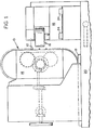
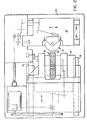
- Figures 1 and 2 illustrate the type of metalworking apparatus contemplated by the present invention.
- the illustrated apparatus is intended for gear manufacturing applications and includes an endless chain 10 made up of a series of articulated links for carrying stock removing tools 12.
- the stock removing tools 12 may be in the form of cutting or grinding tools and may be arranged in one or more rows around the entire circumference of the endless chain 10.
- Figure 1 shows the endless chain mounted in a vertical orientation around a housing 14 for being advanced toward and away from one or more workpieces 16 (workpieces may be manufactured one at a time or may be stacked and manufactured in multiple numbers). Movement of the housing 14 takes place on ways 18 carried on a base 20 of the machine.
- the workpieces 16 are removably mounted on a spindle carried in a housing 22.
- the housing 22 is mounted on ways 24, and known means are provided for translating the housing 22 and its retained workpieces 16 relative to the stock removing tools 12.
- the endless chain may be arranged in a horizontal orientation rather than the vertical one which is shown.
- Loading and unloading devices may be provided for moving workpieces into and out of the work station area, and it would be possible to provide for translation of the endless chain itself relative to a fixed position of the workpieces, if desired.
- known means are provided for tilting the housing 14 and its contained endless chain 10 for setting a helix angle for the manufacture of helical gears.
- Figure 3 illustrates structural details of the improved endless chain of this invention, as seen in a cross section which includes the work zone area where stock removal tools of the endless chain are engaging one or more workpieces (the portion of the chain which is in the work zone is that portion appearing to the right of the Figure 3 view).
- the individual links of the endless chain are pressed into firm contact with a supporting surface made up of two rows of rollers 30 (see also Figure 4) carried in a bed portion of the housing 14.
- Firm contact with the supporting surface is attained through the use of gib means 32 for pressing against a first set of rollers 34 carried by each link of the endless chain.
- the gib means 32 comprise a pair of parallel members fastened along opposite edges of the endless chain so as to overlap and contact the first set of rollers 34 only in the work zone area.
- the first set of rollers 34 are mounted for rotation on two separate shafts 36 carried on a common axis of each link of the endless chain, and thus, the entire link body is pressed into contact with the supporting rollers 30 when the rollers 34 advance beneath the parallel gib means 32 in the work zone portion of the travel of the endless chain.
- Figure 3 also shows the cross- sectional shape of each link as including a bottom bearing surface 35 for contacting the supporting rollers 30.
- a depending portion 37 of each link is shaped to contact rollers 39 which function to prevent side-to-side motion of the chain as it moves through the work zone.
- each link of the endless chain is provided with a second set of rollers 40 for supporting and guiding the individual links when they are out of the work zone portion of their travel.
- the second set of rollers are mounted for rotation on the same shafts 36 that carry the first set of rollers 34.
- the two sets of rollers for each link are mounted on a common axis and can rotate relative to each other as well as relative to the shafts 36 upon which they are mounted.
- the first set of rollers 34 and the second set of rollers 40 have separate functions inasmuch as the rollers 34 of the first set are engaged only when they are passing through the work zone area of the machine, while the rollers 40 engage guide surfaces provided in the housing 14 only when they are out of the work zone portion of the chain travel. Also, the separate sets of rollers rotate in opposite directions from each other. By shifting supporting functions from one set of rollers to another, it is possible to avoid the problem of a single set of rollers for each link having to reverse rotation as they enter or exit from the work zone area of the machine as a result of their contact with the gibs 32.
- each link advances through the work zone portion of the machine and then its rollers 34 move out of contact with the gib means 32 as its rollers 40 engage a guide surface 42.
- the guide surface 42 extends around both ends and along the back side of the chain housing.
- the guide surface 42 comprises a hardened rail, or similar structure which is shaped to guide the chain around the ends of the chain housing where the individual links must follow a curved path in order to provide for a return of the chain back to its starting point. It has been found that the curved path portion of the chain travel is very important and that the curve of the path should be non-circular in order to accommodate the articulated making up the endless chain.
- the non-circular path is designed to assure constant velocity of the chain as it advances around the entire housing.
- rollers 40 As the rollers 40 are exiting from the work zone area of the machine, they make contact with the guide surfaces 42 provided on each side of the chain housing. As contact is made, the rollers 40 start rotating. It is desirable, in certain applications, to optionally provide for a means for initiating rotation of these rollers 40 before full engagement with the hardened guide surfaces 42 is achieved. This can be done in the manner shown in Figure 5 wherein a strip of softer material 44 (such as a softer metal or even a suitable plastic material) is provided for making initial contact with the rollers 40 before they are in full contact with the very hard surfaces of the guide surfaces 42.
- a strip of softer material 44 such as a softer metal or even a suitable plastic material
- the strip of softer material 44 may be shaped to provide for diminishing contact with the roller 40 as the roller advances out of the work zone area and into full contact with the guide surface 42.
- a similar means for initiating rotation may be provided on the roller-engaging surfaces of the gib means 32, at the entry end of the work zone area, for initiating the rollers 34 as they enter the work zone.
- the invention provides for dual bearing means, in the form of two separate sets of rollers, carried by an endless chain for making separate contacts with gib means and guiding surfaces, respectively, as the endless chain travels around a housing.
Landscapes
- Engineering & Computer Science (AREA)
- Mechanical Engineering (AREA)
- Chain Conveyers (AREA)
Abstract
Description
- It is known in the art of broaching to provide for machines which utilize an endless chain for carrying a series of tools into contact with one or more workpieces. Typically, the endless chain is assembled from a plurality of articulated links, and the machine includes a housing for supporting the assembled endless chain and for defining a path of travel passing through a work zone where stock removal tools, carried by the articulated links, can engage the work as the endless chain is driven through the work zone. Examples of early machine designs of this type for producing spiral and helical gears are disclosed in U.S. patents 1,468,393; 1,469,602; 2,475,690; 2,692,537; and 2,749,804.
- Machines utilizing an endless chain for carrying tools offer a potential for very high speed production of whatever shape of workpiece is being formed by the tools. In fact, in the case of gear production, it is contemplated that stacks of gear blanks may be worked simultaneously with machinery of this type, rather than one at a time as has been the case with many other types of gear forming machines. However, the requirements for gear manufacture are far more severe than those for other forms of broaching, and therefore, machines of the endless chain type have not been, as far as I know, commercially acceptable for high production gear manufacturing needs up to this time. The forming of gear tooth profiles on a work blank requires precise control of an engagement between a workpiece and each cutting tool making contact with the workpiece. This requirement demands, in turn, a very rigid machine which maintains precise placement of both workpiece and tool under a working load and for a sustained operation of the machine. Since an endless chain is by its very nature not as rigid as other forms of tool-holding equipment, it has been a problem in this art to design and manufacture an endless chain type of machine having the capability of high production manufacture of precision gears.
- In copending European Application 79900841.2 (Publication Number WO 80/00319), which falls within the terms of Article 54(3) EPC we describe an improved type of endless chain apparatus in which the endless chain was firmly supported and carefully guided in its advancement through the critical work zone portion of its path of travel. This was partially accomplished by providing a supporting surface in the bed of the chain housing for firmly supporting the endless chain as its links were driven through the work zone area. In addition, gib means were carried adjacent the work zone for overlapping and pressing the endless chain into firm contact with the supporting surface, and this was done through a contact of the gib means with a pair of rollers carried by each link of the endless chain. As the endless chain entered the work zone portion of its travel, the rollers associated with the link were pressed toward the supporting surface of the chain housing by their rolling contact with the overlapping gib means carried along each edge of the work zone. This action, in turn, pressed the entire link toward the supporting surface in the bed of the chain housing. As each link advanced out of the work zone, its rollers became disengaged from the gib means and shifted their contact to guide surfaces provided throughout the remainder of the path of travel of the endless chain. This shifting from the gib means to the separate guide surfaces required a reversal of rotation of the pair of rollers associated with each link. Although such reversal in rotation is acceptable for many uses of this type of machine, there is a potential problem of unwanted wear taking place between the rollers and the guide surface which they contact in their course of travel from the work zone through the remainder of the chain housing.
- In the prior art, U.S.-A-2838980 shows an endless chain machine wherein rollers are borne on the chain for guiding it outside the work zone; but within the work zone those rollers are ineffective because gib means are used to press the links of the chain against a support surface, both the gib means and the support surface being plain bearings.
- In order to overcome any problems that may be associated with the guiding rollers of an endless chain, the present invention provides for two separate sets of rollers carried by the links of the endless chain for separately contacting the gib means (in the work zone) and the guiding surfaces (out of the work zone). The first set of rollers is carried in positions for contacting only the gib means as the endless chain is pressed into firm contact with the supporting surface of the chain housing in the work zone area of the machine. These rollers normally rotate only in the direction required for rolling contact with the gib means for advancement through the work zone. The second set of rollers is carried in positions which are out of contact with the gib means but which make rolling contact with the guide surfaces of the machine for all of the path of travel of the chain outside of the work zone area. The second set of rollers rotates only in a direction required for rolling engagement with the guide surfaces. Thus, the two sets of rollers can rotate in opposite directions at different times in the course of travel of the chain throughout its entire path of travel, and there is no requirement for a reversal of rotation of either set of rollers in whatever contact is being made with either the gib means or the guide surfaces of the machine. This provides for better control and support of the endless chain throughout its travel and eliminates the potential for unwanted wear of moving components which might otherwise be required to change direction of rotation very rapidly during the course of travel of the endless chain.
- In accordance with a specific embodiment of the invention, each link making up the endless chain assembly is provided with a first pair of rollers mounted on opposite sides of the link for making rolling contact only with gib means associated with the apparatus. In addition, a second pair of rollers is mounted on opposite sides of the link for making rolling contact only with the guide surfaces associated with the apparatus. The first and second pairs of rollers are mounted on a common axis provided by separate shafts carried on opposite sides of the link for supporting the rollers. Each separate shaft supports one roller of the first pair and one roller of the second pair in a side-by-side relationship.
- In order to further improve the rolling contact between the guiding rollers of the endless chain and the structures with which they make contact, there is optionally provided a means for initiating the rotation of the second set of rollers as the rollers leave the work zone area of the machine and before they make a full load bearing contact with the guide surfaces provided in the remainder of the machine. The means for initiating rotation comprises strips of relatively soft or resilient material which make initial contact with the rollers for the purpose of imparting a rotational moment thereto without engaging the rollers in a full load-bearing contact with the harder material of the guide surfaces which they ultimately contact. The softer material may comprise a strip of plastic or soft metal, and the strip may be of a configuration which provides for a diminishing contact between the roller and the strip as the roller advances toward a full contact with an associated guide surface.
- These and other features and advantages of the present invention will become apparent in the more detailed discussion which follows, and in that discussion reference will be made to the accompanying drawings as briefly described below.
- Figure 1 is a side elevational view of the type of apparatus being improved upon by the present invention;
- Figure 2 is a top plain view of the same apparatus shown in Figure 1;
- Figure 3 is a cross sectional view, in greatly enlarged scale, of a section of an endless chain and its associated structures as seen on line .3-3 of Figure 6;
- Figure 4 is a plan view of a portion of the endless chain of Figure 3 as seen on line 4-4 of Figure 6;
- Figure 5 is an enlarged view of just a portion of the assembly shown in Figure 4; and
- Figure 6 is a side view, in section, of a portion of the endless chain, as seen on line 6-6 of Figure 4.
- Figures 1 and 2 illustrate the type of metalworking apparatus contemplated by the present invention. The illustrated apparatus is intended for gear manufacturing applications and includes an
endless chain 10 made up of a series of articulated links for carryingstock removing tools 12. Thestock removing tools 12 may be in the form of cutting or grinding tools and may be arranged in one or more rows around the entire circumference of theendless chain 10. Figure 1 shows the endless chain mounted in a vertical orientation around ahousing 14 for being advanced toward and away from one or more workpieces 16 (workpieces may be manufactured one at a time or may be stacked and manufactured in multiple numbers). Movement of thehousing 14 takes place onways 18 carried on abase 20 of the machine. At the work station end of the machine, theworkpieces 16 are removably mounted on a spindle carried in a housing 22. The housing 22 is mounted onways 24, and known means are provided for translating the housing 22 and its retainedworkpieces 16 relative to thestock removing tools 12. - Details of the apparatus may vary widely in accordance with known design features for such machines. For example, the endless chain may be arranged in a horizontal orientation rather than the vertical one which is shown. Loading and unloading devices may be provided for moving workpieces into and out of the work station area, and it would be possible to provide for translation of the endless chain itself relative to a fixed position of the workpieces, if desired. In addition, known means are provided for tilting the
housing 14 and its containedendless chain 10 for setting a helix angle for the manufacture of helical gears. - Figure 3 illustrates structural details of the improved endless chain of this invention, as seen in a cross section which includes the work zone area where stock removal tools of the endless chain are engaging one or more workpieces (the portion of the chain which is in the work zone is that portion appearing to the right of the Figure 3 view). In the work zone portion of its travel, the individual links of the endless chain are pressed into firm contact with a supporting surface made up of two rows of rollers 30 (see also Figure 4) carried in a bed portion of the
housing 14. Firm contact with the supporting surface is attained through the use of gib means 32 for pressing against a first set ofrollers 34 carried by each link of the endless chain. As further illustrated in Figure 4, the gib means 32 comprise a pair of parallel members fastened along opposite edges of the endless chain so as to overlap and contact the first set ofrollers 34 only in the work zone area. The first set ofrollers 34 are mounted for rotation on twoseparate shafts 36 carried on a common axis of each link of the endless chain, and thus, the entire link body is pressed into contact with the supportingrollers 30 when therollers 34 advance beneath the parallel gib means 32 in the work zone portion of the travel of the endless chain. Figure 3 also shows the cross- sectional shape of each link as including abottom bearing surface 35 for contacting the supportingrollers 30. In addition a dependingportion 37 of each link is shaped to contactrollers 39 which function to prevent side-to-side motion of the chain as it moves through the work zone. The description so far is similar to those included in our copending patent applications (identified above), and reference can be made to those applications for a more complete understanding of other structures shown in Figure 3 which are not relevant to an understanding of the specific invention of this application. - In accordance with the present invention, each link of the endless chain is provided with a second set of
rollers 40 for supporting and guiding the individual links when they are out of the work zone portion of their travel. In the illustrated embodiment, the second set of rollers are mounted for rotation on thesame shafts 36 that carry the first set ofrollers 34. Thus, the two sets of rollers for each link are mounted on a common axis and can rotate relative to each other as well as relative to theshafts 36 upon which they are mounted. The first set ofrollers 34 and the second set ofrollers 40 have separate functions inasmuch as therollers 34 of the first set are engaged only when they are passing through the work zone area of the machine, while therollers 40 engage guide surfaces provided in thehousing 14 only when they are out of the work zone portion of the chain travel. Also, the separate sets of rollers rotate in opposite directions from each other. By shifting supporting functions from one set of rollers to another, it is possible to avoid the problem of a single set of rollers for each link having to reverse rotation as they enter or exit from the work zone area of the machine as a result of their contact with thegibs 32. As shown in Figures 4, 5 and 6, each link advances through the work zone portion of the machine and then itsrollers 34 move out of contact with the gib means 32 as itsrollers 40 engage aguide surface 42. Theguide surface 42 extends around both ends and along the back side of the chain housing. Theguide surface 42 comprises a hardened rail, or similar structure which is shaped to guide the chain around the ends of the chain housing where the individual links must follow a curved path in order to provide for a return of the chain back to its starting point. It has been found that the curved path portion of the chain travel is very important and that the curve of the path should be non-circular in order to accommodate the articulated making up the endless chain. The non-circular path is designed to assure constant velocity of the chain as it advances around the entire housing. - As the
rollers 40 are exiting from the work zone area of the machine, they make contact with the guide surfaces 42 provided on each side of the chain housing. As contact is made, therollers 40 start rotating. It is desirable, in certain applications, to optionally provide for a means for initiating rotation of theserollers 40 before full engagement with the hardened guide surfaces 42 is achieved. This can be done in the manner shown in Figure 5 wherein a strip of softer material 44 (such as a softer metal or even a suitable plastic material) is provided for making initial contact with therollers 40 before they are in full contact with the very hard surfaces of the guide surfaces 42. As shown in Figure 5, the strip ofsofter material 44 may be shaped to provide for diminishing contact with theroller 40 as the roller advances out of the work zone area and into full contact with theguide surface 42. A similar means for initiating rotation may be provided on the roller-engaging surfaces of the gib means 32, at the entry end of the work zone area, for initiating therollers 34 as they enter the work zone. - Thus, the invention provides for dual bearing means, in the form of two separate sets of rollers, carried by an endless chain for making separate contacts with gib means and guiding surfaces, respectively, as the endless chain travels around a housing. Although the invention has been described and discussed with reference to a specific embodiment only, equivalent designs are intended to be included within the scope of the claims.
Claims (8)
Applications Claiming Priority (2)
| Application Number | Priority Date | Filing Date | Title |
|---|---|---|---|
| US950908 | 1978-10-12 | ||
| US05/950,908 US4198185A (en) | 1978-10-12 | 1978-10-12 | Metalworking apparatus having improved means for supporting and guiding an endless chain |
Publications (3)
| Publication Number | Publication Date |
|---|---|
| EP0020400A1 EP0020400A1 (en) | 1981-01-07 |
| EP0020400A4 EP0020400A4 (en) | 1981-02-20 |
| EP0020400B1 true EP0020400B1 (en) | 1983-03-30 |
Family
ID=25491010
Family Applications (1)
| Application Number | Title | Priority Date | Filing Date |
|---|---|---|---|
| EP79901116A Expired EP0020400B1 (en) | 1978-10-12 | 1980-05-07 | Support and guide for endless chain of metalworking apparatus |
Country Status (6)
| Country | Link |
|---|---|
| US (1) | US4198185A (en) |
| EP (1) | EP0020400B1 (en) |
| JP (1) | JPS55500005U (en) |
| CA (1) | CA1092868A (en) |
| DE (1) | DE2965086D1 (en) |
| WO (1) | WO1980000806A1 (en) |
Family Cites Families (3)
| Publication number | Priority date | Publication date | Assignee | Title |
|---|---|---|---|---|
| US2080464A (en) * | 1935-04-17 | 1937-05-18 | Foote Burt Co | Metal cutting machine |
| US2838980A (en) * | 1956-10-03 | 1958-06-17 | Foote Burt Co | Continuous broaching machines |
| SU380404A1 (en) * | 1971-07-06 | 1973-05-15 | CONTINUOUS PROFESSIONAL MACHINE |
-
1978
- 1978-10-12 US US05/950,908 patent/US4198185A/en not_active Expired - Lifetime
-
1979
- 1979-02-16 JP JP1980600005U patent/JPS55500005U/ja active Pending
- 1979-02-16 DE DE7979901116T patent/DE2965086D1/en not_active Expired
- 1979-02-16 WO PCT/US1979/000093 patent/WO1980000806A1/en not_active Ceased
- 1979-02-28 CA CA322,504A patent/CA1092868A/en not_active Expired
-
1980
- 1980-05-07 EP EP79901116A patent/EP0020400B1/en not_active Expired
Also Published As
| Publication number | Publication date |
|---|---|
| EP0020400A1 (en) | 1981-01-07 |
| CA1092868A (en) | 1981-01-06 |
| US4198185A (en) | 1980-04-15 |
| DE2965086D1 (en) | 1983-05-05 |
| EP0020400A4 (en) | 1981-02-20 |
| WO1980000806A1 (en) | 1980-05-01 |
| JPS55500005U (en) | 1980-10-16 |
Similar Documents
| Publication | Publication Date | Title |
|---|---|---|
| US3897705A (en) | Device for slitting sheet material | |
| JPH0343017B2 (en) | ||
| CH668574A5 (en) | NC VERTICAL GRINDING MACHINE. | |
| US4363526A (en) | Linear motion ball bearing unit | |
| CN212552225U (en) | Plasma cutting equipment with polishing function | |
| US4198185A (en) | Metalworking apparatus having improved means for supporting and guiding an endless chain | |
| US4012829A (en) | Shaping-and-cutting broach | |
| KR101771048B1 (en) | Thread rolling machine and thread rolling method | |
| CA1095762A (en) | Drive train for gear manufacturing machine and method of use | |
| EP0016130B1 (en) | Endless chain apparatus for forming gears | |
| US2993417A (en) | Method and apparatus for machining the ends of the teeth of gear wheels and similar workpieces | |
| US3510995A (en) | Method for rectifying objects such as dies of reducing rolling machines | |
| US4036105A (en) | Machine for edge forming of sheets for welding | |
| DE674787C (en) | Process for removing the rolled skin from metal strips | |
| JP5195788B2 (en) | Processing method of linear motion guide rail | |
| SU48112A1 (en) | Machine for the manufacture of gears by hot rolling | |
| CA1127897A (en) | Controllable tooling for gear cutting machine | |
| SU1225661A1 (en) | Forging rolls | |
| DE4101881A1 (en) | Rotary tool for cutting grooves in roller cage | |
| JP2004028201A (en) | Linear guide rail and its machining method | |
| SU963745A1 (en) | Disc shaver | |
| EP0016142B1 (en) | Endless chain apparatus for forming gears | |
| SU806303A1 (en) | Method of working toother gears by shaver | |
| CN113770455A (en) | Double-sided flying wing relieving equipment and feeding device thereof | |
| DE2139844A1 (en) | ROUNDING MACHINE FOR BREAST OF GEAR |
Legal Events
| Date | Code | Title | Description |
|---|---|---|---|
| PUAI | Public reference made under article 153(3) epc to a published international application that has entered the european phase |
Free format text: ORIGINAL CODE: 0009012 |
|
| 17P | Request for examination filed |
Effective date: 19800923 |
|
| AK | Designated contracting states |
Designated state(s): CH DE FR GB SE |
|
| GRAA | (expected) grant |
Free format text: ORIGINAL CODE: 0009210 |
|
| AK | Designated contracting states |
Designated state(s): CH DE FR GB |
|
| REF | Corresponds to: |
Ref document number: 2965086 Country of ref document: DE Date of ref document: 19830505 |
|
| ET | Fr: translation filed | ||
| PGFP | Annual fee paid to national office [announced via postgrant information from national office to epo] |
Ref country code: FR Payment date: 19840203 Year of fee payment: 6 |
|
| PGFP | Annual fee paid to national office [announced via postgrant information from national office to epo] |
Ref country code: CH Payment date: 19840409 Year of fee payment: 6 |
|
| PGFP | Annual fee paid to national office [announced via postgrant information from national office to epo] |
Ref country code: DE Payment date: 19850320 Year of fee payment: 7 |
|
| PG25 | Lapsed in a contracting state [announced via postgrant information from national office to epo] |
Ref country code: CH Effective date: 19860228 |
|
| GBPC | Gb: european patent ceased through non-payment of renewal fee | ||
| PG25 | Lapsed in a contracting state [announced via postgrant information from national office to epo] |
Ref country code: FR Free format text: LAPSE BECAUSE OF NON-PAYMENT OF DUE FEES Effective date: 19861031 |
|
| REG | Reference to a national code |
Ref country code: CH Ref legal event code: PL |
|
| PG25 | Lapsed in a contracting state [announced via postgrant information from national office to epo] |
Ref country code: DE Effective date: 19861101 |
|
| REG | Reference to a national code |
Ref country code: FR Ref legal event code: ST |
|
| PG25 | Lapsed in a contracting state [announced via postgrant information from national office to epo] |
Ref country code: GB Effective date: 19881118 |
|
| PLBE | No opposition filed within time limit |
Free format text: ORIGINAL CODE: 0009261 |
|
| STAA | Information on the status of an ep patent application or granted ep patent |
Free format text: STATUS: NO OPPOSITION FILED WITHIN TIME LIMIT |