EP0020152B1 - Anchor shank - Google Patents
Anchor shank Download PDFInfo
- Publication number
- EP0020152B1 EP0020152B1 EP80301793A EP80301793A EP0020152B1 EP 0020152 B1 EP0020152 B1 EP 0020152B1 EP 80301793 A EP80301793 A EP 80301793A EP 80301793 A EP80301793 A EP 80301793A EP 0020152 B1 EP0020152 B1 EP 0020152B1
- Authority
- EP
- European Patent Office
- Prior art keywords
- anchor
- shank
- fluke
- members
- elongate
- Prior art date
- Legal status (The legal status is an assumption and is not a legal conclusion. Google has not performed a legal analysis and makes no representation as to the accuracy of the status listed.)
- Expired
Links
Images
Classifications
-
- B—PERFORMING OPERATIONS; TRANSPORTING
- B63—SHIPS OR OTHER WATERBORNE VESSELS; RELATED EQUIPMENT
- B63B—SHIPS OR OTHER WATERBORNE VESSELS; EQUIPMENT FOR SHIPPING
- B63B21/00—Tying-up; Shifting, towing, or pushing equipment; Anchoring
- B63B21/24—Anchors
-
- B—PERFORMING OPERATIONS; TRANSPORTING
- B63—SHIPS OR OTHER WATERBORNE VESSELS; RELATED EQUIPMENT
- B63B—SHIPS OR OTHER WATERBORNE VESSELS; EQUIPMENT FOR SHIPPING
- B63B21/00—Tying-up; Shifting, towing, or pushing equipment; Anchoring
- B63B21/24—Anchors
- B63B21/26—Anchors securing to bed
- B63B2021/262—Anchors securing to bed by drag embedment
Definitions
- This invention relates to anchors including fluke and a shank adapted at one end to be attached to an anchor line and at the other end to be attached to the fluke, the shank comprising at least two transversely spaced elongate plate members which extend generally in the fore and after direction, said elongate plate members including leading and trailing edges and being connected by at least one transverse plate member located between said shank ends and having at least a portion inclined to present a positive angle of attack to the sea bed soil, a plurality of rearwardly directed open-ended passages being provided between the elongate plate members.
- the shank of an anchor is a member connecting the cable attachment point of an anchor with its fluke. This member has the function of maintaining the fluke at an inclination to the surface of a mooring bed on which the anchor is cast such that penetration therethrough and burial into the bed is achieved when a substantially horizontal pull on the anchor is applied by the cable.
- the shank is required to resist bending moment applied to it in a vertical plane by partial or complete penetration of the fluke in the mooring bed soil or by point loading of the fluke when engaging on rocks. It is also required to resist bending moment applied in a horizontal plane by veering of the anchor cable following engagement of the anchor fluke with the mooring bed.
- the shank comprised a pair of spaced plates with the forward ends arranged to receive a shackle bolt for the anchor line, but this structure alone did not provide adequate resistance to lateral bending.
- a lateral web plate may be located between the spaced shank plates in the manner of an H beam but this greatly increases the resistance to soil penetration of the anchor.
- An anchor according to the precharacterising part of claim 1 is known (see French Patent FR-A-2082722) for use in sea beds of very soft mud, this anchor comprising a fluke in the form of a transversely arranged bulldozer shovel blade, and a horizontal balancing frame attached to the shovel blade and serving for attachment to the anchor cable, the balancing frame comprising transversely spaced longitudinal plate members joined by transverse plates which plates were inclined to present burial surfaces. Further horizontal plating was provided on the top of the balancing frame to stabilise the burying depth at an optimum value, this plating serving additionally to strengthen the frame.
- An object of the present invention is to provide an anchor shank having high bending moment resistance, low soil penetration resistance, and a capability of contributing to the burial forces developed by the anchor while interacting with the mooring bed soil.
- the present invention is distinguished from prior anchors by arranging the shank to be of cranked form having a longer leg adapted for attachment to the anchor line and a shorter leg attached to the anchor fluke by having the rearwardly directed open-ended passages of the shank of substantially non-convergent form with the cross-sectional area of their outlets substantially equal to or greater than the cross-sectional area of their inlets to permit substantially unobstructed soil flow through the shank, and by having one of said open-ended passages located adjacent the fluke and in the shorter leg of the cranked shank to permit escape of a rearward flow of soil between the trailing edges of the shorter leg.
- any substantial increase of resistance to soil penetration by the shank can be avoided thereby enabling deep burial of the anchor, while allowing high bending moment resistance to be present in the shank, and additionally allowing the plate member arrangement to contribute to the burial forces generated by the anchor by acting as an auxiliary fluke.
- said plate member occupies a substantially mid-location between the shank ends.
- the transverse plate is inclined at an acute angle to the fluke in the range 0° to 40°, and preferably 5° to 25°.
- each transverse plate member Preferably a plurality of transverse plate members are provided.
- the cross-sectional area bounded by the elongate members and successive transverse plate members increases rearwardly to provide divergent passages to soil flowing between the longitudinal members.
- the inclination of each transverse plate member to the fluke centre line decreases with remoteness from the anchor line attachment end of the shank to provide said divergent passages.
- the shank is of L-shaped form, and a transverse plate member is located in the shorter fluke attached leg of the shank; and preferably said plate member is located adjacent the elbow of the L-shaped shank.
- the longitudinal shank members can be arranged to extend in parallel, but preferably forward portions of the members converge and form a lug for receiving the anchor cable shackle bolt.
- the converging portions make backwardly inclined line intercepts with the parallel longitudinal members whereby the converging portions define burial surfaces.
- the shank can be detachably secured to the fluke.
- the above shank according to the present invention can be applied to a wide variety of fluke forms.
- it is very satisfactorily used in an anchor according to the applicants U.K. patents GB-A-1356259 and GB-A-1513453.
- the present shank permits a considerable reduction in weight of the shank, so that for a given anchor size, the fluke weight (and size) can be very considerably increased which will give a substantial increase in holding power.
- an anchor shank 1 of an anchor 2 is attached to a fluke 3 and comprises two L-shaped plates 4, 5 generally equally spaced one at each side of a central plane of symmetry S-S of the anchor 2 and connected together by inclined plates 6, 7, 8 each having approximately half of the thickness of the L-shaped plates 4, 5.
- Each L-shaped plate 4,5 has a first leg 9 adapted to be joined at its lower end to fluke 3 and extending from the fluke surface adjacent a central symmetry plane to an elbow 10 spaced from and above the fluke surface.
- the L-shaped plates 4, 5 are spaced apart approximately twelve times their thickness and have maximum depth of section at the elbow 10 of approximately twenty-two times their thickness.
- a second leg 11 extends at an angle to its bottom edge of 20° relative to a line intercept of the fluke upper surface with the symmetry plane and forwardly from the elbow 10 to a free end or lug 12 bored with a hole 13 to provide aligned bores suitable for receiving one end of a bolt (not shown) to a shackle for attachment of a chain, cable or rope to the ends 12 of the shank.
- the inclined plate 6 is located below the elbow 10 with its forward edge spaced approximately 39 times its thickness from the fluke in a direction normal to plate 6, being inclined at an angle of 10° i.e. with positive burial angle to the line intercept of the fluke upper surface with the symmetry plane of the anchor while extending substantially fully between forward and rear edges of each first leg 9 of plates 4, 5.
- the inclined plate 7 is located above and forward of plate 6 and is spaced from the front edge of plate 6 approximately 42 times its thickness in a direction normal to plate 6, being inclined at 14° to the line intercept of the fluke upper surface with the symmetry plane while extending fully between lower and upper edges of each second leg 11 of plates 4, 5.
- the inclined plate 8 is located forward of plate 7 and is spaced approximately 30 times its thickness from the forward edge of plate 7 in a direction normal to plate 7, being inclined at 18° to the line intercept of the fluke upper surface with the symmetry plane of the anchor.
- the plates 6, 7, 8 can include stiffener ribs 40.
- the legs 11 include forward flat converging portions 41 which are bent to provide parallel front lug portions 12, and the portions 41 are shaped to provide burial surfaces, the portions 41 providing backwardly inclined line intercepts 42 with the legs 11 and the symmetry plane S-S. As can be seen in Figure 1, these intercepts 42 are inclined similarly as the plate 8.
- the shank 1 is removably secured to the fluke 3 by legs 9 being removably attached by bolts 43 to upstanding flanges 44 on the fluke 3.
- bolts 43 can be repositioned to permit the fluke angle to be increased for soft bottoms as indicated in Figure 1.
- the detachability of the shank facilitates the storage and transportability of the anchor, particularly for large size anchors, the plates 4, 5, include leading edges 45 of knife- edge form.
- the geometry of the fluke 3 including side portions 3a, 3b satisfies the applicant's U.K. patents Nos. 1356259 and 1513453, and as best seen in Figure 3 the central fluke portion 3 is substantially flat with sides 3a, 3b, of curved form.
- the anchor which for example can be of 250 Kg weight or greater, is conveniently made of a steel fabrication construction.
- the fluke 3 is of hollow double skin form.
- the bottom skin comprises plate segment 46 with a nose portion 47 of stacked plate form, while the upper skin comprises side plate segments 48, 49 and flat central plate 50.
- the hollow fluke formation is closed by back plates 51.
- the flanges 44 extend through slots (not shown) in top plate 50 and rest on the bottom skin to which they are welded.
- the various plate segments are joined by welding.
- the plates of portions 3a, 3b can be placed in curved form by a series of straight line bends, and these portions provide conical working surfaces with a cone apex located rearwardly. More particularly, the surfaces of part segments 48, 49 have different semi-cone angles; and with reference to Figure 3, the segment 48 can have a semi-cone angle of approximately 25° while the outer segment 49 is of more splayed form with a semi-cone angle of approximately 42°. This feature facilitates the rolling self-orientating and dynamic stabilising characteristics of the anchor as explained in U.K. patent No. 1356259.
- the hollow portions of the fluke can be filled with suitable material e.g. concrete or resin to strengthen the structure and also to vary the weight of the anchor as desired.
- suitable material e.g. concrete or resin to strengthen the structure and also to vary the weight of the anchor as desired.
- the webs 6-8 take the majority of the shear load enabling the plate members 4, 5 to be of relatively thin form; for example in a 6t ton single-member shank anchor, the shank plate would have a width of 8 ins. while with the present double-plate shank the plates 4, 5 could be each 2 in. thick. Consequently, the shank can be considerably lighter than previously and more weight can be transferred to the fluke which is advantageous performance wise.
- the central portion 3 is of substantially greater size than previously due to the added area enclosed between the planes of plates 4, 5.
- the plates 4, 5 are arranged to be completely parallel.
- the spaced-parallel plate form of the shank facilitates the provision of a plurality of aligned hole pairs in the forward part of the shank, for reception of the anchor line shackle bolt, so enabling variation in the position of the bolt. Variation in shackle bolt position alters the attack angle of the fluke; for example a more rearward position provides a greater fluke attack angle and this is more satisfactory for use in a mud bed.
- the plate 6 can have a hole 52 facilitating the fitting of an anchor break-out line to the anchor.
- the above anchors will have a very high per unit weight holding power and will also incorporate the stabilising characteristics of the anchors of U.K. patent 1356259: the anchors can therefore be satisfactorily used for mooring vessels or installations in severe offshore conditions.
- an L-shaped articulated anchor shank 14 of an anchor 15 is attached to a fluke 16 and comprises a downwardly extending first leg 17 and a forwardly extending second leg 18 joined together pivotably by a pin-jointed elbow 19 spaced from and above the fluke surface.
- Each leg 17 and 18 comprises elongate plates 20, 21, and 22, 23 respectively spaced one at each side of a symmetry plane of the anchor and connected by inclined plates 24, 25, 26 extending over the full depth of the elongate plates and inclined respectively at 7°, 29°, and 30° to the line intercept of the fluke upper surface with the symmetry plane and with plate 24 located midway on leg 17 and plates 25, 26 to trisect leg 18.
- the second leg 18 extends at an angle to its bottom edge of 28° relative to a line intercept of the fluke upper surface with the symmetry plane and forwardly from the articulated elbow 19 to a free end 27 bored with coaxial holes 28, 29 suitable for receiving the ends of a bolt of a shackle for attachment of a chain, cable or rope to the end 27 of the shank.
- each passageway 60 through the shank between plates 7/8 (25/26) and 6/7 and 6/30 diverges rearwards, with outlet 62 of the passage having a cross sectional area substantially equal to or greater than that of passage inlet 61.
- the open construction of the shank permits soil to pass easily through the structure and so gives low penetration resistance during burial of the anchor.
- the divergent passages within the shank accommodate those soils which expand during shearing so that the tendency of the expanded soil to jam within the passages is avoided thus maintaining a low resistance to penetration of the shank even in dense sands.
- Soil impinging on the inclined plates inside the shank develops a thrust with a downwards component which adds to that produced by the anchor fluke and so assists burial of the anchor.
Description
- This invention relates to anchors including fluke and a shank adapted at one end to be attached to an anchor line and at the other end to be attached to the fluke, the shank comprising at least two transversely spaced elongate plate members which extend generally in the fore and after direction, said elongate plate members including leading and trailing edges and being connected by at least one transverse plate member located between said shank ends and having at least a portion inclined to present a positive angle of attack to the sea bed soil, a plurality of rearwardly directed open-ended passages being provided between the elongate plate members.
- The shank of an anchor is a member connecting the cable attachment point of an anchor with its fluke. This member has the function of maintaining the fluke at an inclination to the surface of a mooring bed on which the anchor is cast such that penetration therethrough and burial into the bed is achieved when a substantially horizontal pull on the anchor is applied by the cable. The shank is required to resist bending moment applied to it in a vertical plane by partial or complete penetration of the fluke in the mooring bed soil or by point loading of the fluke when engaging on rocks. It is also required to resist bending moment applied in a horizontal plane by veering of the anchor cable following engagement of the anchor fluke with the mooring bed. Provision of adequate bending moment resistance in the shank generally calls for deep sections in two transverse directions at right angles to each other and, consequently, a heavy shank which may well comprise two thirds of the total weight of the anchor and contribute considerably to the resistance of the anchor to penetration of the mooring bed without contributing to the burial forces developed by the anchor fluke. Anchors with shanks of this type are shown in U.K. patent specifications GB-A-694,976; GB-A-1,296,139; GB-A-1,356,259 and GB-A-1,496,510. In a previous modified shank form, the shank comprised a pair of spaced plates with the forward ends arranged to receive a shackle bolt for the anchor line, but this structure alone did not provide adequate resistance to lateral bending. To overcome this problem a lateral web plate may be located between the spaced shank plates in the manner of an H beam but this greatly increases the resistance to soil penetration of the anchor.
- An anchor according to the precharacterising part of claim 1 is known (see French Patent FR-A-2082722) for use in sea beds of very soft mud, this anchor comprising a fluke in the form of a transversely arranged bulldozer shovel blade, and a horizontal balancing frame attached to the shovel blade and serving for attachment to the anchor cable, the balancing frame comprising transversely spaced longitudinal plate members joined by transverse plates which plates were inclined to present burial surfaces. Further horizontal plating was provided on the top of the balancing frame to stabilise the burying depth at an optimum value, this plating serving additionally to strengthen the frame. The optimum burial requirement was influenced by the somewhat upright nature of the shovel blade, and the horizontal plating resulted in the cross-sectional area of the passage outlets in the frame being substantially less than the cross-sectional area of the passage inlets. This had the disadvantage of precluding substantially unobstructed flow of soil through the frame and in particular the upright blade prevented a rearward flow of soil from the frame passage adjacent the blade. Thus there would be decided disadvantages in using such a frame structure as a shank in general purpose anchors where deep burial is a requisite.
- An object of the present invention is to provide an anchor shank having high bending moment resistance, low soil penetration resistance, and a capability of contributing to the burial forces developed by the anchor while interacting with the mooring bed soil.
- The present invention is distinguished from prior anchors by arranging the shank to be of cranked form having a longer leg adapted for attachment to the anchor line and a shorter leg attached to the anchor fluke by having the rearwardly directed open-ended passages of the shank of substantially non-convergent form with the cross-sectional area of their outlets substantially equal to or greater than the cross-sectional area of their inlets to permit substantially unobstructed soil flow through the shank, and by having one of said open-ended passages located adjacent the fluke and in the shorter leg of the cranked shank to permit escape of a rearward flow of soil between the trailing edges of the shorter leg.
- By arranging the shank in the above described manner, any substantial increase of resistance to soil penetration by the shank can be avoided thereby enabling deep burial of the anchor, while allowing high bending moment resistance to be present in the shank, and additionally allowing the plate member arrangement to contribute to the burial forces generated by the anchor by acting as an auxiliary fluke.
- Preferably said plate member occupies a substantially mid-location between the shank ends.
- Preferably, the transverse plate is inclined at an acute angle to the fluke in the range 0° to 40°, and preferably 5° to 25°.
- Preferably a plurality of transverse plate members are provided. Preferably the cross-sectional area bounded by the elongate members and successive transverse plate members increases rearwardly to provide divergent passages to soil flowing between the longitudinal members. Preferably the inclination of each transverse plate member to the fluke centre line decreases with remoteness from the anchor line attachment end of the shank to provide said divergent passages.
- Preferably the shank is of L-shaped form, and a transverse plate member is located in the shorter fluke attached leg of the shank; and preferably said plate member is located adjacent the elbow of the L-shaped shank.
- The longitudinal shank members can be arranged to extend in parallel, but preferably forward portions of the members converge and form a lug for receiving the anchor cable shackle bolt. In a preferred arrangement the converging portions make backwardly inclined line intercepts with the parallel longitudinal members whereby the converging portions define burial surfaces. The shank can be detachably secured to the fluke.
- The above shank according to the present invention can be applied to a wide variety of fluke forms. In particular, it is very satisfactorily used in an anchor according to the applicants U.K. patents GB-A-1356259 and GB-A-1513453. The present shank permits a considerable reduction in weight of the shank, so that for a given anchor size, the fluke weight (and size) can be very considerably increased which will give a substantial increase in holding power.
- Embodiments of the invention will now be described, by way of example, with reference to the accompanying drawings in which:-
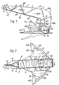
- Figure 1 is a side elevation of an anchor with a shank according to one embodiment of the present invention;
- Figure 2 is a plan view of the anchor of Figure 1;
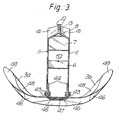
- Figure 3 is a front elevational view of the anchor of Figure 1;
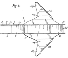
- Figure 4 shows a plan view of an anchor with a shank, according to a second embodiment of the present invention; and
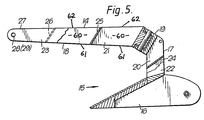
- Figure 5 shows in partially sectional side elevation the shank of the present invention applied in an anchor with a different fluke form.
- Referring to Figures 1, 2 and 3 an anchor shank 1 of an
anchor 2 is attached to afluke 3 and comprises two L-shaped plates anchor 2 and connected together byinclined plates shaped plates shaped plate fluke 3 and extending from the fluke surface adjacent a central symmetry plane to anelbow 10 spaced from and above the fluke surface. The L-shaped plates elbow 10 of approximately twenty-two times their thickness. A second leg 11 extends at an angle to its bottom edge of 20° relative to a line intercept of the fluke upper surface with the symmetry plane and forwardly from theelbow 10 to a free end orlug 12 bored with ahole 13 to provide aligned bores suitable for receiving one end of a bolt (not shown) to a shackle for attachment of a chain, cable or rope to theends 12 of the shank. - The inclined plate 6 is located below the
elbow 10 with its forward edge spaced approximately 39 times its thickness from the fluke in a direction normal to plate 6, being inclined at an angle of 10° i.e. with positive burial angle to the line intercept of the fluke upper surface with the symmetry plane of the anchor while extending substantially fully between forward and rear edges of each first leg 9 ofplates - The
inclined plate 7 is located above and forward of plate 6 and is spaced from the front edge of plate 6 approximately 42 times its thickness in a direction normal to plate 6, being inclined at 14° to the line intercept of the fluke upper surface with the symmetry plane while extending fully between lower and upper edges of each second leg 11 ofplates - The
inclined plate 8 is located forward ofplate 7 and is spaced approximately 30 times its thickness from the forward edge ofplate 7 in a direction normal toplate 7, being inclined at 18° to the line intercept of the fluke upper surface with the symmetry plane of the anchor. Theplates stiffener ribs 40. - The legs 11 include forward flat converging
portions 41 which are bent to provide parallelfront lug portions 12, and theportions 41 are shaped to provide burial surfaces, theportions 41 providing backwardlyinclined line intercepts 42 with the legs 11 and the symmetry plane S-S. As can be seen in Figure 1, theseintercepts 42 are inclined similarly as theplate 8. The shank 1 is removably secured to thefluke 3 by legs 9 being removably attached bybolts 43 to upstandingflanges 44 on thefluke 3. By virtue of holes 43A in both legs 9 andflanges 44 and holes 43B inflanges 44 only,bolts 43 can be repositioned to permit the fluke angle to be increased for soft bottoms as indicated in Figure 1. The detachability of the shank facilitates the storage and transportability of the anchor, particularly for large size anchors, theplates edges 45 of knife- edge form. - The geometry of the
fluke 3 includingside portions 3a, 3b satisfies the applicant's U.K. patents Nos. 1356259 and 1513453, and as best seen in Figure 3 thecentral fluke portion 3 is substantially flat withsides 3a, 3b, of curved form. The anchor which for example can be of 250 Kg weight or greater, is conveniently made of a steel fabrication construction. In particular, thefluke 3 is of hollow double skin form. The bottom skin comprisesplate segment 46 with anose portion 47 of stacked plate form, while the upper skin comprisesside plate segments central plate 50. The hollow fluke formation is closed byback plates 51. Theflanges 44 extend through slots (not shown) intop plate 50 and rest on the bottom skin to which they are welded. Additionally internal ribs could be provided in the hollow fluke structure. The various plate segments are joined by welding. The plates ofportions 3a, 3b can be placed in curved form by a series of straight line bends, and these portions provide conical working surfaces with a cone apex located rearwardly. More particularly, the surfaces ofpart segments segment 48 can have a semi-cone angle of approximately 25° while theouter segment 49 is of more splayed form with a semi-cone angle of approximately 42°. This feature facilitates the rolling self-orientating and dynamic stabilising characteristics of the anchor as explained in U.K. patent No. 1356259. - The hollow portions of the fluke can be filled with suitable material e.g. concrete or resin to strengthen the structure and also to vary the weight of the anchor as desired. In the present shank, the webs 6-8 take the majority of the shear load enabling the
plate members plates central portion 3 is of substantially greater size than previously due to the added area enclosed between the planes ofplates - In the emodiment shown in Figure 4, the
plates hole 52 facilitating the fitting of an anchor break-out line to the anchor. The above anchors will have a very high per unit weight holding power and will also incorporate the stabilising characteristics of the anchors of U.K. patent 1356259: the anchors can therefore be satisfactorily used for mooring vessels or installations in severe offshore conditions. - Referring now to Figure 5, an L-shaped articulated
anchor shank 14 of ananchor 15 is attached to afluke 16 and comprises a downwardly extendingfirst leg 17 and a forwardly extendingsecond leg 18 joined together pivotably by a pin-jointed elbow 19 spaced from and above the fluke surface. Eachleg elongate plates inclined plates plate 24 located midway onleg 17 andplates leg 18. - The
second leg 18 extends at an angle to its bottom edge of 28° relative to a line intercept of the fluke upper surface with the symmetry plane and forwardly from the articulated elbow 19 to afree end 27 bored withcoaxial holes end 27 of the shank. - In the above embodiments each
passageway 60 through the shank betweenplates 7/8 (25/26) and 6/7 and 6/30 diverges rearwards, withoutlet 62 of the passage having a cross sectional area substantially equal to or greater than that ofpassage inlet 61. - The open construction of the shank permits soil to pass easily through the structure and so gives low penetration resistance during burial of the anchor. The divergent passages within the shank accommodate those soils which expand during shearing so that the tendency of the expanded soil to jam within the passages is avoided thus maintaining a low resistance to penetration of the shank even in dense sands. Soil impinging on the inclined plates inside the shank develops a thrust with a downwards component which adds to that produced by the anchor fluke and so assists burial of the anchor.
- Modifications are of course possible. For example where the
plates transverse plates plates plates 6, 7 8 may form part of transverse hollow elements.
Claims (11)
Applications Claiming Priority (2)
| Application Number | Priority Date | Filing Date | Title |
|---|---|---|---|
| GB7919169 | 1979-06-01 | ||
| GB7919169 | 1979-06-01 |
Publications (3)
| Publication Number | Publication Date |
|---|---|
| EP0020152A1 EP0020152A1 (en) | 1980-12-10 |
| EP0020152B1 true EP0020152B1 (en) | 1984-05-16 |
| EP0020152B2 EP0020152B2 (en) | 1991-07-03 |
Family
ID=10505576
Family Applications (1)
| Application Number | Title | Priority Date | Filing Date |
|---|---|---|---|
| EP80301793A Expired - Lifetime EP0020152B2 (en) | 1979-06-01 | 1980-05-30 | Anchor shank |
Country Status (14)
| Country | Link |
|---|---|
| US (1) | US4397256A (en) |
| EP (1) | EP0020152B2 (en) |
| JP (1) | JPS5621993A (en) |
| AU (1) | AU531505B2 (en) |
| BR (1) | BR8003423A (en) |
| CA (1) | CA1147213A (en) |
| DE (1) | DE3067814D1 (en) |
| DK (1) | DK232880A (en) |
| ES (1) | ES8101492A1 (en) |
| IE (1) | IE49680B1 (en) |
| MX (1) | MX150189A (en) |
| NO (1) | NO150670C (en) |
| PL (1) | PL123285B1 (en) |
| PT (1) | PT71378A (en) |
Families Citing this family (19)
| Publication number | Priority date | Publication date | Assignee | Title |
|---|---|---|---|---|
| FI71701C (en) * | 1980-09-25 | 1987-02-09 | Den Haak Rob Van | Ankare. |
| GB2171970A (en) * | 1985-03-08 | 1986-09-10 | Richard Hoseason Smith | Drag embedment anchors |
| SE447723C (en) * | 1985-05-03 | 1989-05-08 | Agge Sahlberg | SEA ANCHOR MENTIONED FOR SUBMISSION LONG AND AN INCLUDING LAY |
| US4781142A (en) * | 1985-05-21 | 1988-11-01 | Cheung Maxwell C | High performance marine anchor |
| GB2183580A (en) * | 1985-12-09 | 1987-06-10 | Rob Van Den Haak | Anchor |
| CA1278725C (en) * | 1985-09-27 | 1991-01-08 | Rob Van Den Haak | Anchor |
| US4831952A (en) * | 1986-10-24 | 1989-05-23 | Dumison Marine Pty. Ltd. | Anchor |
| US4827863A (en) * | 1987-09-08 | 1989-05-09 | Rule Industries, Inc. | Plow anchor for marine use |
| NL8802975A (en) * | 1988-12-02 | 1990-07-02 | Haak Rob Van Den | ANCHOR WITH CROSS-STRAP. |
| US5003910A (en) * | 1989-09-11 | 1991-04-02 | Rule Industries, Inc. | Anchor |
| US5133277A (en) * | 1991-01-03 | 1992-07-28 | Peabody Andrew L | Anchors |
| EP0596157B1 (en) * | 1992-11-02 | 1997-05-28 | Single Buoy Moorings Inc. | Anchor for heavy loads |
| US5300469A (en) * | 1992-12-08 | 1994-04-05 | Engelhard Corporation | Composition for passivating vanadium in catalytic cracking and preparation thereof |
| NL1000583C2 (en) | 1995-06-16 | 1996-12-17 | Vrijhof Ankers Beheer Bv | Anchor flow. |
| US6082284A (en) | 1996-11-04 | 2000-07-04 | Vrijhof Ankers Beheer B.V. | Anchor |
| US5806456A (en) * | 1997-06-19 | 1998-09-15 | Peabody; Andrew L. | Variable attact angle marine spade anchors |
| US6038996A (en) * | 1998-11-24 | 2000-03-21 | Giles; Richard | Modular boat anchor and kit |
| US6332423B1 (en) | 2001-02-09 | 2001-12-25 | Kingston Anchors Limited | Marine anchor |
| WO2008000032A1 (en) * | 2006-06-29 | 2008-01-03 | Jeyco(1992) Pty Ltd | Anchor |
Family Cites Families (10)
| Publication number | Priority date | Publication date | Assignee | Title |
|---|---|---|---|---|
| US1497693A (en) * | 1921-03-18 | 1924-06-17 | Myers David Moffat | Anchor |
| GB694976A (en) * | 1950-11-16 | 1953-07-29 | Simpson Ltd Lawrence | Improvements in anchors |
| US3022761A (en) * | 1960-08-08 | 1962-02-27 | Beixedon Philip C De | Multiple fluke folding anchor |
| FR1466433A (en) * | 1965-12-06 | 1967-01-20 | Advanced Marine Anchor | |
| FR2082722A5 (en) * | 1970-03-25 | 1971-12-10 | Doris Dev Richesse Sous Marine | |
| GB1356259A (en) * | 1970-08-26 | 1974-06-12 | Bruce P | Anchors |
| US3822666A (en) * | 1973-05-15 | 1974-07-09 | E Blomberg | Anchor |
| US3961451A (en) * | 1974-04-29 | 1976-06-08 | Mccain Jack L | Ground anchor |
| GB1496510A (en) * | 1974-12-10 | 1977-12-30 | New Hook Anchors Holding | Anchor |
| NL166653C (en) * | 1976-03-10 | 1981-09-15 | Haak Rob Van Den | ANCHOR. |
-
1980
- 1980-05-29 MX MX182566A patent/MX150189A/en unknown
- 1980-05-29 AU AU58862/80A patent/AU531505B2/en not_active Expired
- 1980-05-30 BR BR8003423A patent/BR8003423A/en not_active IP Right Cessation
- 1980-05-30 NO NO801623A patent/NO150670C/en unknown
- 1980-05-30 PL PL1980224631A patent/PL123285B1/en unknown
- 1980-05-30 DE DE8080301793T patent/DE3067814D1/en not_active Expired
- 1980-05-30 ES ES492054A patent/ES8101492A1/en not_active Expired
- 1980-05-30 DK DK232880A patent/DK232880A/en unknown
- 1980-05-30 IE IE1136/80A patent/IE49680B1/en not_active IP Right Cessation
- 1980-05-30 EP EP80301793A patent/EP0020152B2/en not_active Expired - Lifetime
- 1980-05-31 JP JP7217180A patent/JPS5621993A/en active Granted
- 1980-06-02 CA CA000353172A patent/CA1147213A/en not_active Expired
- 1980-06-12 PT PT71378A patent/PT71378A/en not_active IP Right Cessation
-
1982
- 1982-08-16 US US06/408,165 patent/US4397256A/en not_active Expired - Lifetime
Also Published As
| Publication number | Publication date |
|---|---|
| AU5886280A (en) | 1980-12-04 |
| ES492054A0 (en) | 1980-12-16 |
| JPS5621993A (en) | 1981-02-28 |
| NO150670C (en) | 1994-01-11 |
| MX150189A (en) | 1984-03-29 |
| DK232880A (en) | 1980-12-02 |
| EP0020152A1 (en) | 1980-12-10 |
| PT71378A (en) | 1980-07-01 |
| AU531505B2 (en) | 1983-08-25 |
| PL224631A1 (en) | 1981-02-27 |
| NO801623L (en) | 1980-12-02 |
| BR8003423A (en) | 1981-01-05 |
| NO150670B (en) | 1984-08-20 |
| DE3067814D1 (en) | 1984-06-20 |
| IE49680B1 (en) | 1985-11-27 |
| IE801136L (en) | 1980-12-01 |
| PL123285B1 (en) | 1982-10-30 |
| CA1147213A (en) | 1983-05-31 |
| ES8101492A1 (en) | 1980-12-16 |
| EP0020152B2 (en) | 1991-07-03 |
| US4397256A (en) | 1983-08-09 |
| JPS63277B2 (en) | 1988-01-06 |
Similar Documents
| Publication | Publication Date | Title |
|---|---|---|
| EP0020152B1 (en) | Anchor shank | |
| EP0049544B1 (en) | Anchor | |
| US4173938A (en) | Anchors and anchoring system | |
| EP2129573B1 (en) | Improved anchor | |
| EP0596157B1 (en) | Anchor for heavy loads | |
| US4869193A (en) | Anchor | |
| EP1071605B1 (en) | Anchor | |
| US4781142A (en) | High performance marine anchor | |
| US5138967A (en) | Marine anchor | |
| US2743695A (en) | Non-tilting anchor | |
| US3373712A (en) | Anchor having pivotable flukes | |
| GB2035242A (en) | Anchor | |
| US5511506A (en) | Marine anchor | |
| USH250H (en) | High efficiency marine anchor system | |
| AU734845B2 (en) | Anchor | |
| PL64864B1 (en) |
Legal Events
| Date | Code | Title | Description |
|---|---|---|---|
| PUAI | Public reference made under article 153(3) epc to a published international application that has entered the european phase |
Free format text: ORIGINAL CODE: 0009012 |
|
| AK | Designated contracting states |
Designated state(s): BE DE FR GB IT NL SE |
|
| RAP1 | Party data changed (applicant data changed or rights of an application transferred) |
Owner name: BRUPAT LIMITED |
|
| 17P | Request for examination filed |
Effective date: 19810602 |
|
| ITF | It: translation for a ep patent filed |
Owner name: PATRITO BREVETTI |
|
| GRAA | (expected) grant |
Free format text: ORIGINAL CODE: 0009210 |
|
| AK | Designated contracting states |
Designated state(s): BE DE FR GB IT NL SE |
|
| REF | Corresponds to: |
Ref document number: 3067814 Country of ref document: DE Date of ref document: 19840620 |
|
| ET | Fr: translation filed | ||
| PLBI | Opposition filed |
Free format text: ORIGINAL CODE: 0009260 |
|
| 26 | Opposition filed |
Opponent name: ROB VAN DEN HAAK Effective date: 19850214 |
|
| REG | Reference to a national code |
Ref country code: GB Ref legal event code: 772C |
|
| NLR1 | Nl: opposition has been filed with the epo |
Opponent name: ROB VAN DEN HAAK. |
|
| REG | Reference to a national code |
Ref country code: GB Ref legal event code: 772S |
|
| REG | Reference to a national code |
Ref country code: GB Ref legal event code: 771J |
|
| PUAH | Patent maintained in amended form |
Free format text: ORIGINAL CODE: 0009272 |
|
| STAA | Information on the status of an ep patent application or granted ep patent |
Free format text: STATUS: PATENT MAINTAINED AS AMENDED |
|
| ITTA | It: last paid annual fee | ||
| ITF | It: translation for a ep patent filed |
Owner name: PATRITO BREVETTI |
|
| 27A | Patent maintained in amended form |
Effective date: 19910703 |
|
| AK | Designated contracting states |
Kind code of ref document: B2 Designated state(s): BE DE FR GB IT NL SE |
|
| ET3 | Fr: translation filed ** decision concerning opposition | ||
| NLR2 | Nl: decision of opposition | ||
| NLR3 | Nl: receipt of modified translations in the netherlands language after an opposition procedure | ||
| EAL | Se: european patent in force in sweden |
Ref document number: 80301793.8 |
|
| PGFP | Annual fee paid to national office [announced via postgrant information from national office to epo] |
Ref country code: DE Payment date: 19970530 Year of fee payment: 18 |
|
| PGFP | Annual fee paid to national office [announced via postgrant information from national office to epo] |
Ref country code: BE Payment date: 19970606 Year of fee payment: 18 |
|
| PGFP | Annual fee paid to national office [announced via postgrant information from national office to epo] |
Ref country code: FR Payment date: 19980520 Year of fee payment: 19 |
|
| PGFP | Annual fee paid to national office [announced via postgrant information from national office to epo] |
Ref country code: SE Payment date: 19980522 Year of fee payment: 19 |
|
| PG25 | Lapsed in a contracting state [announced via postgrant information from national office to epo] |
Ref country code: BE Free format text: LAPSE BECAUSE OF NON-PAYMENT OF DUE FEES Effective date: 19980531 |
|
| BERE | Be: lapsed |
Owner name: BRUPAT LTD Effective date: 19980531 |
|
| PG25 | Lapsed in a contracting state [announced via postgrant information from national office to epo] |
Ref country code: DE Free format text: LAPSE BECAUSE OF NON-PAYMENT OF DUE FEES Effective date: 19990302 |
|
| PGFP | Annual fee paid to national office [announced via postgrant information from national office to epo] |
Ref country code: NL Payment date: 19990518 Year of fee payment: 20 |
|
| PGFP | Annual fee paid to national office [announced via postgrant information from national office to epo] |
Ref country code: GB Payment date: 19990524 Year of fee payment: 20 |
|
| PG25 | Lapsed in a contracting state [announced via postgrant information from national office to epo] |
Ref country code: SE Free format text: LAPSE BECAUSE OF NON-PAYMENT OF DUE FEES Effective date: 19990531 |
|
| EUG | Se: european patent has lapsed |
Ref document number: 80301793.8 |
|
| PG25 | Lapsed in a contracting state [announced via postgrant information from national office to epo] |
Ref country code: FR Free format text: LAPSE BECAUSE OF NON-PAYMENT OF DUE FEES Effective date: 20000131 |
|
| REG | Reference to a national code |
Ref country code: FR Ref legal event code: ST |
|
| PG25 | Lapsed in a contracting state [announced via postgrant information from national office to epo] |
Ref country code: GB Free format text: LAPSE BECAUSE OF EXPIRATION OF PROTECTION Effective date: 20000529 |
|
| PG25 | Lapsed in a contracting state [announced via postgrant information from national office to epo] |
Ref country code: NL Free format text: LAPSE BECAUSE OF EXPIRATION OF PROTECTION Effective date: 20000530 |
|
| REG | Reference to a national code |
Ref country code: GB Ref legal event code: PE20 Effective date: 20000529 |
|
| NLV7 | Nl: ceased due to reaching the maximum lifetime of a patent |
Effective date: 20000530 |
|
| APAH | Appeal reference modified |
Free format text: ORIGINAL CODE: EPIDOSCREFNO |