EP0020105B1 - Système de freinage hydraulique - Google Patents
Système de freinage hydraulique Download PDFInfo
- Publication number
- EP0020105B1 EP0020105B1 EP80301714A EP80301714A EP0020105B1 EP 0020105 B1 EP0020105 B1 EP 0020105B1 EP 80301714 A EP80301714 A EP 80301714A EP 80301714 A EP80301714 A EP 80301714A EP 0020105 B1 EP0020105 B1 EP 0020105B1
- Authority
- EP
- European Patent Office
- Prior art keywords
- port
- pilot
- outlet port
- brakes
- pressure
- Prior art date
- Legal status (The legal status is an assumption and is not a legal conclusion. Google has not performed a legal analysis and makes no representation as to the accuracy of the status listed.)
- Expired
Links
Images
Classifications
-
- B—PERFORMING OPERATIONS; TRANSPORTING
- B60—VEHICLES IN GENERAL
- B60T—VEHICLE BRAKE CONTROL SYSTEMS OR PARTS THEREOF; BRAKE CONTROL SYSTEMS OR PARTS THEREOF, IN GENERAL; ARRANGEMENT OF BRAKING ELEMENTS ON VEHICLES IN GENERAL; PORTABLE DEVICES FOR PREVENTING UNWANTED MOVEMENT OF VEHICLES; VEHICLE MODIFICATIONS TO FACILITATE COOLING OF BRAKES
- B60T13/00—Transmitting braking action from initiating means to ultimate brake actuator with power assistance or drive; Brake systems incorporating such transmitting means, e.g. air-pressure brake systems
- B60T13/10—Transmitting braking action from initiating means to ultimate brake actuator with power assistance or drive; Brake systems incorporating such transmitting means, e.g. air-pressure brake systems with fluid assistance, drive, or release
- B60T13/12—Transmitting braking action from initiating means to ultimate brake actuator with power assistance or drive; Brake systems incorporating such transmitting means, e.g. air-pressure brake systems with fluid assistance, drive, or release the fluid being liquid
- B60T13/16—Transmitting braking action from initiating means to ultimate brake actuator with power assistance or drive; Brake systems incorporating such transmitting means, e.g. air-pressure brake systems with fluid assistance, drive, or release the fluid being liquid using pumps directly, i.e. without interposition of accumulators or reservoirs
- B60T13/161—Systems with master cylinder
- B60T13/167—In combination with distributor valve
Definitions
- the present invention relates generally to a hydraulic braking system for use with a towing vehicle and a trailer both of which are provided with hydraulic brakes, and more particularly to a braking system for a vehicle provided with a brake master cylinder and a trailer whose hydraulic brakes are actuated by a pilot operated trailer brake valve mounted on the towing vehicle.
- the towing vehicle which may be a farm tractor, can be provided with hydraulically operated brakes which are operated by a brake master cylinder over a relatively low pressure range.
- the trailer can be provided with hydraulic brakes operated over a substantially higher range. Due to the differences of pressures which may be required for actuating the brakes of the towing vehicle and the trailer, it is not practical to connect the brake line for the trailer directly into the brake line system for the vehicle.
- auxiliary hydraulics including a pump capable of delivering fluid under pressure at least equal to the requirements for the operation of trailer brakes, it is customary to provide a pilot operated trailer brake valve.
- This valve is interconnected with the pump and, when operated by pilot line pressure from the brake master cylinder, is capable of delivering fluid to the trailer brakes within a second pressure range substantially greater than the pressure range for actuating the vehicle brakes.
- An example of a prior art trailer brake value is illustrated in U.S.-A-3718373.
- the pilot operated control means is connected with the trailer brakes via a trailer brake line and with the vehicle brakes via a vehicle brake line and the pilot operated control means is additionally capable of causing the vehicle brakes to be hydraulically operated within said first pressure range in the event of a break in the trailer brake line.
- the pilot operated control means includes a valve member controlling the flow of fluid between the control means inlet port said first and second outlet ports, said valve member normally being spring biased to a first position, said valve member being shifted in response to pilot port pressure to a second position when said pilot port and said first outlet port are pressurized to connect the first and second outlet ports with the control means inlet port, the second outlet port being connected with the first inlet port through a restricted passageway whereby the pressure in the second outlet port to the vehicle brakes is reduced with respect to the control means inlet port pressure.
- valve member is shiftable in response to pilot port pressure to a third position when the pilot port is pressurised and the first outlet port is open to atmosphere (due to a broken trailer brake line) to connect the first outlet port with the control means inlet port through a restricted passageway whereby the desired reduced pressure in the second outlet port to the vehicle brakes is maintained.
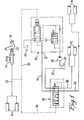
- Figures 1 and 2 illustrate a preferred embodiment wherein this invention is applied to a towing vehicle provided with a pair of front brakes 10 and a pair of rear brakes 12 and a trailer having brakes 14.
- the towing vehicle is provided with a brake master cylinder 16 oper- atable by a vehicle operator through a foot brake pedal 18 interconnected with the plunger 20 of the brake master cylinder.
- the brake master cylinder is capable of delivering pressurized fluid within a first pressure range, this fluid being delivered in the system illustrated through a first fluid line 22 which extends between the brake master cylinder and the front vehicle brakes.
- the towing vehicle is also provided with a trailer brake valve indicated generally at 24.
- This trailer brake valve is of the type illustrated in Figure 3 of U.S. Patent 3718373, it will not be described in detail.
- the towing vehicle is additionally provided with a fluid reservoir 26 and a pump 28 which acts as a source of fluid under pressure for the trailer brake valve 24 via an inlet port 25.
- a pilot line 30 extends between the first fluid line 22 and a trailer brake valve pilot port 27.
- the trailer brake valve will deliver fluid under presure to an outlet port 32 at a pressure range greater than the pressure range exerted by the brake master cylinder.
- the output pressure range of the trailer brake valve is seven times greater than the output pressure range of the brake master cylinder.
- the output pressure range of the trailer brake valve is so selected that it will properly operate the trailer brakes.
- a hydraulic line in the prior art would normally extend from the output port 32 to the trailer brakes.
- the control means includes a pilot operated control valve indicated generally at 34.
- the valve 34 includes a valve body 36 ( Figure 2) provided with an inlet port 38 and first, second and third outlet ports 30, 41, and 42.
- a second fluid line interconnects the inlet port 38 with the outlet port 32 of the trailer brake valve 24.
- a third line or trailer brake line 46 extends from the first outlet port 40 of the control valve 34 to the trailer brakes 14.
- a fourth or vehicle brake line 48 extends from the second outlet port 41 of the control valve 34 to the rear vehicle brakes 12.
- Another line 50 extends between the third outlet port 42 and the reservoir 26.
- the valve body 36 is provided with a cylindrical bore 52, the bore being provided with four axially spaced apart recesses 54, 56, 58, 60 which are associated with the first outlet port 40, the inlet port 38, and the second and third outlet ports 41, 42, respectively.
- the inlet recess 56 is disposed between the first and second outlet recesses 54, 58
- the second outlet recess 58 is disposed between the inlet recess 56 and the third outlet recess 60.
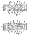
- a valve member in the form of a spool 62 is disposed within the cylindrical bore, the spool being provided with three axially spaced apart lands 64, 66 and 68. Reliefs 70 and 72 are located between adjacent lands.
- a second pilot line 74 which is connected at one end to the output of the master cylinder, extends to a pilot port 100 provided at one end of the cylindrical bore 52.
- the other end of the cylindrical bore is closed to form a chamber within which a spring 76 is disposed, the spring normally biasing the spool to a normal operating position illustrated in Figure 2.
- the spool is further provided with a passageway 78 which extends between the relief 72 which is associated with the outlet port 41 and the closed end of bore 52 which houses the spring 76.
- pilot line pressure in line 30 will in turn cause a portion of the output of pump 28 to be diverted by the trailer brake valve to the outlet port 32 in the pre-selected pressure range.
- Pilot line pressure in pilot line 74 will also cause the valve spool 62 to shift from the position illustrated in Figure 2 to the position illusstrated in Figure 3. This is a balanced spool position. When the spool 62 is in this position there will be an unrestricted passageway between the inlet port 38 and the outlet port 40. This causes the pressure in the trailer brake line 46 to be substantially the same as in the inlet line 44.
- valve spool In the event that the trailer line 46 should break during braking operation (when the outlet port 40 would become open to atmosphere), the valve spool will be shifted to a third position illustrated in Figure 4. In this position the land 66 cooperating with the recess 56 will restrict the flow of fluid from line 44 to the broken trailer brake line 46 whilst still allowing the flow of fluid from the line 44 to the tractor rear brake line 48 thus maintaining a tractor rear brake function. It will be noted that the fluid pressure within the recess 58 will be maintained equal to the pilot line pressure as the spool will be maintained in a balanced position due to passageway 78.
- the present invention has been described in connection with a preferred embodiment in which a master cylinder is utilized to apply the tractor front brakes and the pilot operated control valve is utilized to direct fluid from a trailer brake valve to both trailer brakes and the rear brakes, this invention can be utilized in other applications.
- the pilot operated control valve can be utilized to direct fluid not only to the trailer brakes, but to all of the brakes of the vehicle.
Landscapes
- Engineering & Computer Science (AREA)
- Transportation (AREA)
- Mechanical Engineering (AREA)
- Regulating Braking Force (AREA)
- Braking Systems And Boosters (AREA)
Claims (9)
ledit système étant caractérisé par la présence d'un moyen de commande (34) actionné par une pression pilote comprenant un orifice de pression pilote (100) relié au maître- cylindre (16), un orifice d'entrée (38) relié à l'orifice de sortie (32) de la valve de freinage de la remorque et un premier (40) et un deuxième (41) orifice de sortie, reliés respectivement aux freins de la remorque (14) et du véhicule (12), ledit moyen de commande étant capable, lorsqu'il est actionné, de provoquer l'actionnement hydraulique des freins du véhicule dans ladite première gamme de pression et l'actionnement hydraulique des freins de la remorque dans ladite deuxième gamme de pression.
Applications Claiming Priority (2)
| Application Number | Priority Date | Filing Date | Title |
|---|---|---|---|
| US44785 | 1979-05-31 | ||
| US06/044,785 US4243271A (en) | 1979-05-31 | 1979-05-31 | Hydraulic braking system |
Publications (2)
| Publication Number | Publication Date |
|---|---|
| EP0020105A1 EP0020105A1 (fr) | 1980-12-10 |
| EP0020105B1 true EP0020105B1 (fr) | 1983-12-28 |
Family
ID=21934326
Family Applications (1)
| Application Number | Title | Priority Date | Filing Date |
|---|---|---|---|
| EP80301714A Expired EP0020105B1 (fr) | 1979-05-31 | 1980-05-23 | Système de freinage hydraulique |
Country Status (4)
| Country | Link |
|---|---|
| US (1) | US4243271A (fr) |
| EP (1) | EP0020105B1 (fr) |
| DE (1) | DE3065985D1 (fr) |
| ES (1) | ES491889A0 (fr) |
Families Citing this family (8)
| Publication number | Priority date | Publication date | Assignee | Title |
|---|---|---|---|---|
| EP0114502B1 (fr) * | 1982-12-21 | 1987-09-16 | Wabco Automotive U.K. Limited | Systèmes hydrauliques de freinage |
| FR2563485B1 (fr) * | 1984-04-27 | 1991-05-24 | Bosch Gmbh Robert | Dispositif hydraulique de commande pour dispositif de freinage |
| DE3506137C2 (de) * | 1985-02-22 | 1994-01-13 | Bosch Gmbh Robert | Hydraulische Steuereinrichtung |
| US5368372A (en) * | 1992-10-30 | 1994-11-29 | Total Quality Enterprises, Inc. | Hydraulic brake system for an off-road vehicle |
| US5346289A (en) * | 1992-10-30 | 1994-09-13 | Total Quality Enterprises, Inc. | Control valve for hydraulic braking system |
| US5505528A (en) * | 1993-01-13 | 1996-04-09 | Mico, Inc. | Electric motorized brake-lock system |
| DE102006007575A1 (de) * | 2006-02-18 | 2007-08-23 | Deere & Company, Moline | Hydraulische Anordnung |
| WO2019215298A1 (fr) * | 2018-05-10 | 2019-11-14 | Cnh Industrial Italia S.P.A. | Agencement hydraulique pour circuits hydrauliques de frein de tracteur-remorque |
Family Cites Families (4)
| Publication number | Priority date | Publication date | Assignee | Title |
|---|---|---|---|---|
| DK139665A (fr) * | 1970-11-13 | |||
| US4017125A (en) * | 1975-09-09 | 1977-04-12 | Midland-Ross Corporation | Inversion brake valve and system therefor |
| US4030757A (en) * | 1976-02-17 | 1977-06-21 | Midland-Ross Corporation | Tractor-mounted cargo-trailer brake control system |
| US4076323A (en) * | 1977-05-09 | 1978-02-28 | Caterpillar Tractor Co. | Fluid brake system for a vehicle |
-
1979
- 1979-05-31 US US06/044,785 patent/US4243271A/en not_active Expired - Lifetime
-
1980
- 1980-05-23 EP EP80301714A patent/EP0020105B1/fr not_active Expired
- 1980-05-23 DE DE8080301714T patent/DE3065985D1/de not_active Expired
- 1980-05-27 ES ES491889A patent/ES491889A0/es active Granted
Also Published As
| Publication number | Publication date |
|---|---|
| US4243271A (en) | 1981-01-06 |
| ES8105647A1 (es) | 1981-06-16 |
| ES491889A0 (es) | 1981-06-16 |
| DE3065985D1 (en) | 1984-02-02 |
| EP0020105A1 (fr) | 1980-12-10 |
Similar Documents
| Publication | Publication Date | Title |
|---|---|---|
| US4941712A (en) | Brake fluid pressure control apparatus in an anti-lock control system | |
| US3863991A (en) | Vehicle brake system | |
| US4074528A (en) | Hydraulic control system with priority flow control | |
| EP0026972B1 (fr) | Valve de commande, en particulier pour un système hydraulique d'un véhicule | |
| US3978946A (en) | Parking brake system with transmission interlock | |
| EP0020105B1 (fr) | Système de freinage hydraulique | |
| US4161867A (en) | Hydraulic brake booster | |
| US4000751A (en) | Hydraulic power system with automatic priority-demand flow control means | |
| US3771424A (en) | Hydraulic flow amplifier valve | |
| US4027924A (en) | Anti-skid brake control device for vehicles | |
| US20100187900A1 (en) | Hydraulic power brake system | |
| US5179835A (en) | Brake valve for use in load sensing hydraulic system | |
| US4842340A (en) | Brake for a vehicle trailer | |
| KR920010118B1 (ko) | 차량용 적응 제동 시스템 | |
| US5226701A (en) | Automatic braking device for a vehicle | |
| US4869561A (en) | Three-channel adaptive braking system | |
| US4214446A (en) | Pressure-flow compensated hydraulic priority system providing signals controlling priority valve | |
| US3360303A (en) | System for controlling the braking of a vehicle trailer by a fluid circuit which is independent of the towing vehicle brake circuit and utilized for at least one other function in addition | |
| US4693273A (en) | Control valve | |
| US10315635B2 (en) | Power steering braking valve | |
| GB1564436A (en) | Vihicle steering and brake control | |
| US4583788A (en) | Tractor-trailer brake system | |
| US4095848A (en) | Anti-skid brake control system having a hydraulic brake booster | |
| US4559780A (en) | Power valve for a vehicle braking system | |
| US4106818A (en) | Braking system for vehicle |
Legal Events
| Date | Code | Title | Description |
|---|---|---|---|
| PUAI | Public reference made under article 153(3) epc to a published international application that has entered the european phase |
Free format text: ORIGINAL CODE: 0009012 |
|
| AK | Designated contracting states |
Designated state(s): DE FR GB IT |
|
| 17P | Request for examination filed |
Effective date: 19810605 |
|
| ITF | It: translation for a ep patent filed | ||
| GRAA | (expected) grant |
Free format text: ORIGINAL CODE: 0009210 |
|
| AK | Designated contracting states |
Designated state(s): DE FR GB IT |
|
| REF | Corresponds to: |
Ref document number: 3065985 Country of ref document: DE Date of ref document: 19840202 |
|
| ET | Fr: translation filed | ||
| PGFP | Annual fee paid to national office [announced via postgrant information from national office to epo] |
Ref country code: FR Payment date: 19840613 Year of fee payment: 5 |
|
| PGFP | Annual fee paid to national office [announced via postgrant information from national office to epo] |
Ref country code: DE Payment date: 19840628 Year of fee payment: 5 |
|
| PLBE | No opposition filed within time limit |
Free format text: ORIGINAL CODE: 0009261 |
|
| STAA | Information on the status of an ep patent application or granted ep patent |
Free format text: STATUS: NO OPPOSITION FILED WITHIN TIME LIMIT |
|
| 26N | No opposition filed | ||
| PG25 | Lapsed in a contracting state [announced via postgrant information from national office to epo] |
Ref country code: GB Effective date: 19880523 |
|
| PG25 | Lapsed in a contracting state [announced via postgrant information from national office to epo] |
Ref country code: FR Free format text: LAPSE BECAUSE OF NON-PAYMENT OF DUE FEES Effective date: 19890131 |
|
| GBPC | Gb: european patent ceased through non-payment of renewal fee | ||
| PG25 | Lapsed in a contracting state [announced via postgrant information from national office to epo] |
Ref country code: DE Effective date: 19890201 |
|
| REG | Reference to a national code |
Ref country code: FR Ref legal event code: ST |