EP0020032B1 - Hydraulic power assisted steering system - Google Patents
Hydraulic power assisted steering system Download PDFInfo
- Publication number
- EP0020032B1 EP0020032B1 EP19800301453 EP80301453A EP0020032B1 EP 0020032 B1 EP0020032 B1 EP 0020032B1 EP 19800301453 EP19800301453 EP 19800301453 EP 80301453 A EP80301453 A EP 80301453A EP 0020032 B1 EP0020032 B1 EP 0020032B1
- Authority
- EP
- European Patent Office
- Prior art keywords
- fluid pressure
- source
- valve
- clutch means
- pressure
- Prior art date
- Legal status (The legal status is an assumption and is not a legal conclusion. Google has not performed a legal analysis and makes no representation as to the accuracy of the status listed.)
- Expired
Links
- 239000012530 fluid Substances 0.000 claims description 54
- 238000006073 displacement reaction Methods 0.000 claims description 9
- 238000011144 upstream manufacturing Methods 0.000 claims description 4
- 238000006243 chemical reaction Methods 0.000 claims description 2
- 230000000694 effects Effects 0.000 description 6
- 229910000831 Steel Inorganic materials 0.000 description 2
- 238000012986 modification Methods 0.000 description 2
- 230000004048 modification Effects 0.000 description 2
- 239000010959 steel Substances 0.000 description 2
- 238000010276 construction Methods 0.000 description 1
- 230000003292 diminished effect Effects 0.000 description 1
Images

Classifications
-
- B—PERFORMING OPERATIONS; TRANSPORTING
- B62—LAND VEHICLES FOR TRAVELLING OTHERWISE THAN ON RAILS
- B62D—MOTOR VEHICLES; TRAILERS
- B62D6/00—Arrangements for automatically controlling steering depending on driving conditions sensed and responded to, e.g. control circuits
Definitions
- This invention relates to an hydraulic power assisted steering system. More particularly, the invention concerns such a system in which the assistance pressure is controlled by a servo control valve comprising two valve elements which are displaceable relative to each other and are subject to restraint by elastic torque means, usually in the form of a torque rod, and in which fluid pressure from an appropriate source reacts on clutch means which is operative between the two valve elements and serves to resist relative displacement of those two elements - the resistance which is effected by the clutch means being a function of the fluid pressure which is applied to the clutch means from the fluid pressure source.
- a servo control valve comprising two valve elements which are displaceable relative to each other and are subject to restraint by elastic torque means, usually in the form of a torque rod, and in which fluid pressure from an appropriate source reacts on clutch means which is operative between the two valve elements and serves to resist relative displacement of those two elements - the resistance which is effected by the clutch means being a function of the fluid pressure which is applied to the clutch means from the fluid pressure source.
- valve elements are in the form of two relatively rotatable valve components which are subject to restraint by an elastic torque rod and relative rotation between which determines the flow of fluid under pressure from the pressure source to power assistance means (usually a double acting piston and cylinder device) of the steering system while the pressure source additionally communicates with the clutch means which is operative between the two relatively rotatable valve components.
- power assistance means usually a double acting piston and cylinder device
- the clutch means in the prior proposals is in the form of detent means which is responsive to the fluid pressure which is applied thereto and acts to resist the relative rotation of the two valve components by reason of inter-acting surfaces of the detent means being urged (by the source pressure) into engagement so that the resistance is a function of the source pressure and of the profiles of the inter-acting surfaces of the detent means.
- U.K. Patent No. 1,432,555 there is disclosed the possibility of providing a valve between the clutch means and the fluid pressure source for controlling fluid pressure available from the source to the clutch means.
- the source pressure may be derived from an engine driven pump whereby the output from the pump is proportional to engine speed so that, as discussed in our U.K. Patent Specification No. 1,470,975, when the engine is idling or at relatively low speed the clutch means may be disengaged and relative rotation between the valve components is resisted solely by the elastic torque means whereas when the engine is running at high speed the clutch means may be subjected to considerable fluid pressure and increasingly resist relative rotation between the valve components to an extent whereby those components may effectively become locked together (the steering system then being responsive wholly to a manual input and no power assistance is provided).
- the source pressure may be derived from a pump the output of which is proportional to vehicle speed whereby at low vehicle speed (or when the vehicle is stationary) the clutch means is subjected to low fluid pressure so that power assistance is readily available by relative rotation between the valve components while at higher vehicle speeds the clutch means can be subjected to considerable fluid pressure so that the valve components are increasingly restrained from relative rotation (and may effectively become locked together as mentioned above so that no power assistance is available).
- the possibility of a complete loss of power assistance when the vehicle is at high speed may be undesirable.
- an hydraulic power assisted steering system in which the assistance pressure is controlled by a servo control valve comprising two valve elements which are displaceable relative to each other and are subject to restraint by elastic torque means; a source of fluid under pressure, fluid pressure from which reacts on clutch means operative between the two valve elements, said clutch means resisting relative displacement of the two elements and the resistance effected thereby being a function of the fluid pressure which is applied thereto from the source; auxiliary valve means interposed in the system between the source and the clutch means and controlling fluid pressure available from the source to the clutch means characterised in that the auxiliary valve means is responsive to fluid pressure applied thereto from the source and reacts in response to variations in that fluid pressure to close fluid pressure communication between the source and the clutch means when the source pressure attains a predetermined value so that the clutch means provides a maximum resistance to relative displacement of the two elements which is less than that consistent with the two elements being substantially locked together.
- the auxiliary valve means comprises a displaceable component which is biased to a condition in which maximum communication is available for fluid pressure between the source and the clutch means and which component is displaceable against its biasing to decrease the fluid pressure available to the clutch means by the reaction on the component of fluid pressure from the source when that fluid pressure attains a predetermined value.
- the assistance/servo motor (usually in the form of a double acting piston and cylinder device as aforementioned) of the steering system is supplied by the fluid pressure source, such supply being branched from the supply to the clutch means (at a position upstream of the auxiliary valve means) and being subject to the control of the servo control valve.
- the source of fluid under pressure will usually be derived from an engine driven pump as aforementioned and since the auxiliary valve means is pressure sensitive it will be apparent that the system of the invention is particularly, but not essentially, suitable for use with a constant volume (variable pressure) output pump.
- the system shown in Figure 1 has a stationary valve housing 1 in which is a rotatable outer valve element 2 within which, and extending from the bore of the housing 1, is rotatably mounted an inner valve element 3.
- the valve element 3 includes an input shaft 4 which is to be rotated by the steering column of a vehicle in which the system is fitted.
- a pinion 5 Connected for positive rotation with the valve element 2 is a pinion 5 which engages with the rack of a rack bar (not shown) displacement of which in response to rotation of the pinion 5 effects a steering manoeuvre in conventional manner.
- a power assistance/servo motor such as a double acting piston and cylinder device the admission and exhausting of fluid pressure to and from which provides power assistance in conventional manner.
- an elastic torque rod 6 Located within and extending axially through a bore in the valve element 3 is an elastic torque rod 6 which is connected at one end to the valve element 3 and at its other end to the pinion 5 (and thereby to the valve element 2) in conventional manner.
- valve elements 2 and 3 form a servo controlled valve having conventional pressure chamber and passages (indicated at 7) generally provided for such valves and usually in the form of circumferential or axially co-operating grooves and slits to connect the power assistance/servo motor by way of outlet ports 8 and 9 alternatively to fluid pressure at an input port 10 or an exhaust port 11 (communicating by way of a return line to a fluid reservoir 12).
- Fluid pressure to the port 10 is derived from a pump 13 driven by the engine of a vehicle to which the steering system is fitted, such a pump drawing hydraulic fluid from the reservoir 12.
- the output from pump 13 is branched through lines 14 and 15, line 14 communicating with the inlet port 10 and thereby serving to actuate the power assistance/servo motor under control of the valve 7.
- the line 15 communicates by way of an auxiliary valve 16 and a port 17 with an annular pressure chamber 18 formed between the outer valve element 2 and the housing 1.
- Located within the chamber 18 is a fluid pressure responsive clutch device 19 which is engageable between the inner and outer valve elements 2 and 3.
- the clutch device 19 is similar in construction and general operation to that disclosed in our U.K. Patent Specification No.
- 1,470,975 and comprises radial bores 20 in the element 3 which communicate with the chamber 18 and in which are slidable steel balls 21.
- two diametrically opposed steel balls 21 are provided which are displaceable in their respective bores 20 to be engaged with generally V-sectioned recesses 22 in the valve element 3.
- the balls 21 are urged radially inwardly in response to an increase in fluid pressure in the chamber 18 to engage the grooves 22 and thereby resist relative rotation between the valve elements 2 and 3 between which the balls 21 co-operate.
- the valve elements 2 and 3 will thereby become increasingly locked together as fluid pressure increases in the chamber 18.
- the pump 13 is driven by the vehicle engine and provides a substantially constant volume output so that the fluid pressure in lines 14 and 15 varies in accordance with the demand on the pump.
- the port 17 which feeds the clutch device 19 would communicate directly with the output from the pump 13 and consequently the hydraulic pressure in chamber 18 would always be directly proportional to the demand on the pump 13.
- the effect of this latter arrangement may be that when the demand on the pump is sufficiently high (for example during actuation of the assistance/servo motor) the fluid pressure acting on the balls 21 in the clutch device may be sufficient to positively interlock the elements 2 and 3 so that they rotate in unison in response to a steering manoeuvre and thus the valve 7 becomes inoperative and the steering system is wholly manual.
- auxiliary valve 16 as shown in Figure 3 which primarily serves to determine the maximum hydraulic pressure to which the clutch device 19 is subjected in the chamber 1 8, so that such pressure is less than that which is required for the clutch device effectively to lock the valve elements 2 and 3 together.
- the valve 16 comprises a spool 23 axially slidable in a spool cylinder 24 formed by a spool housing 25 which can conveniently be carried by or integral with the valve housing 1 or a housing of the pump 13.
- the spool 23 has an annular recess 26 and is biased by a spring 27 so that the line 15 communicates through the recess 26 to direct fluid pressure from the pump to the port 17.
- the spool 23 is biased by spring 27 so that the chamber 28 is normally in a contracted condition.
- the spool 23 is subjected to a fluid force differential for which purpose the spool has a spool rod 23a slidable in a reduced diameter spool cylinder part 24a.
- a second spool chamber 28a which is in constant communication by way of line 15b with the line 15 at a position upstream of the spool cylinder 24 and downstream of the pump 13.
- the pressurised area of the end face of the spool rod 23a in the chamber 28a is less than the pressurised area of the end face of the spool in the chamber 28 and since both chambers 28 and 28a are subjected to the same fluid pressure from pump 13 the spool will be subjected to a fluid force differential which, when sufficient, will cause displacement of the spool leftwardly in Figure 4 against the biasing spring 27 with similar effect on the system as that previously described for the valve in Figure 3.
Landscapes
- Engineering & Computer Science (AREA)
- Chemical & Material Sciences (AREA)
- Combustion & Propulsion (AREA)
- Transportation (AREA)
- Mechanical Engineering (AREA)
- Power Steering Mechanism (AREA)
Description
- This invention relates to an hydraulic power assisted steering system. More particularly, the invention concerns such a system in which the assistance pressure is controlled by a servo control valve comprising two valve elements which are displaceable relative to each other and are subject to restraint by elastic torque means, usually in the form of a torque rod, and in which fluid pressure from an appropriate source reacts on clutch means which is operative between the two valve elements and serves to resist relative displacement of those two elements - the resistance which is effected by the clutch means being a function of the fluid pressure which is applied to the clutch means from the fluid pressure source. Examples of power assisted steering systems as above described are disclosed in U.K. Patent Specification No. 1,432,555 and in our U.K. Patent Specifications Nos. 1,470,975 and 1,465,901 in which the valve elements are in the form of two relatively rotatable valve components which are subject to restraint by an elastic torque rod and relative rotation between which determines the flow of fluid under pressure from the pressure source to power assistance means (usually a double acting piston and cylinder device) of the steering system while the pressure source additionally communicates with the clutch means which is operative between the two relatively rotatable valve components. The clutch means in the prior proposals is in the form of detent means which is responsive to the fluid pressure which is applied thereto and acts to resist the relative rotation of the two valve components by reason of inter-acting surfaces of the detent means being urged (by the source pressure) into engagement so that the resistance is a function of the source pressure and of the profiles of the inter-acting surfaces of the detent means. In U.K. Patent No. 1,432,555 there is disclosed the possibility of providing a valve between the clutch means and the fluid pressure source for controlling fluid pressure available from the source to the clutch means.
- In known systems as above described the source pressure may be derived from an engine driven pump whereby the output from the pump is proportional to engine speed so that, as discussed in our U.K. Patent Specification No. 1,470,975, when the engine is idling or at relatively low speed the clutch means may be disengaged and relative rotation between the valve components is resisted solely by the elastic torque means whereas when the engine is running at high speed the clutch means may be subjected to considerable fluid pressure and increasingly resist relative rotation between the valve components to an extent whereby those components may effectively become locked together (the steering system then being responsive wholly to a manual input and no power assistance is provided). The aforementioned conditions whereby the clutch means is disengaged when the vehicle engine is running at low speed or idling and progressively engages as the engine speed increases are desirable provided that such variations in engine speed are related to corresponding variations in vehicle speed (since it is accepted that maximum power assistance is desirable when the vehicle is at low speed, for example during parking manoeuvres, whereas minimum power assistance is required when the vehicle is running at high speed). However it is found that occasionally the vehicle engine is running at high speed while the vehicle is at low speed (such as during a parking manoeuvre with a high revving engine) and in the prior proposals this could correspond with the undesirable effect that the power assistance available is diminished even though the vehicle is slow moving in a parking manoeuvre. In a further known system, such as is disclosed in our U.K. Patent Specification No. 1,465,901, the source pressure may be derived from a pump the output of which is proportional to vehicle speed whereby at low vehicle speed (or when the vehicle is stationary) the clutch means is subjected to low fluid pressure so that power assistance is readily available by relative rotation between the valve components while at higher vehicle speeds the clutch means can be subjected to considerable fluid pressure so that the valve components are increasingly restrained from relative rotation (and may effectively become locked together as mentioned above so that no power assistance is available). For some steering gear designs the possibility of a complete loss of power assistance when the vehicle is at high speed may be undesirable.
- It is an object of the present invention to provide a relatively simple and inexpensive modification to steering systems similar to that disclosed in U.K. Patent Specification No. 1432555 and in our U.K. Specifications Nos. 1,470,975 and 1,465,901, whereby a predetermined proportion of power assistance for a steering manoeuvre is available irrespective of the maximum pressure provided by the fluid pressure source.
- According to the present invention there is provided an hydraulic power assisted steering system in which the assistance pressure is controlled by a servo control valve comprising two valve elements which are displaceable relative to each other and are subject to restraint by elastic torque means; a source of fluid under pressure, fluid pressure from which reacts on clutch means operative between the two valve elements, said clutch means resisting relative displacement of the two elements and the resistance effected thereby being a function of the fluid pressure which is applied thereto from the source; auxiliary valve means interposed in the system between the source and the clutch means and controlling fluid pressure available from the source to the clutch means characterised in that the auxiliary valve means is responsive to fluid pressure applied thereto from the source and reacts in response to variations in that fluid pressure to close fluid pressure communication between the source and the clutch means when the source pressure attains a predetermined value so that the clutch means provides a maximum resistance to relative displacement of the two elements which is less than that consistent with the two elements being substantially locked together.
- Desirably the auxiliary valve means comprises a displaceable component which is biased to a condition in which maximum communication is available for fluid pressure between the source and the clutch means and which component is displaceable against its biasing to decrease the fluid pressure available to the clutch means by the reaction on the component of fluid pressure from the source when that fluid pressure attains a predetermined value.
- Similar to the arrangement disclosed in our U.K. Patent Specification No. 1,470,975, it is preferred, that the assistance/servo motor (usually in the form of a double acting piston and cylinder device as aforementioned) of the steering system is supplied by the fluid pressure source, such supply being branched from the supply to the clutch means (at a position upstream of the auxiliary valve means) and being subject to the control of the servo control valve. The source of fluid under pressure will usually be derived from an engine driven pump as aforementioned and since the auxiliary valve means is pressure sensitive it will be apparent that the system of the invention is particularly, but not essentially, suitable for use with a constant volume (variable pressure) output pump.
- One embodiment of an hydraulic power assisted steering system constructed in accordance with the present invention will now be described, by way of example only, with reference to the accompanying illustrative drawings in which:-
- Figure 1 schematically illustrates the system in which the servo control and clutch means have been shown in part section and in which, for convenience, the assistance/servo motor (such as a conventional double acting piston and cylinder device) has been omitted;
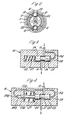
- Figure 2 is a section through the servo control valve taken on the line A-A in Figure 1 to illustrate the clutch means;
- Figure 3 is a sectional view of an auxiliary valve means which is incorporated in the system of Figure 1, and
- Figure 4 shows an alternative and modified form of auxiliary valve means which can be substituted for the valve means shown in Figure 3.
- The system shown in Figure 1 has a stationary valve housing 1 in which is a rotatable
outer valve element 2 within which, and extending from the bore of the housing 1, is rotatably mounted aninner valve element 3. Thevalve element 3 includes an input shaft 4 which is to be rotated by the steering column of a vehicle in which the system is fitted. Connected for positive rotation with thevalve element 2 is apinion 5 which engages with the rack of a rack bar (not shown) displacement of which in response to rotation of thepinion 5 effects a steering manoeuvre in conventional manner. Associated with the rack bar is a power assistance/servo motor such as a double acting piston and cylinder device the admission and exhausting of fluid pressure to and from which provides power assistance in conventional manner. Located within and extending axially through a bore in thevalve element 3 is anelastic torque rod 6 which is connected at one end to thevalve element 3 and at its other end to the pinion 5 (and thereby to the valve element 2) in conventional manner. - The
valve elements outlet ports 8 and 9 alternatively to fluid pressure at aninput port 10 or an exhaust port 11 (communicating by way of a return line to a fluid reservoir 12). - Fluid pressure to the
port 10 is derived from apump 13 driven by the engine of a vehicle to which the steering system is fitted, such a pump drawing hydraulic fluid from thereservoir 12. The output frompump 13 is branched throughlines line 14 communicating with theinlet port 10 and thereby serving to actuate the power assistance/servo motor under control of the valve 7. Theline 15 communicates by way of anauxiliary valve 16 and aport 17 with anannular pressure chamber 18 formed between theouter valve element 2 and the housing 1. Located within thechamber 18 is a fluid pressureresponsive clutch device 19 which is engageable between the inner andouter valve elements clutch device 19 is similar in construction and general operation to that disclosed in our U.K. Patent Specification No. 1,470,975 and comprisesradial bores 20 in theelement 3 which communicate with thechamber 18 and in which areslidable steel balls 21. As shown in Figure 2 two diametrically opposedsteel balls 21 are provided which are displaceable in theirrespective bores 20 to be engaged with generally V-sectionedrecesses 22 in thevalve element 3. As is known from the discussion in our U.K. Patent Specification No. 1,470,975 theballs 21 are urged radially inwardly in response to an increase in fluid pressure in thechamber 18 to engage thegrooves 22 and thereby resist relative rotation between thevalve elements balls 21 co-operate. Thevalve elements chamber 18. During such restraint to relative rotation between theelements torque rod 6 is increasingly shunted out and thereby the operation of the control valve 7 becomes increasingly less torque sensitive to cause less power assistance to be available (and thereby greater manual effort being required) to effect a steering manoeuvre. - The
pump 13 is driven by the vehicle engine and provides a substantially constant volume output so that the fluid pressure inlines - Following from the teaching in our U.K. Patent Specification No. 1,470,975, the
port 17 which feeds theclutch device 19 would communicate directly with the output from thepump 13 and consequently the hydraulic pressure inchamber 18 would always be directly proportional to the demand on thepump 13. The effect of this latter arrangement may be that when the demand on the pump is sufficiently high (for example during actuation of the assistance/servo motor) the fluid pressure acting on theballs 21 in the clutch device may be sufficient to positively interlock theelements line 15 theauxiliary valve 16 as shown in Figure 3 which primarily serves to determine the maximum hydraulic pressure to which theclutch device 19 is subjected in the chamber 1 8, so that such pressure is less than that which is required for the clutch device effectively to lock thevalve elements - The
valve 16 comprises aspool 23 axially slidable in aspool cylinder 24 formed by aspool housing 25 which can conveniently be carried by or integral with the valve housing 1 or a housing of thepump 13. Thespool 23 has anannular recess 26 and is biased by aspring 27 so that theline 15 communicates through therecess 26 to direct fluid pressure from the pump to theport 17. Formed between an end face of thespool 23 and an end of thespool cylinder 24 is aspool chamber 28 which is in constant communication by way of line 1 5a with theline 15 at a position upstream of thespool 23 and downstream of thepump 13. Thespool 23 is biased byspring 27 so that thechamber 28 is normally in a contracted condition. As the fluid pressure output frompump 13 increases it will be apparent from Figure 3 that fluid pressure increases in theline 15 and thereby in thechamber 28 to urge thespool 23 in a sense which displaces it leftwardly in Figure 3 against its spring biasing. During such displacement of thespool 23 theline 15 is progressively closed by the full diameter of the spool to communication with therecess 26; consequently the fluid pressure supplied to theclutch device 19 will progressively decrease as fluid pressure increases in thechamber 28 until, at a predetermined pressure, thespool 23 is sufficiently displaced to closeline 15 and thereby determine the maximum pressure to which theballs 21 are subjected (and thereby the maximum interlocking effect which the balls have between thevalve elements 2 and 3). Desirably thevalve 16 is arranged so that theline 15 closes when relative rotational displacement is permissible between thevalve elements - In the modification of the
auxiliary valve 16 as shown in Figure 4 thespool 23 is subjected to a fluid force differential for which purpose the spool has a spool rod 23a slidable in a reduced diameter spool cylinder part 24a. Formed between the end face of the spool rod 23a and the end of the spool cylinder part 24a is a second spool chamber 28a which is in constant communication by way of line 15b with theline 15 at a position upstream of thespool cylinder 24 and downstream of thepump 13. The pressurised area of the end face of the spool rod 23a in the chamber 28a is less than the pressurised area of the end face of the spool in thechamber 28 and since bothchambers 28 and 28a are subjected to the same fluid pressure frompump 13 the spool will be subjected to a fluid force differential which, when sufficient, will cause displacement of the spool leftwardly in Figure 4 against the biasingspring 27 with similar effect on the system as that previously described for the valve in Figure 3.
Claims (5)
Applications Claiming Priority (2)
| Application Number | Priority Date | Filing Date | Title |
|---|---|---|---|
| GB7918438A GB2088795B (en) | 1980-10-31 | 1979-05-25 | Hydraulic power assisted steering system |
| GB7918438 | 1979-05-25 |
Publications (2)
| Publication Number | Publication Date |
|---|---|
| EP0020032A1 EP0020032A1 (en) | 1980-12-10 |
| EP0020032B1 true EP0020032B1 (en) | 1984-03-21 |
Family
ID=10505478
Family Applications (1)
| Application Number | Title | Priority Date | Filing Date |
|---|---|---|---|
| EP19800301453 Expired EP0020032B1 (en) | 1979-05-25 | 1980-05-02 | Hydraulic power assisted steering system |
Country Status (2)
| Country | Link |
|---|---|
| EP (1) | EP0020032B1 (en) |
| DE (1) | DE3067098D1 (en) |
Families Citing this family (1)
| Publication number | Priority date | Publication date | Assignee | Title |
|---|---|---|---|---|
| AU568946B2 (en) * | 1984-08-08 | 1988-01-14 | Bishop Steering Technology Limited | Power steering control valve |
Family Cites Families (3)
| Publication number | Priority date | Publication date | Assignee | Title |
|---|---|---|---|---|
| GB1432555A (en) * | 1972-09-08 | 1976-04-22 | Burman & Sons Ltd | Power-assisted steering gear |
| GB1465901A (en) * | 1973-02-01 | 1977-03-02 | Cam Gears Ltd | Power assisted vehicle steering |
| GB1470975A (en) * | 1973-07-18 | 1977-04-21 | Cam Gears Ltd | Power assisted steering system |
-
1980
- 1980-05-02 EP EP19800301453 patent/EP0020032B1/en not_active Expired
- 1980-05-02 DE DE8080301453T patent/DE3067098D1/en not_active Expired
Also Published As
| Publication number | Publication date |
|---|---|
| DE3067098D1 (en) | 1984-04-26 |
| EP0020032A1 (en) | 1980-12-10 |
Similar Documents
| Publication | Publication Date | Title |
|---|---|---|
| US4034825A (en) | Power assisted vehicle steering | |
| EP0302267B1 (en) | Power steering system | |
| US4620416A (en) | Load sensing system | |
| US4570736A (en) | Dual flow variable assist power steering gear mechanism | |
| US3465842A (en) | Power steering mechanism | |
| US3998131A (en) | Rotary valve for power steering with hydraulic reaction | |
| US4434866A (en) | Speed-sensitive power steering system | |
| EP0502456B1 (en) | Fluid controller with load sensing priority flow control capability | |
| US5620026A (en) | Fluid controller and improved backflow prevention therefor | |
| GB2088795A (en) | Hydraulic power assisted steering system | |
| US4640148A (en) | Steering mechanism of rack-and-pinion type | |
| US5392875A (en) | Hydraulic reaction variable assist power steering system | |
| GB1519062A (en) | Controller assembly for use in a vehicle steering system | |
| US4558720A (en) | Closed-center controller for use with unequal area cylinder | |
| JPH0645343B2 (en) | Steering force control device for power steering device | |
| EP0480431B1 (en) | Controller with reduced travel limit slip | |
| GB2026963A (en) | Power steering apparatus | |
| JPH0544385B2 (en) | ||
| US5593002A (en) | Power steering system equipped with means for varying an assist torque thereof | |
| EP0020032A1 (en) | Hydraulic power assisted steering system | |
| US4365683A (en) | Power assisted vehicle steering system | |
| US5046573A (en) | Automotive power steering system | |
| US3990534A (en) | Power steering system | |
| US5069301A (en) | Vehicle power assisted steering system | |
| US5667034A (en) | Power steering system |
Legal Events
| Date | Code | Title | Description |
|---|---|---|---|
| PUAI | Public reference made under article 153(3) epc to a published international application that has entered the european phase |
Free format text: ORIGINAL CODE: 0009012 |
|
| AK | Designated contracting states |
Designated state(s): DE FR IT NL SE |
|
| 17P | Request for examination filed |
Effective date: 19810604 |
|
| ITF | It: translation for a ep patent filed | ||
| GRAA | (expected) grant |
Free format text: ORIGINAL CODE: 0009210 |
|
| AK | Designated contracting states |
Designated state(s): DE FR IT NL SE |
|
| REF | Corresponds to: |
Ref document number: 3067098 Country of ref document: DE Date of ref document: 19840426 |
|
| ET | Fr: translation filed | ||
| PGFP | Annual fee paid to national office [announced via postgrant information from national office to epo] |
Ref country code: FR Payment date: 19840517 Year of fee payment: 5 |
|
| PGFP | Annual fee paid to national office [announced via postgrant information from national office to epo] |
Ref country code: DE Payment date: 19840526 Year of fee payment: 5 |
|
| PGFP | Annual fee paid to national office [announced via postgrant information from national office to epo] |
Ref country code: SE Payment date: 19840630 Year of fee payment: 5 |
|
| PLBE | No opposition filed within time limit |
Free format text: ORIGINAL CODE: 0009261 |
|
| STAA | Information on the status of an ep patent application or granted ep patent |
Free format text: STATUS: NO OPPOSITION FILED WITHIN TIME LIMIT |
|
| 26N | No opposition filed | ||
| PGFP | Annual fee paid to national office [announced via postgrant information from national office to epo] |
Ref country code: NL Payment date: 19860531 Year of fee payment: 7 |
|
| PG25 | Lapsed in a contracting state [announced via postgrant information from national office to epo] |
Ref country code: SE Effective date: 19870503 |
|
| PG25 | Lapsed in a contracting state [announced via postgrant information from national office to epo] |
Ref country code: NL Effective date: 19871201 |
|
| NLV4 | Nl: lapsed or anulled due to non-payment of the annual fee | ||
| PG25 | Lapsed in a contracting state [announced via postgrant information from national office to epo] |
Ref country code: FR Free format text: LAPSE BECAUSE OF NON-PAYMENT OF DUE FEES Effective date: 19880129 |
|
| PG25 | Lapsed in a contracting state [announced via postgrant information from national office to epo] |
Ref country code: DE Effective date: 19880202 |
|
| REG | Reference to a national code |
Ref country code: FR Ref legal event code: ST |
|
| EUG | Se: european patent has lapsed |
Ref document number: 80301453.9 Effective date: 19880330 |