EP0020024B1 - Servo control system operable on digital basis - Google Patents
Servo control system operable on digital basis Download PDFInfo
- Publication number
- EP0020024B1 EP0020024B1 EP80301369A EP80301369A EP0020024B1 EP 0020024 B1 EP0020024 B1 EP 0020024B1 EP 80301369 A EP80301369 A EP 80301369A EP 80301369 A EP80301369 A EP 80301369A EP 0020024 B1 EP0020024 B1 EP 0020024B1
- Authority
- EP
- European Patent Office
- Prior art keywords
- signal
- producing
- velocity
- control system
- responsive
- Prior art date
- Legal status (The legal status is an assumption and is not a legal conclusion. Google has not performed a legal analysis and makes no representation as to the accuracy of the status listed.)
- Expired
Links
Images






Classifications
-
- G—PHYSICS
- G05—CONTROLLING; REGULATING
- G05B—CONTROL OR REGULATING SYSTEMS IN GENERAL; FUNCTIONAL ELEMENTS OF SUCH SYSTEMS; MONITORING OR TESTING ARRANGEMENTS FOR SUCH SYSTEMS OR ELEMENTS
- G05B19/00—Program-control systems
- G05B19/02—Program-control systems electric
- G05B19/18—Numerical control [NC], i.e. automatically operating machines, in particular machine tools, e.g. in a manufacturing environment, so as to execute positioning, movement or co-ordinated operations by means of program data in numerical form
- G05B19/19—Numerical control [NC], i.e. automatically operating machines, in particular machine tools, e.g. in a manufacturing environment, so as to execute positioning, movement or co-ordinated operations by means of program data in numerical form characterised by positioning or contouring control systems, e.g. to control position from one programmed point to another or to control movement along a programmed continuous path
- G05B19/33—Numerical control [NC], i.e. automatically operating machines, in particular machine tools, e.g. in a manufacturing environment, so as to execute positioning, movement or co-ordinated operations by means of program data in numerical form characterised by positioning or contouring control systems, e.g. to control position from one programmed point to another or to control movement along a programmed continuous path using an analogue measuring device
- G05B19/35—Numerical control [NC], i.e. automatically operating machines, in particular machine tools, e.g. in a manufacturing environment, so as to execute positioning, movement or co-ordinated operations by means of program data in numerical form characterised by positioning or contouring control systems, e.g. to control position from one programmed point to another or to control movement along a programmed continuous path using an analogue measuring device for point-to-point control
- G05B19/351—Numerical control [NC], i.e. automatically operating machines, in particular machine tools, e.g. in a manufacturing environment, so as to execute positioning, movement or co-ordinated operations by means of program data in numerical form characterised by positioning or contouring control systems, e.g. to control position from one programmed point to another or to control movement along a programmed continuous path using an analogue measuring device for point-to-point control the positional error is used to control continuously the servomotor according to its magnitude
- G05B19/353—Numerical control [NC], i.e. automatically operating machines, in particular machine tools, e.g. in a manufacturing environment, so as to execute positioning, movement or co-ordinated operations by means of program data in numerical form characterised by positioning or contouring control systems, e.g. to control position from one programmed point to another or to control movement along a programmed continuous path using an analogue measuring device for point-to-point control the positional error is used to control continuously the servomotor according to its magnitude with speed feedback only
-
- G—PHYSICS
- G05—CONTROLLING; REGULATING
- G05B—CONTROL OR REGULATING SYSTEMS IN GENERAL; FUNCTIONAL ELEMENTS OF SUCH SYSTEMS; MONITORING OR TESTING ARRANGEMENTS FOR SUCH SYSTEMS OR ELEMENTS
- G05B19/00—Program-control systems
- G05B19/02—Program-control systems electric
- G05B19/18—Numerical control [NC], i.e. automatically operating machines, in particular machine tools, e.g. in a manufacturing environment, so as to execute positioning, movement or co-ordinated operations by means of program data in numerical form
- G05B19/19—Numerical control [NC], i.e. automatically operating machines, in particular machine tools, e.g. in a manufacturing environment, so as to execute positioning, movement or co-ordinated operations by means of program data in numerical form characterised by positioning or contouring control systems, e.g. to control position from one programmed point to another or to control movement along a programmed continuous path
- G05B19/21—Numerical control [NC], i.e. automatically operating machines, in particular machine tools, e.g. in a manufacturing environment, so as to execute positioning, movement or co-ordinated operations by means of program data in numerical form characterised by positioning or contouring control systems, e.g. to control position from one programmed point to another or to control movement along a programmed continuous path using an incremental digital measuring device
- G05B19/23—Numerical control [NC], i.e. automatically operating machines, in particular machine tools, e.g. in a manufacturing environment, so as to execute positioning, movement or co-ordinated operations by means of program data in numerical form characterised by positioning or contouring control systems, e.g. to control position from one programmed point to another or to control movement along a programmed continuous path using an incremental digital measuring device for point-to-point control
- G05B19/231—Numerical control [NC], i.e. automatically operating machines, in particular machine tools, e.g. in a manufacturing environment, so as to execute positioning, movement or co-ordinated operations by means of program data in numerical form characterised by positioning or contouring control systems, e.g. to control position from one programmed point to another or to control movement along a programmed continuous path using an incremental digital measuring device for point-to-point control the positional error is used to control continuously the servomotor according to its magnitude
- G05B19/232—Numerical control [NC], i.e. automatically operating machines, in particular machine tools, e.g. in a manufacturing environment, so as to execute positioning, movement or co-ordinated operations by means of program data in numerical form characterised by positioning or contouring control systems, e.g. to control position from one programmed point to another or to control movement along a programmed continuous path using an incremental digital measuring device for point-to-point control the positional error is used to control continuously the servomotor according to its magnitude with speed feedback only
Definitions
- This invention relates to a servo control system responsive in general to a sequence of position commands supplied from an external source for intermittently and controllably driving a motor, with rotation of the motor fed back, to position a movable element at successively commanded positions substantially at rest. More particularly, this invention relates to a digital servo control system for use in a position control or positioning control system for either a carriage of a serial printer of the type known as an impact type in the art or a type wheel, drum, or cylinder carried by the carriage.
- an impact type serial printer is for use in combination with an electronic digital computer and comprises a carriage, a carriage motor for linearly moving the carriage along a predetermined path in either of two senses along the path, and a position control system for controllably driving the motor so as to successively and intermittently position the carriage at rest at positions commanded by the computer along the path.
- a rotary type wheel carrying a plurality of type elements is mounted on the carriage together with a type wheel motor for rotating the type wheel in either of two senses of rotation.
- a similar position control system controllably drives the wheel motor so as to intermittently position the wheel at rest at desired angular or rotational positions commanded also by the computer. Successively selected type elements are thereby placed at a common printing position predetermined relative to the carriage.
- a position control system for controllably positioning a movable element, such as the carriage or the type wheel mentioned above, to a commanded position comprises an increment encoder or position transducer mechanically or otherwise coupled to a motor for the element. It is already known in the art to make the encoder produce a pair of incremental position signals having polarities that vary with a phase difference therebetween in response to every predetermined incremental angle of rotation of the motor. The successive variations in the polarity therefore correspond to a variation in the present or instantaneous angular position of the motor and hence the present linear or angular position of the movable element.
- the phase difference indicates positive and a negative sense in which the present position is varying.
- the rate at which the polarities vary is proportional to a present angular velocity of the motor and accordingly the present linear or angular velocity of ference indicates a positive and a negative sense tracted from the commanded signal to provide a position error between the present and the commanded positions.
- the motor is controlled so as to reduce the position error to zero.
- a position control system for an impact serial printer wherein either of a motor for a carriage and another motor for a rotary print wheel is controllably driven at first in a velocity control mode and then in a position control mode on moving the movable element intermittently from each commanded position to a next following commanded position.
- the motor In the velocity control mode, the motor is driven to follow a reference angular velocity selected in consideration of the position error and represented by an analog reference velocity signal. This mode of operation is continued until the element is driven from a commanded position to a point spaced a predetermined length from the next following commanded position.
- the motor In the position control mode, the motor is driven at a velocity related to an analog position error signal representative of the position error to eventually position the element at rest at next following commanded position.
- a photo-encoder as means for producing a position signal, which comprises a rotatable opaque disk connected to the movable element and having azimuthally spaced radial slits or position information pattern, a light source for illuminating the radial slits, and an optical sensor.
- a photo-encoder for positioning with very high precision, the space of the radial slits must be so sufficiently narrowed as to cause the position signal to follow a minute displacement of the movable element.
- the narrowing in the slit space requires a very high delicate technology for manufacturing the disk, or a large-sized disk.
- the use of such disk in a photo-encoder causes it to become bulky.
- the bulky photo-encoder makes it difficult to achieve positioning with very high precision. This means that the servo control system for positioning with very high precision becomes expensive.
- An incremental encoder for producing a phase feedback error signal is disclosed in FR-A 2 381 419 in which the error signal is used for producing a position signal representative of the position of the machine tool.
- the machine tool is simply positioned without using a plurality of control modes.
- a digital servo control system which is responsive to a command signal indicative of a commanded position of a movable element and a phase-modulated position signal having a phase responsive to a predetermined incremental angle of rotation of a motor rotatable with a variable angular velocity to vary the present position of the element, for producing a motor drive signal for controllably driving the motor to position the element at the commanded position.
- the angular velocity has either of two senses at a time.
- the 90°-phased sinusoidal waves are applied as sensor drive signal to a position sensor for producing the position signal.
- the system comprises incremental position pulse producing means responsive to the phase-modulated position signal for producing incremental position pulses representative of a variation in the current position.
- the system comprises control signal producing means responsive to the command signal and the position pulses for calculating a displacement from the current position to the commanded position and for producing a control signal digitally representative of a reference angular velocity selected for the motor in consideration of the displacement until an instant at which the displacement is reduced in absolute value to a predetermined value, a first positional error determined by the displacement during a prescribed interval of time following the above-mentioned instant, and a second position error having a value increasing in absolute value with relation to the displacement when a predetermined interval of time lapses after the above-mentioned instant.
- the prescribed interval is not longer in duration than the predetermined interval.
- the movable element is positioned substantially at the commanded position within the predetermined interval.
- the system further comprises motor drive signal producing means responsive to the control signal and the position pulses for producing the motor drive signal.
- a servo control system to which the present invention is applicable is for use in a position control system accompanied by a movable element 7, such as a carriage of a serial printer of the impact type, and a motor 3 for controllably driving an axle shaft thereof with a variable angular velocity.
- a movable element 7 such as a carriage of a serial printer of the impact type
- a motor 3 for controllably driving an axle shaft thereof with a variable angular velocity.
- the axle is depicted as passing through the motor 3.
- the axle is coupled to the element 7 by means of a driving pulley 5 fixed to the axle and a wire or belt 6 is driven by the driving pulley 5.
- the motor 3 thus controllably varies the present or instantaneous position of the element 7.
- the position control system is for use in combination also with a command signal generator or external source 4, such as an electronic digital computer, for producing a digital command signal indicative in general of successively commanded positions of the element 7. It is possible to assume without loss of generality that the motor axle is kept in a predetermined direction.
- the "angular velocity” as called herein is therefore specified only by its magnitude and sense. It is to be remembered furthermore that the expressions are used herein such that the "motor” 3 is rotatable in one or the other sense at a time and the like.
- the position control system comprises a servo control system 1 and a position sensor or position transducer 2, which is supplied with sensor driving signals 1 a and 1b and mechanically or otherwise coupled to the motor 3 to produce position signal 2a and supplies the same to the servo control system 1.
- the command signal for each commanded position or end point is produced by the command signal generator 4 in response to a new-data request signal 1 d supplied thereto from the servo control system 1 in the manner described later and consists of a sense signal 4a and a distance signal 4b, which are supplied to the servo control system 1.
- the distance signal 4b is usually representative of a distance of the end point from the next previous commanded position or start point and consists of a predetermined number of bits, such as eleven bits.
- the sense signal 4a indicates a positive and a negative sense, such as counterclockwise and clockwise senses, of rotation of the motor 3 at a time and may be an additional bit, such as a twelfth bit, of the command signa) 4a-4b.
- the command signal 4a-4b is set in the servo control system 1 by a set signal 4c supplied from the command signal 4a-4b and the position signal 2a, the servo control system 1 supplies a motor drive signal 1 c to the motor to make the same move the movable element 7 to the end point as will be described hereunder.
- a servo control system 1 comprises a clock generator circuit 400 for generating several clock pulse sequences, such as an integration clock pulse sequence 400a, a pulse width modulation (PWM) clock pulse sequence 400b, a pair of reference pulse sequences 400c and 400d, and a sampling clock pulse sequence 400e.
- the repetition frequencies or clock rates of the respective clock pulse sequences 400a through 400e will be exemplified later.
- the sense signal 4a indicates the positive sense of rotation of the motor 3.
- the sense and the distance signals 4a and 4b are stored in a control circuit 100 in response to the set signal 4c.
- the control circuit 100 produces a mode signal 100a that indicates at first the velocity control mode described in the preamble of the present specification.
- the control circuit 100 produces also a digital control signal 100b representative of one of a plurality of reference angular velocities predetermined for the motor 3 that is selected in consideration of the position error, mentioned also hereinabove, now given by the distance signal 4b by itself.
- the control signal 100b is supplied to a position modifier circuit 650 and an integrator circuit 150, of which the latter circuit 1 50 is primarilly for integrating the integration clock pulse 400a.
- the integrator circuit 150 keeps an integrator output signal 150a thereof at zero in . the velocity control mode rather than actually carrying out the integration.
- the position modifier circuit 650 responsive to the mode signal 100a indicative of the velocity control mode, supplies the control signal 100b as it is through a line 650a to an add-subtractor circuit 200.
- the add-subtractor circuit 200 produces an algebraic sum signal 200a that is representative at present of the selected reference angular velocity as will become clear as the description proceeds.
- a pulse width modulator (PWM) circuit 250 carries out pulse width modulation of the algebraic sum signal 200a to deliver a modulating output signal alternatively to two modulator output leads 250a and 250b.
- the signals supplied to the individual leads 250a and 250b will herein be called positive and negative modulating output signal, respectively.
- a driver circuit 300 Supplied with the positive and the negative modulating output signals 250a and 250b, a driver circuit 300 makes the motor drive signal 1c drive the motor 3 in the positive sense with its present angular velocity increased towards the selected reference angular velocity.
- the position sensor 2 which is supplied from a sensor driver circuit 450 with the sensor driving signals 1 a and 1b of sinusoidal waves having a first repetition period and different phases from each other by 90°, produces the position signal 2a.
- the position signal 2a is supplied to an amplifier 500 to provide a digital position signal 500a.
- the digital position signal 500a is supplied to an incremental position pulse producer circuit 550, which is supplied with first and second reference clock pulse sequences 400c and 400d and produces a sequence of positive position pulses 550a.
- the position pulse producer circuit 550 produces pulses of a negative position pulse sequence 550b when the motor 3 is rotating in the negative sense.
- a velocity detector circuit 350 Responsive to the positive position pulses 550a and the sampling clock pulse sequence 400e, a velocity detector circuit 350 produces a velocity signal 350a representative of the present angular velocity.
- the pulses of the positive position pulse sequence 550a are subtracted from the distance signal 4b. The difference represents the position error. It is possible to understand that the calculation is for deriving a displacement from the present position of the motor 3 or the movable element 7 to the commanded position thereof. Inasmuch as the displacement has a predetermined direction, the displacement is defined by a magnitude and either of a positive or negative sense. The magnitude is given by the difference. As will become clear as the description proceeds, the sense is given by the sense signal 4a.
- the reference angular velocity is stepwise reduced in general.
- the velocity signal 350a is subtracted in the add-subtractor circuit 200 from the reference angular velocity to make the present angular velocity of the motor 3 follow the reference angular velocity.
- the velocity detector circuit 350 and the add-subtractor circuit 200 thus provide velocity feedback.
- the mode signal 100a begins to indicate the position control mode.
- the digital control signal 100b now represents the position error instead of the reference angular velocity.
- the position error has either a positive or a negative sign in the position control mode.
- the sense of displacement is given by the sign.
- the integrator circuit 150 does not yet carry out the integration.
- the velocity detector circuit 350 and the add-subtractor circuit 200 provide velocity feedback, which now serves as damping.
- the integrator circuit 150 beings to carry out the integration a predetermined interval of time after the instant at which the mode signal 1 00a is switched to indicate the position control mode for suppressing the limit cycle as it will presently become clear. It may be mentioned here that the motor 3 is driven within the predetermined interval substantially to the commanded position.
- the predetermined interval may, for example, be several milliseconds long.
- the position sensor 2 specifies the commanded position 10 as a dead band or zone 11 having a width inversely proportional to the number of the positive or the negative position pulses 550a or 550b produced by the position pulse producer circuit 550 per one complete rotation of the motor.
- the position error decreases as exemplified in the left end portion of the top row at 12, the motor 3 is decelerated towards a stop.
- the velocity signal 350a is very small.
- the digital control signal 100b representative of the position error of the values +2 and +1 is therefore successively fed back in approximation to the motor 3.
- the motor 3 receives no force from the servo control system 1. Due to the inertia, the position error becomes -1 and then tends to transiently oscillate between +1 and -1 before the motor 3 is positioned eventually at rest at the commanded position 10.
- the transient oscillation lasts for a relatively long time at least between +1 and 0 as depicted at 13' with a peak-to--peak value approximately equal to two in terms of the number of pulses of the positive or the negative position pulses 550a or 550b. This phenomenon is called the limit cycle and gives rise to unpleasant noise.
- an example of the integrator circuit 150 is supplied with the stop signal 100c, which is switched from a logic "0" level to a logic "1" level a predetermined interval of time after the instant at which the mode signal 100a is switched to indicate the position control mode, i.e., from the logic "0" level to the logic "1” level.
- the stop signal 100c of logic “0” is supplied through an inverter 151 to a reset input terminal R of an integration counter 152 as a logic "1" signal and directly to one input each of first and second three-input AND gates 153 and 154 during the time that the mode signal 100a indicates the velocity control mode and during the predetermined time interval.
- the counter 152 is kept in the reset state to maintain the integrator output signal 150a zero.
- a first detector 155 supplies a logic "1" signal to a second input of the first AND gate 153 in response to the digital control signal 100b when the signal 100b represents a number equal to +1 or greater.
- a second detector 156 delivers a logic "1" signal to a second input of the second AND gate 154 when the digital control signal 100b is representative of a number equal to -1 or less.
- the AND gates 153 and 154 are thus enabled, in the position control mode, when the position error is equal to +1 or greater and equal to -1 or less, respectively.
- the integration clock pulses 400a are supplied to a third input each of the AND gates 153 and 154.
- the counter 152 When put into operation after the lapse of the predetermined interval, the counter 152 counts up and down the integration clock pulses 400a supplied to count up and down terminals U and D thereof through the enabled first and second AND gates 153 and 154, respectively, to give the integrator output signal 150a an increasing or decreasing value rather than zero.
- the most significant bit (MSB) of the digital control signal 100b serve as a sign bit for indicating the sign of the position error in the position control mode.
- the first detector 155 may comprise an AND gate responsive to the most significant bit of the digital control signal 100b and an OR'ed output of the signal 1 OOb except the most significant bit.
- the second detector 156 may comprise an inverter for the most significant bit.
- the integrator circuit 1 50 thus carries out integration of the position error in the sense or sign that the position error has.
- the digital control signal 100b now indicates the position error that decrease as depicted at 21 along the top row.
- the mode signal 100a is switched from the logic "0" level to the logic "1" level as shown in the next row.
- the stop signal 100c is switched to a logic "1" level.
- the position error is reduced to zero.
- the limit cycle appears as depicted at 23 in the top row.
- the first detector 155 intermittently produces logic "1" " signals 24 to enable the first three-input AND gate 153.
- the integration clock pulses 400a therefore supplied to the count up terminal U of the integration counter 152 as shown at 25.
- the integrator output signal 150a is thus a stepwise rising level.
- the limit cycle is suppressed when the external force is balanced by the torque produced by the motor 3 in response to the integrator output signal 150a of a certain level exemplified at 25'. It is thereby possible to position the movable element 7 quickly at the commanded position 10.
- control circuit 100 is supplied with the sense signal 4a, the distance signal 4b and the set signal 4c from the command signal generator 4 in the velocity control mode. Responsive to the set signal 4c, the sense signal 4a and the distance signal 4b are set in a register 101 and one portion 102M (more-significant-bit parts) of a down counter 102 as an initial count, respectively.
- the down counter 102 which is supplied with the incremental position pulses 550a and 550b through an OR gate 103, counts down the initial count to produce first and second position error signals 102a and 102b.
- a combination of the sense signal 4a and the first and second position error signals 102a and 102b is used to specify an address of a memory 104 in which are stored several reference angular velocity signals. Addressed by these signals 4a, 102a and 102b, the memory 104 supplies a line 104a with a selected one of the reference velocity signals.
- the other portion 102L (less-significant-bit parts) of the down counter 102 is preferably a three-bit counter that produces the second position error signal 102b representative in the position control mode of the magnitude of the displacement in terms of the number of the positive or the negative position pulses 550a or 550b.
- the bit-number (n) of the portion 102L is so selected that the dividing rate (2") is equal to the pulse-number of the position pulses 550a and 550b corresponding to the least moving distance of the movable element 7.
- the first position error signal 102a represents the magnitude of the displacement in terms of the unit for the least moving distance
- the second position error signal 102b represents the displacement in a range of the least moving distance.
- the set signal 4c is supplied to a reset terminal R of a flip-flop circuit 105, which is also supplied at a set terminal S with a zero- detect signal 104b produced by the memory 104 when the first position signal 102a represents zero, to make the mode signal 100a indicate the velocity and the position control modes by a logic "0" (low) and a logic "1" (high) level, respectively.
- a first timer 106 composed of a monostable multivibrator 1061 and an AND gate 1062 produces the stop signal 100c a predetermined interval of time 22 (Fig. 5) after the instant at which the mode signal 100a is switched from the logic "0" level (velocity control mode) to the logic "1" level (position control mode).
- a second timer 107 identical to the first timer 106 except for the time constant for the monostable multivibrator produces the new-data request signal 1 d a prescribed interval of time after the above-mentioned instant.
- a selector 108 Supplied with the mode signal 100a indicative of the velocity control mode, a selector 108 pro- .duces the reference angular signal as the digital control signal 100b.
- the selector 108 produces the second position error signal 102b as the digital control signal 100b.
- an example of the position modifier circuit 650 comprises a selector 651, which is supplied with the mode signal 100a and the digital control signal 100b.
- the selector 651 produces the digital control signal 100b at the line 650a.
- the selector 651 supplies an output signal 652a supplied from a memory 652, which is supplied with the mode, signal 100a, the digital control signal 100b and the stop signal 100c as address data thereof.
- the memory 652 supplies a first and a second modified signals as depicted in Figures 7A and 7B when the stop signal 100c is logic "0" level and logic "1" level, respectively.
- the first modified position signal having no dead zone is supplied from the memory 652 through the selector 651 to the line 650a during the predetermined interval of time 22 (Fig. 5).
- the memory 652 supplies the line 652a the second modified position signal having the dead zone 11, which is passed through the selector 651 to the line 650a.
- the clock generator circuit 400 preferably comprises a standard clock generator 401 for generating a standard clock pulse sequence at a sufficiently high clock rate.
- a counter 402 divides the frequency of the standard clock pulse sequence to provide the integration clock pulse sequence 400a.
- the standard clock pulse sequence is used as the PWM clock pulse sequence 400b.
- the standard clock pulse sequence is supplied to a reference clock pulse producer 403 composed of a flip-flop circuit and two AND gates to provide the first and second reference clock pulse sequences 400c and 400d.
- the counter 402 further frequency divides the standard clock pulse sequence to provide a low-rate clock pulse sequence, which is shaped by a shaping circuit 404 into the sampling clock pulse sequence 400e.
- the clock rate of the standard clock pulse sequence and accordingly the PWM and the reference clock pulse sequences 400b through 400c is 1 MHz.
- Those of the integration and the sampling clock pulse sequences 400a and 400e are 10KHz and 3.3KHz, respectively.
- an example of the velocity detector circuit 350 comprises an up-down counter 351 for counting up and down the positive and negative position pulses 550a and 550b, respectively, to deliver a count signal to a register 352.
- the sampling clock pulses 400e are supplied to a set input terminal S of the register 352 directly and to a reset input terminal R of the counter 351 through a delay circuit 353.
- the count signal is set or registered in the register 352 to be produced therefrom as the velocity signal 350a. lm- mediately thereafter, the counter 351 is reset.
- the velocity signal 350a thus represents the number of the positive or negative position pulses 550a or 550b produced by the position pulse producer circuit 550 within an interval of time determined by the sampling clock pulse sequence 400e.
- an example of the add-subtractor circuit 200 comprises memories 201, 202 and 203 for producing multiplying factors KS 1 and KP,, KS 2 and KP 2 , and KS 3 and KP 3 in response to the mode signal 100a indicative of the velocity control mode and the position control mode, respectively. These factors are supplied to multipliers 204, 205 and 206.
- the multiplier 204 multiplies the reference angular velocity signal and the position error signal supplied through the line 650a by the factors KS 1 and KP in the velocity and the position control modes, respectively.
- An adder 207 adds the integration output signal 150a to the multiplied signal derived from the multiplier 204.
- the multiplier 205 multiplies the velocity signal 350a by the factors KS 2 and KP 2 in the velocity and the position control modes, respectively.
- a subtractor 208 subtracts the multiplied velocity signal 205a of the multiplier 205 from an output signal 207a of the adder 207.
- An output signal 208a of the subtractor 208 is supplied to the multiplier 206 and multiplied by the factors KS 3 and KP 3 in the velocity and the position control modes, respectively, to provide the algeraic sum signal 200a.
- the integrator output signal 150a is maintained at zero when the stop signal is the logic "0" level, the multiplied signal 204a from the multiplier 204 is supplied to the subtractor 208 as it is. Therefore, during the time interval of the velocity control mode and the predetermined time interval 22, i.e., during time that the stop signal is the logic "0" level, the velocity signal is subtracted from the reference angular velocity signal or the position error signal. During the time interval of the position control mode except for the time interval 22, the position error signal is added to the integration output signal and the velocity signal is subtracted from the added signal.
- an example of the PWM circuit 250 comprises a counter 251 for counting the PWM clock pulses 400b.
- the resetting cycle may, for example, be 20KHz. It is readily possible to make the count signal vary between a negative and a positive values having a substantially equal absolute value.
- a comparator 252 compares the algebraic sum signal 200a supplied to a signal input terminal A thereof with the oscillating count signal supplied to a reference input terminal B.
- the comparator 252 gives the logic "1" (high) level to the positive and the negative output signals 250a and 250b, respectively.
- the comparator 252 thus gives the logic "1" level to each of the positive and the negative output signals 250a and 250b once in each count cycle of the counter 251.
- the algebraic sum signal 200a has a positive level, the duration of the high level of the positive output signal 250a is longer in proportion to the positive level than the duration during which the negative output signal 250b is given the high level.
- the leads 250a and 250b are thus supplied with a pulse width modulated signal having a pulse width variable in proportion to the algebraic sum signal 200a.
- an example of the driver circuit 300 comprises first and second driving transistors 301 and 302 connected in series at a point of connection between positive and negative power supply terminals +ES and -ES.
- the positive output signal 250a is delivered to an NPN transistor 303 through a gate 304.
- the negative output signal 250b is supplied to a PNP transistor 306 through an inverter gate 307.
- the NPN and the PNP transistors 303 and 306 are rendered conductive and nonconductive, respectively, to turn the first and the second driving transistors 301 and 302 on and off, respectively.
- the point of connection is given a power of a voltage approximately equal to the positive power supply voltage +ES.
- the point of connection When the negative output signal 250b is rendered high, the point of connection is given a power of a voltage nearly equal to the negative power supply voltage -ES.
- the power derived at the point of connection thus has an average voltage proportional to the algebraic sum signal 200a and is used as the motor drive signal 1c.
- the motor 3 has an electrical time constant that gives rise to a low-pass phenomenon and defines cutoff frequency. With the clock rate of the PWM clock pulses 400b selected sufficiently higher than the cutoff frequency as exemplified above, it is possible to render the electric current supplied to the motor 3 proportional to the algebraic sum signal 200a.
- FIG. 13 another example of the driver circuit 300 is operable in a push-pull fashion and comprises first and second additional driving transistors 311 and 312 connected in series at a second point of connection between the negative and the positive power supply terminals -ES and +ES, in addition to the elements described with reference to Fig. 12 and designated herein by like reference numerals.
- the positive output signal 250a is supplied to an additional PNP transistor 313 through the gate 304 and an inverter 314.
- the negative output signal 250b is supplied to an additional transistor 316 through the inverter gate 307 and another inverter 317.
- the positive output signal 250a is given the high level, the first driving transistors 301 and 311 are rendered conductive with the second driving transistors 302 and 312 turned off.
- the motor drive signal 1c thereby produced between connection 321 and 322 connected to the afore-mentioned point of connection and the second point of connection, respectively, has a voltage nearly equal to +2ES.
- the motor drive signal 1 c has a voltage near -2ES.
- the illustrated driver circuit 300 is therefore capable of raising the gain of the servo control system 1 and thereby improving the control characteristics thereof.
- FIG. 14 still another example of the driver circuit 300 is specifically adapted to a motor 3 that is subject to demagnetization when the motor drive current exceeds a certain limit.
- the illustrated circuit 300 comprises similar parts designated again by like reference numerals as in Fig. 12 and, in addition thereto, a resistor 326 interposed between the connection 322 serving as a return conductor for the motor drive current and a point of common potential for detecting the current flowing through the motor 3.
- the voltage developed across the resistor 326 is compared with a reference voltage selected for the current limit in either of positive and negative comparators 327 and 328.
- the positive comparator 327 produces a logic "1" signal.
- the output signals of the comparators 327 and 328 serve to close or disable the gates 304 and 307 through a NOR gate 329 and thereby prevent the motor current from exceeding the limit.
- the position sensor 2 attached to the motor 3 comprises a stator 30 attached to the motor frame, a rotor 31 mechanically coupled to the motor axle 32 to be rotatable with the motor 3, and a rotary transformer 33.
- the stator 30 comprises, as shown in Fig. 16, a first and a second primary coils or stator windings 30a and 30b which are so arranged that the winding periods are equal to each other and winding phase of one is different by 90° from that of the other, and to which the sensor driving signals 1 a and 1 b are applied.
- the rotor 31 comprises a secondary coil or a rotor winding 31 a from which an induced signal is obtained by the electromagnetic induction.
- the winding period of the rotor winding 31 a is equal to that of the stator winding 30a or 30b.
- the position sensor 2 may be composed of the rotary "Inductosyn" (trademark) as described in the U.S. Patent No. 3,191,010.
- the windings 30a, 30b and 31 a are arranged in linear for simplicity.
- the windings of the rotary position sensor are arranged concentrically with respect to the motor axle.
- the windings of a linear position sensor are arranged in linear along the moving direction.
- the stator windings 30a and 30b are respectively supplied with the sensor driving signals 1 a and 1 b of the 90°-phased sinusoidal waves having the first repetition period and a same amplitude, whereby the rotor winding induces a phase modulated signal of sinusoidal wave having the first repetition period.
- the phase relationship between the phase modulated signal and the sensor driving signal is proportional to the rotating angle of the rotor 31 or the motor axle 32.
- the induced phase modulated signal is supplied through the rotary transformer 33 to the servo system 1 as the position signal 2a.
- an example of the sensor driver circuit 450 comprises a up counter 451 for counting up the reference clock pulses 400c.
- the up counter 451 supplies the most- significant-bit signal and the secondary- significant-bit signal as the first MSB signal 451 a and the second MSB signal 451 b to lines 451 a and 451 b, respectively.
- the dividing rate of the up counter 451 is so selected that the repetition period, i.e., the pulse rate of the MSB signal 451 a is equal to the first repetition period.
- the first MSB signal 451 a is supplied to a data input terminal D of a flip-flop circuit 452 and sampled by the second MSB signal 451 b supplied to a clock input terminal C to provide an output signal 452a having a phase different from that of the first MSB signal 451 a by 90°, as shown in Fig. 18.
- the signals 451 a and 452a are supplied to band-pass filter circuits 453 and 454 having a center frequency corresponding to the first repetition period to provide the sensor signals 1 a and 1 b of sinusoidal waves, respectively.
- another example of the sensor driver circuit 450 comprises the up counter 451 and a read-only-memory (ROM) 455 responsive to the count signal as address data for producing a first and a second digital data 455a and 455b representative of the sinusoidal waves having the first repetition period and phases different from each other by 90°, as shown in Fig. 20.
- the first and the second digital data 455a and 455b are supplied to digital-to-analog converter circuits 456 and 457 to provide pulsed-sinusoidal waves 456a and 457a as shown in Fig. 19, respectively.
- the pulsed-sinusoidal waves 456a and 457a are supplied to the band-pass filter circuits 453 and 454 to provide the sensor driving signals 1 a and 1 b, respectively.
- the still another example of the sensor driver circuit 450 comprises the up counter 451 for supplying the first, the second and the third MSB signals to the lines 451 a, 451 and 451c, respectively.
- the first MSB signal 451 a is supplied to one input terminal of each of EXOR (exclusive OR) gates 458 and 459.
- the second and third MSB signals 451 b and 451 care supplied to the other terminals of the EXOR gates 458 and 459, respectively.
- the output signals of the EXOR. gates 458 and 459 are supplied to base terminals of transistors 460 and 461, whose collector terminals are connected to the line 1 a through resistors 462 and 463, respectively.
- the line 1a is connected through capacitor 464 to a positive power supply of +5V.
- the resistor 462 has a resistance of R, while the resistor 463 has 3R. With counting the reference clock pulses 400c, the line 1 a leads the sinusoidal wave having the first repetition period.
- the first MSB signal 451 a is shifted by 90° by a flip-flop circuit 464, which is supplied at a clock input terminal C with the second MSB signal 451 b.
- the 90°-phased signal 464a is supplied to EXOR gates 465 and 466, which are supplied with an inversed second MSB signal and the third MSB signal, respectively.
- the line 1b supplies the sinusoidal wave phase-shifted by 90° with respect to the sinusoidal wave 1a.
- an amplifier circuit 500 comprises a band-pass filter 501 having a center frequency corresponding to the first repetition period and for suppressing noise components.
- the output signal of the band-pass filter 501 is supplied through an amplifier 502 to a comparator 503.
- the comparator 503 produces the digital position signal 500a.
- the incremental position pulse producer circuit 550 comprises an up-down counter 551 for counting up the first reference clock pulse sequence 400c.
- the bit-number of the counter 551 is equal to that of the counter 451 used in the sensor driver circuit 450, whereby the counter 551 supplies an MSB signal 551a a having the first repetition period.
- the digital position signal 500a phase-modulated by the rotational position of the motor 3 is supplied to a phase comparator 552 and phase-compared with the MSB signal 551 a a supplied from the counter 551 thereto.
- the comparator 552 supplies the logic signal to lines 552a and 552b in accordance with a phase advance and phase lag, respectively.
- the output signals 552a and 552b are supplied to a pulse producer 553 for producing the incremental position pulses 550a and 550b.
- the positive incremental position pulse 550a is supplied through an OR gate 554 to the up terminal U of the counter 551 to count up the count signal by one.
- the negative incremental position pulse 550b is supplied to the down terminal D of the counter 551 to count down the count signal by one.
- the phase of the MSB signal 551 a is usually coincident with that of the digital position signal 500a, whereby no incremental position pulse is produced.
- the positive or negative incremental position pulse 550a or 550b in accordance with the rotational direction is produced every time during which the motor 3 is rotated by a predetermined rotational angle.
- the phase comparator 552 is composed of four flip-flop circuits 5521 to 5524, and five AND gates 5525 to 5529.
- the digital position signal 500a is sampled by the second reference clock pulse 400d in the flip-flop circuits 5521 and 5522 and the AND gates 5525 and 5526 produce first and second sample signals 5525a and 5526a which are supplied to the AND gates 5528 and 5529, respectively.
- the MSB signal 551 a is sampled by the second reference clock pulse 400d in the flip-flop circuits 5523 and 4424 and the AND gate 5527 produces a gate signal 5527a, which. is supplied to the AND gates 5528 and 5529.
- the digital position signal 500a is phase- advanced from the MSB signal 551 a, whereby the positive incremental position pulse 550a is generated.
- the positive incremental position pulse 550a is supplied through the up terminal U of the counter 551 to count up by one, whereby the MSB signal becomes in phase with the digital position signal 500a. When become inphase, no incremental position pulse is produced.
- the motor 3 is again moved in the positive sense, and the phase difference between the digital position signal 500a and the MSB signal 551 a exceeds the predetermined value, i.e., the time interval equal to one repetition period of the second clock pulse 400d, the positive incremental position pulse 550a is again produced.
- the negative incremental position pulse 550b is produced and supplied to the down terminal D of the counter 551 to count down by one, whereby the MSB signal 551 a becomes in phase with the digital position signal 500a.
- the MSB signal 551a a is sampled by the first reference clock pulse 400c in flip-flop circuits 555 and 556 and an AND gate 557 produces a gate pulse 557a having a pulse width equal to one repetition period of the first clock pulse 400c.
- the digital position signal 500a is sampled by the second reference clock pulse 400d in flip-flop circuits 558 and 559 to produce output signals 558a and 559a, respectively.
- the output signals 559a and 558a are sampled by the output signal 555a in flip-flop circuits 560 and 561 to produce output signals 560a and 561 a, which are supplied to AND gates 562 and 563, which are supplied with the gate pulse 557a, respectively.
- the AND gates 562 and 563 produces the positive and negative incremental position pulses 550a and 550b when the motor 3 is moved in the positive and negative senses, respectively.
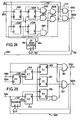
- a servo control system comprises similar parts designated by like reference numerals as in Fig. 2 and is operable with similar signals.
- the servo control system 1 further comprises a position signal producer circuit 600 responsive to the first clock pulse 400c and the digital position signal 500a for producing a position signal 600a representative of the absolute rotational position.
- the position signal 600a is supplied to a control circuit 900.
- the control circuit 900 is identical to the control circuit 100 shown in Fig. 6 except that the position signal 600a is applied to the selector 108 as the second position error signal instead of the output signal 102b of the portion 102L of the counter 102, as shown in Figure 27.
- the position signal producer circuit 600 comprises an up counter 601 identical to the counter 451 of the sensor driver circuit 450 and for counting up the first clock pulse 400c to produce an MSB signal 601 a having the first repetition period.
- the phase difference between the digital position signal 500a and the MSB signal 601 a is proportional to the rotational position of the motor 3.
- the MSB signal 601a and the digital position signal 500a are supplied to an EXOR gate 602 to produce a gate signal 602a whose pulse width is proportional to the phase difference therebetween, i.e., the rotational position.
- the gate pulse 602a is supplied to an AND gate 603 which is supplied with the reference clock pulses 400c.
- the output pulses of the AND gate 603 are supplied to an up counter 604.
- the count signal 604a is set in a register 605 in response to the MSB signal 601a supplied thereto. After the setting the count signal in the register 605, the counter 604 is reset by the MSB signal 601 a passed through a delay circuit 606. Because the pulse width of the gate pulse 602a is proportional to the absolute rotational position of the motor 3, the register 605 supplies the position signal 600a representative of the absolute rotational position every time interval of the first repetition period.
Landscapes
- Engineering & Computer Science (AREA)
- Human Computer Interaction (AREA)
- Manufacturing & Machinery (AREA)
- Physics & Mathematics (AREA)
- General Physics & Mathematics (AREA)
- Automation & Control Theory (AREA)
- Control Of Position Or Direction (AREA)
- Control Of Electric Motors In General (AREA)
Description
- This invention relates to a servo control system responsive in general to a sequence of position commands supplied from an external source for intermittently and controllably driving a motor, with rotation of the motor fed back, to position a movable element at successively commanded positions substantially at rest. More particularly, this invention relates to a digital servo control system for use in a position control or positioning control system for either a carriage of a serial printer of the type known as an impact type in the art or a type wheel, drum, or cylinder carried by the carriage.
- As will be described later with reference to a few of various figures of the accompanying drawing, an impact type serial printer is for use in combination with an electronic digital computer and comprises a carriage, a carriage motor for linearly moving the carriage along a predetermined path in either of two senses along the path, and a position control system for controllably driving the motor so as to successively and intermittently position the carriage at rest at positions commanded by the computer along the path. A rotary type wheel carrying a plurality of type elements is mounted on the carriage together with a type wheel motor for rotating the type wheel in either of two senses of rotation. A similar position control system controllably drives the wheel motor so as to intermittently position the wheel at rest at desired angular or rotational positions commanded also by the computer. Successively selected type elements are thereby placed at a common printing position predetermined relative to the carriage.
- A position control system for controllably positioning a movable element, such as the carriage or the type wheel mentioned above, to a commanded position comprises an increment encoder or position transducer mechanically or otherwise coupled to a motor for the element. It is already known in the art to make the encoder produce a pair of incremental position signals having polarities that vary with a phase difference therebetween in response to every predetermined incremental angle of rotation of the motor. The successive variations in the polarity therefore correspond to a variation in the present or instantaneous angular position of the motor and hence the present linear or angular position of the movable element. The phase difference indicates positive and a negative sense in which the present position is varying. The rate at which the polarities vary is proportional to a present angular velocity of the motor and accordingly the present linear or angular velocity of ference indicates a positive and a negative sense tracted from the commanded signal to provide a position error between the present and the commanded positions. The motor is controlled so as to reduce the position error to zero.
- In US-A-3,954,163 issued to Andrew Gabor, a position control system for an impact serial printer is disclosed wherein either of a motor for a carriage and another motor for a rotary print wheel is controllably driven at first in a velocity control mode and then in a position control mode on moving the movable element intermittently from each commanded position to a next following commanded position. In the velocity control mode, the motor is driven to follow a reference angular velocity selected in consideration of the position error and represented by an analog reference velocity signal. This mode of operation is continued until the element is driven from a commanded position to a point spaced a predetermined length from the next following commanded position. In the position control mode, the motor is driven at a velocity related to an analog position error signal representative of the position error to eventually position the element at rest at next following commanded position.
- The use of analog signals in a servo control system used in such a position control system makes it difficult to achieve excellent results in operation and maintenance. Furthermore, it is rendered difficult to provide a compact servo control system. This means that the servo control system becomes bulky and expensive.
- Shigeru Shimonou, Hiroshi Inada and Tadashi Nomura, assignors to the instant assignee, of whom Hiroshi Inada and Tadashi Nomura are the present joint inventors, have previously proposed position control systems in DE - A - 2 823 571. It was believed that servo control systems used in the previously proposed position control systems were much improved in these respects and, in fact, really is. The previous servo systems, however, are not suitable to position a movable element with very high precision due to use of a photo-encoder as means for producing a position signal, which comprises a rotatable opaque disk connected to the movable element and having azimuthally spaced radial slits or position information pattern, a light source for illuminating the radial slits, and an optical sensor. For positioning with very high precision, the space of the radial slits must be so sufficiently narrowed as to cause the position signal to follow a minute displacement of the movable element. The narrowing in the slit space requires a very high delicate technology for manufacturing the disk, or a large-sized disk. The use of such disk in a photo-encoder causes it to become bulky. The bulky photo-encoder makes it difficult to achieve positioning with very high precision. This means that the servo control system for positioning with very high precision becomes expensive.
- An incremental encoder for producing a phase feedback error signal is disclosed in FR-A 2 381 419 in which the error signal is used for producing a position signal representative of the position of the machine tool. However, the machine tool is simply positioned without using a plurality of control modes.
- It is therefore an object of the present invention to provide a servo control system in which a compact position sensor can be used for producing a position signal in accordance with a minute displacement of a movable element.
- It is another object of this invention to provide a servo control system of the type described, which is operable at high speed and with very high precision.
- It is still another object of this invention to provide a servo control system of the type described, which is simple in structure, compact, and inexpensive.
- It is possible to manufacture essential parts of a servo control system according to this invention as an integrated circuit.
- The objects of the invention are achieved by a control system as defined in
claim 1. - In one embodiment of the invention there is provided a digital servo control system which is responsive to a command signal indicative of a commanded position of a movable element and a phase-modulated position signal having a phase responsive to a predetermined incremental angle of rotation of a motor rotatable with a variable angular velocity to vary the present position of the element, for producing a motor drive signal for controllably driving the motor to position the element at the commanded position. The angular velocity has either of two senses at a time. The 90°-phased sinusoidal waves are applied as sensor drive signal to a position sensor for producing the position signal. The system comprises incremental position pulse producing means responsive to the phase-modulated position signal for producing incremental position pulses representative of a variation in the current position. The system comprises control signal producing means responsive to the command signal and the position pulses for calculating a displacement from the current position to the commanded position and for producing a control signal digitally representative of a reference angular velocity selected for the motor in consideration of the displacement until an instant at which the displacement is reduced in absolute value to a predetermined value, a first positional error determined by the displacement during a prescribed interval of time following the above-mentioned instant, and a second position error having a value increasing in absolute value with relation to the displacement when a predetermined interval of time lapses after the above-mentioned instant. The prescribed interval is not longer in duration than the predetermined interval. The movable element is positioned substantially at the commanded position within the predetermined interval. The system further comprises motor drive signal producing means responsive to the control signal and the position pulses for producing the motor drive signal.
-
- Figure 1 illustrates in blocks a servo control system to which the instant invention is applicable, together with a movable element, a motor, a command signal generator, and a position sensor;
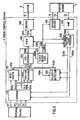
- Figure 2 is a block diagram showing a servo control system according to a first embodiment of this invention, together with the motor, the command signal generator, and the position sensor;
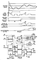
- Figure 3 is a graph showing a few signals for describing the limit cycle that appears in a general digital servo control system;
- Figure 4 is a block diagram of an integrator circuit used in the system depicted in Figure 2;
- Figure 5 is a timing chart diagrammatically showing several signals for describing the operation of the integrator circuit shown in Figure 4;
- Figure 6 is a block diagram of a control circuit used in the system illustrated in Figure 2;
- Figure 7 is a block diagram of a position modifier circuit used in the system illustrated in Figure 2;
- Figures 7A and 7B are graphs showing several signals for describing the operation of the position modifier circuit shown in Figure 7;
- Figure 8 is a block diagram of a clock generator circuit used in the system shown in Figure 2;
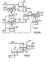
- Figure 9 is a block diagram of a velocity detector circuit used in the system illustrated in Figure 2;
- Figure 10 is a block diagram of an add-subtractor circuit used in the system depicted in Figure 2;
- Figure 11 is a block diagram of a pulse width modulator circuit used in the system shown in Figure 2;
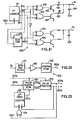
- Figure 12 is a block diagram of a driver circuit used in the system illustrated in Figure 2;
- Figure 13 is a block diagram of another driver circuit for use in the system shown in Figure 2;
- Figure 14 is a block diagram of still another driver circuit for use in the system shown in Figure 2;
- Figure 15 shows in a schematic side view a motor and a position sensor for use in combination with the system illustrated in Figure 2;
- Figure 16 shows in a schematic equivalent circuit diagram the position sensor shown in Figure 15;
- Figure 17 is a block diagram of a sensor driver circuit used in the system illustrated in Figure 2;
- Figure 18 is a timing chart showing several signals for describing the operation of the sensor driver circuit shown in Figure 17;
- Figure 19 is a block diagram of another sensor driver circuit for use in the system shown In Figure 2;
- Figure 20 is a timing chart showing several signals for describing the operation of the sensor driver circuit shown in Figure 19;
- Figure 21 is a block diagram of still another sensor driver circuit for use in the system shown in Figure 2;
- Figure 22 is a block diagram of an amplifier used in the system illustrated in Figure 2;
- Figure 23 is a block diagram of an incremental position pulse producer circuit used in the system shown in Figure 2;
- Figure 24 is a block diagram of another incremental position pulse producer circuit for use in the system shown in Figure 2;
- Figure 25 is a block diagram of still another incremental position producer circuit for use in the system shown in Figure 2;
- Figure 26 is a block diagram of a servo control system according to a second embodiment of this invention, together with the motor, the command signal generator, and the position sensor;
- Figure 27 is a block diagram of a control circuit used in the system illustrated in Figure 26; and
- Figure 28 is a block diagram of a position signal producer circuit used in the system shown in Figure 26.
- It is to be noted at outset that signals and lines for transmitting the respective signals are often designated by the same reference characters in the following description.
- Referring to Figure 1, a servo control system to which the present invention is applicable is for use in a position control system accompanied by a movable element 7, such as a carriage of a serial printer of the impact type, and a
motor 3 for controllably driving an axle shaft thereof with a variable angular velocity. Merely for convenience of illustration, the axle is depicted as passing through themotor 3. The axle is coupled to the element 7 by means of a driving pulley 5 fixed to the axle and a wire orbelt 6 is driven by the driving pulley 5. Themotor 3 thus controllably varies the present or instantaneous position of the element 7. The position control system is for use in combination also with a command signal generator orexternal source 4, such as an electronic digital computer, for producing a digital command signal indicative in general of successively commanded positions of the element 7. It is possible to assume without loss of generality that the motor axle is kept in a predetermined direction. The "angular velocity" as called herein is therefore specified only by its magnitude and sense. It is to be remembered furthermore that the expressions are used herein such that the "motor" 3 is rotatable in one or the other sense at a time and the like. - Further referring to Figure 1, the position control system comprises a
servo control system 1 and a position sensor orposition transducer 2, which is supplied withsensor driving signals motor 3 to produceposition signal 2a and supplies the same to theservo control system 1. The command signal for each commanded position or end point is produced by thecommand signal generator 4 in response to a new-data request signal 1 d supplied thereto from theservo control system 1 in the manner described later and consists of asense signal 4a and adistance signal 4b, which are supplied to theservo control system 1. Thedistance signal 4b is usually representative of a distance of the end point from the next previous commanded position or start point and consists of a predetermined number of bits, such as eleven bits. Thesense signal 4a indicates a positive and a negative sense, such as counterclockwise and clockwise senses, of rotation of themotor 3 at a time and may be an additional bit, such as a twelfth bit, of the command signa) 4a-4b. Thecommand signal 4a-4b is set in theservo control system 1 by a set signal 4c supplied from thecommand signal 4a-4b and theposition signal 2a, theservo control system 1 supplies amotor drive signal 1 c to the motor to make the same move the movable element 7 to the end point as will be described hereunder. - Referring to Figure 2, a
servo control system 1 according to a first embodiment of this invention comprises aclock generator circuit 400 for generating several clock pulse sequences, such as an integrationclock pulse sequence 400a, a pulse width modulation (PWM)clock pulse sequence 400b, a pair ofreference pulse sequences clock pulse sequence 400e. The repetition frequencies or clock rates of the respectiveclock pulse sequences 400a through 400e will be exemplified later. Let it now be presumed that thesense signal 4a indicates the positive sense of rotation of themotor 3. When produced, the sense and the distance signals 4a and 4b are stored in acontrol circuit 100 in response to the set signal 4c. Thecontrol circuit 100 produces amode signal 100a that indicates at first the velocity control mode described in the preamble of the present specification. Thecontrol circuit 100 produces also adigital control signal 100b representative of one of a plurality of reference angular velocities predetermined for themotor 3 that is selected in consideration of the position error, mentioned also hereinabove, now given by thedistance signal 4b by itself. Thecontrol signal 100b is supplied to aposition modifier circuit 650 and anintegrator circuit 150, of which thelatter circuit 1 50 is primarilly for integrating theintegration clock pulse 400a. Theintegrator circuit 150, however, keeps anintegrator output signal 150a thereof at zero in . the velocity control mode rather than actually carrying out the integration. Theposition modifier circuit 650, responsive to themode signal 100a indicative of the velocity control mode, supplies thecontrol signal 100b as it is through aline 650a to an add-subtractor circuit 200. The add-subtractor circuit 200 produces analgebraic sum signal 200a that is representative at present of the selected reference angular velocity as will become clear as the description proceeds. By the use of thePWM clock pulse 400b, a pulse width modulator (PWM)circuit 250 carries out pulse width modulation of thealgebraic sum signal 200a to deliver a modulating output signal alternatively to two modulator output leads 250a and 250b. The signals supplied to the individual leads 250a and 250b will herein be called positive and negative modulating output signal, respectively. Supplied with the positive and the negativemodulating output signals driver circuit 300 makes themotor drive signal 1c drive themotor 3 in the positive sense with its present angular velocity increased towards the selected reference angular velocity. - As soon as the
motor 3 begins to rotate in the positive sense, theposition sensor 2, which is supplied from asensor driver circuit 450 with thesensor driving signals position signal 2a. Theposition signal 2a is supplied to anamplifier 500 to provide adigital position signal 500a. Thedigital position signal 500a is supplied to an incremental positionpulse producer circuit 550, which is supplied with first and second referenceclock pulse sequences positive position pulses 550a. The positionpulse producer circuit 550 produces pulses of a negativeposition pulse sequence 550b when themotor 3 is rotating in the negative sense. Responsive to thepositive position pulses 550a and the samplingclock pulse sequence 400e, avelocity detector circuit 350 produces avelocity signal 350a representative of the present angular velocity. In thecontrol circuit 100, the pulses of the positiveposition pulse sequence 550a are subtracted from thedistance signal 4b. The difference represents the position error. It is possible to understand that the calculation is for deriving a displacement from the present position of themotor 3 or the movable element 7 to the commanded position thereof. Inasmuch as the displacement has a predetermined direction, the displacement is defined by a magnitude and either of a positive or negative sense. The magnitude is given by the difference. As will become clear as the description proceeds, the sense is given by thesense signal 4a. With reference to the position error, the reference angular velocity is stepwise reduced in general. In the meantime, thevelocity signal 350a is subtracted in the add-subtractor circuit 200 from the reference angular velocity to make the present angular velocity of themotor 3 follow the reference angular velocity. Thevelocity detector circuit 350 and the add-subtractor circuit 200 thus provide velocity feedback. - When the displacement calculated in the
control circuit 100 decreases in absolute value to a predetermined value, themode signal 100a begins to indicate the position control mode. Thedigital control signal 100b now represents the position error instead of the reference angular velocity. As will become clear later, the position error has either a positive or a negative sign in the position control mode. The sense of displacement is given by the sign. Theintegrator circuit 150 does not yet carry out the integration. Thevelocity detector circuit 350 and the add-subtractor circuit 200 provide velocity feedback, which now serves as damping. Theintegrator circuit 150 beings to carry out the integration a predetermined interval of time after the instant at which themode signal 1 00a is switched to indicate the position control mode for suppressing the limit cycle as it will presently become clear. It may be mentioned here that themotor 3 is driven within the predetermined interval substantially to the commanded position. The predetermined interval may, for example, be several milliseconds long. - Turning to Figure 3, let it be surmised that the movable element 7 and consequently the
motor 3 should be positioned at a commandedposition 10 shown in the top row of the figure. Because of the digital operation, theposition sensor 2 specifies the commandedposition 10 as a dead band orzone 11 having a width inversely proportional to the number of the positive or thenegative position pulses pulse producer circuit 550 per one complete rotation of the motor. When the position error decreases as exemplified in the left end portion of the top row at 12, themotor 3 is decelerated towards a stop. Thevelocity signal 350a is very small. Thedigital control signal 100b representative of the position error of the values +2 and +1 is therefore successively fed back in approximation to themotor 3. When the position error is further reduced into thedead zone 11, themotor 3 receives no force from theservo control system 1. Due to the inertia, the position error becomes -1 and then tends to transiently oscillate between +1 and -1 before themotor 3 is positioned eventually at rest at the commandedposition 10. If an external force is applied to themotor 3 during the transient oscillatory rotation thereof in, for example, the positive sense indicated at 13 from the motor brushes (not shown) and/or the movable element driving mechanism comprising thewire 6, the transient oscillation lasts for a relatively long time at least between +1 and 0 as depicted at 13' with a peak-to--peak value approximately equal to two in terms of the number of pulses of the positive or thenegative position pulses - Referring now to Figure 4, an example of the
integrator circuit 150 is supplied with thestop signal 100c, which is switched from a logic "0" level to a logic "1" level a predetermined interval of time after the instant at which themode signal 100a is switched to indicate the position control mode, i.e., from the logic "0" level to the logic "1" level. Thestop signal 100c of logic "0" is supplied through aninverter 151 to a reset input terminal R of anintegration counter 152 as a logic "1" signal and directly to one input each of first and second three-input ANDgates mode signal 100a indicates the velocity control mode and during the predetermined time interval. In the meanwhile, thecounter 152 is kept in the reset state to maintain theintegrator output signal 150a zero. - In Figure 4, a
first detector 155 supplies a logic "1" signal to a second input of the first ANDgate 153 in response to thedigital control signal 100b when thesignal 100b represents a number equal to +1 or greater. Likewise, asecond detector 156 delivers a logic "1" signal to a second input of the second ANDgate 154 when thedigital control signal 100b is representative of a number equal to -1 or less. The ANDgates integration clock pulses 400a are supplied to a third input each of the ANDgates counter 152 counts up and down theintegration clock pulses 400a supplied to count up and down terminals U and D thereof through the enabled first and second ANDgates integrator output signal 150a an increasing or decreasing value rather than zero. Let the most significant bit (MSB) of thedigital control signal 100b serve as a sign bit for indicating the sign of the position error in the position control mode. Thefirst detector 155 may comprise an AND gate responsive to the most significant bit of thedigital control signal 100b and an OR'ed output of thesignal 1 OOb except the most significant bit. Thesecond detector 156 may comprise an inverter for the most significant bit. Theintegrator circuit 1 50 thus carries out integration of the position error in the sense or sign that the position error has. - Referring to Figure 5, it is now presumed that the
servo control system 1 is switched from the velocity control mode to the position control mode when the absolute value of the displacement decrease from four to three. Thedigital control signal 100b now indicates the position error that decrease as depicted at 21 along the top row. Themode signal 100a is switched from the logic "0" level to the logic "1" level as shown in the next row. When a predetermined interval oftime 22 lapses after themode signal 100a is switched to the logic "1" level, thestop signal 100c is switched to a logic "1" level. In the meantime, the position error is reduced to zero. The limit cycle, however, appears as depicted at 23 in the top row. Thefirst detector 155 intermittently produces logic "1" " signals 24 to enable the first three-input ANDgate 153. Theintegration clock pulses 400a therefore supplied to the count up terminal U of theintegration counter 152 as shown at 25. Theintegrator output signal 150a is thus a stepwise rising level. The limit cycle is suppressed when the external force is balanced by the torque produced by themotor 3 in response to theintegrator output signal 150a of a certain level exemplified at 25'. It is thereby possible to position the movable element 7 quickly at the commandedposition 10. - Turning to Figure 6, an example of the
control circuit 100 is supplied with thesense signal 4a, thedistance signal 4b and the set signal 4c from thecommand signal generator 4 in the velocity control mode. Responsive to the set signal 4c, thesense signal 4a and thedistance signal 4b are set in aregister 101 and oneportion 102M (more-significant-bit parts) of adown counter 102 as an initial count, respectively. Thedown counter 102, which is supplied with theincremental position pulses gate 103, counts down the initial count to produce first and second position error signals 102a and 102b. A combination of thesense signal 4a and the first and second position error signals 102a and 102b is used to specify an address of amemory 104 in which are stored several reference angular velocity signals. Addressed by thesesignals memory 104 supplies aline 104a with a selected one of the reference velocity signals. When thedistance signal 4b is an eleven-bit signal, i.e., theportion 102M of thedown counter 102 is composed of a eleven-bit counter, the other portion 102L (less-significant-bit parts) of thedown counter 102 is preferably a three-bit counter that produces the secondposition error signal 102b representative in the position control mode of the magnitude of the displacement in terms of the number of the positive or thenegative position pulses position pulses position error signal 102a represents the magnitude of the displacement in terms of the unit for the least moving distance, and the secondposition error signal 102b represents the displacement in a range of the least moving distance. - In Figure 6, the set signal 4c is supplied to a reset terminal R of a flip-
flop circuit 105, which is also supplied at a set terminal S with a zero- detect signal 104b produced by thememory 104 when thefirst position signal 102a represents zero, to make themode signal 100a indicate the velocity and the position control modes by a logic "0" (low) and a logic "1" (high) level, respectively. Afirst timer 106 composed of amonostable multivibrator 1061 and an ANDgate 1062 produces thestop signal 100c a predetermined interval of time 22 (Fig. 5) after the instant at which themode signal 100a is switched from the logic "0" level (velocity control mode) to the logic "1" level (position control mode). Asecond timer 107 identical to thefirst timer 106 except for the time constant for the monostable multivibrator produces the new-data request signal 1 d a prescribed interval of time after the above-mentioned instant. Supplied with themode signal 100a indicative of the velocity control mode, aselector 108 pro- .duces the reference angular signal as thedigital control signal 100b. When themode signal 100a indicates the position control mode, theselector 108 produces the secondposition error signal 102b as thedigital control signal 100b. - Referring to Figure 7, an example of the
position modifier circuit 650 comprises aselector 651, which is supplied with themode signal 100a and thedigital control signal 100b. When themode signal 100a indicates the velocity control mode, theselector 651 produces thedigital control signal 100b at theline 650a. When themode signal 100a is switched to indicate the position control mode, theselector 651 supplies anoutput signal 652a supplied from amemory 652, which is supplied with the mode,signal 100a, thedigital control signal 100b and thestop signal 100c as address data thereof. Addressed by thesesignals memory 652 supplies a first and a second modified signals as depicted in Figures 7A and 7B when thestop signal 100c is logic "0" level and logic "1" level, respectively. In other words, the first modified position signal having no dead zone is supplied from thememory 652 through theselector 651 to theline 650a during the predetermined interval of time 22 (Fig. 5). When thestop signal 100c is switched from the logic "0" level to the logic "1" level, thememory 652 supplies theline 652a the second modified position signal having thedead zone 11, which is passed through theselector 651 to theline 650a. - Turning to Figure 8, the
clock generator circuit 400 preferably comprises astandard clock generator 401 for generating a standard clock pulse sequence at a sufficiently high clock rate. Acounter 402 divides the frequency of the standard clock pulse sequence to provide the integrationclock pulse sequence 400a. The standard clock pulse sequence is used as the PWMclock pulse sequence 400b. The standard clock pulse sequence is supplied to a referenceclock pulse producer 403 composed of a flip-flop circuit and two AND gates to provide the first and second referenceclock pulse sequences counter 402 further frequency divides the standard clock pulse sequence to provide a low-rate clock pulse sequence, which is shaped by ashaping circuit 404 into the samplingclock pulse sequence 400e. By way of example, the clock rate of the standard clock pulse sequence and accordingly the PWM and the referenceclock pulse sequences 400b through 400c is 1 MHz. Those of the integration and the samplingclock pulse sequences - Referring to Figure 9, an example of the
velocity detector circuit 350 comprises an up-down counter 351 for counting up and down the positive andnegative position pulses register 352. Thesampling clock pulses 400e are supplied to a set input terminal S of theregister 352 directly and to a reset input terminal R of thecounter 351 through adelay circuit 353. When each of thesampling clock pulses 400e appears, the count signal is set or registered in theregister 352 to be produced therefrom as thevelocity signal 350a. lm- mediately thereafter, thecounter 351 is reset. Thevelocity signal 350a thus represents the number of the positive ornegative position pulses pulse producer circuit 550 within an interval of time determined by the samplingclock pulse sequence 400e. - Referring to Figure 10, an example of the add-
subtractor circuit 200 comprisesmemories mode signal 100a indicative of the velocity control mode and the position control mode, respectively. These factors are supplied tomultipliers multiplier 204 multiplies the reference angular velocity signal and the position error signal supplied through theline 650a by the factors KS1 and KP in the velocity and the position control modes, respectively. Anadder 207 adds theintegration output signal 150a to the multiplied signal derived from themultiplier 204. Themultiplier 205 multiplies thevelocity signal 350a by the factors KS2 and KP2 in the velocity and the position control modes, respectively. Asubtractor 208 subtracts the multipliedvelocity signal 205a of themultiplier 205 from anoutput signal 207a of theadder 207. An output signal 208a of thesubtractor 208 is supplied to themultiplier 206 and multiplied by the factors KS3 and KP3 in the velocity and the position control modes, respectively, to provide thealgeraic sum signal 200a. - Because the
integrator output signal 150a is maintained at zero when the stop signal is the logic "0" level, the multiplied signal 204a from themultiplier 204 is supplied to thesubtractor 208 as it is. Therefore, during the time interval of the velocity control mode and thepredetermined time interval 22, i.e., during time that the stop signal is the logic "0" level, the velocity signal is subtracted from the reference angular velocity signal or the position error signal. During the time interval of the position control mode except for thetime interval 22, the position error signal is added to the integration output signal and the velocity signal is subtracted from the added signal. - Referring to Figure 11, an example of the
PWM circuit 250 comprises acounter 251 for counting thePWM clock pulses 400b. When thecounter 251 has counted up to its full count, it is reset to zero and the cycle is repeated to continue counting theclock pulses 400b. The resetting cycle may, for example, be 20KHz. It is readily possible to make the count signal vary between a negative and a positive values having a substantially equal absolute value. Acomparator 252 compares thealgebraic sum signal 200a supplied to a signal input terminal A thereof with the oscillating count signal supplied to a reference input terminal B. When thealgebraic sum signal 200a is (a) not less than and is (b) less than the oscillating count signal 8, thecomparator 252 gives the logic "1" (high) level to the positive and thenegative output signals comparator 252 thus gives the logic "1" level to each of the positive and thenegative output signals counter 251. When thealgebraic sum signal 200a has a positive level, the duration of the high level of thepositive output signal 250a is longer in proportion to the positive level than the duration during which thenegative output signal 250b is given the high level. Theleads algebraic sum signal 200a. - Referring to Figure 12, an example of the
driver circuit 300 comprises first andsecond driving transistors positive output signal 250a is delivered to anNPN transistor 303 through agate 304. Thenegative output signal 250b is supplied to aPNP transistor 306 through aninverter gate 307. When thepositive output signal 250a is given the high level, the NPN and thePNP transistors second driving transistors negative output signal 250b is rendered high, the point of connection is given a power of a voltage nearly equal to the negative power supply voltage -ES. The power derived at the point of connection thus has an average voltage proportional to thealgebraic sum signal 200a and is used as themotor drive signal 1c. It should be noted that themotor 3 has an electrical time constant that gives rise to a low-pass phenomenon and defines cutoff frequency. With the clock rate of thePWM clock pulses 400b selected sufficiently higher than the cutoff frequency as exemplified above, it is possible to render the electric current supplied to themotor 3 proportional to thealgebraic sum signal 200a. - Referring to Figure 13, another example of the
driver circuit 300 is operable in a push-pull fashion and comprises first and second additional drivingtransistors positive output signal 250a is supplied to an additional PNP transistor 313 through thegate 304 and aninverter 314. Thenegative output signal 250b is supplied to anadditional transistor 316 through theinverter gate 307 and anotherinverter 317. When thepositive output signal 250a is given the high level, thefirst driving transistors second driving transistors motor drive signal 1c thereby produced betweenconnection negative output signal 250b is rendered high, themotor drive signal 1 c has a voltage near -2ES. The illustrateddriver circuit 300 is therefore capable of raising the gain of theservo control system 1 and thereby improving the control characteristics thereof. - Referring to Figure 14, still another example of the
driver circuit 300 is specifically adapted to amotor 3 that is subject to demagnetization when the motor drive current exceeds a certain limit. The illustratedcircuit 300 comprises similar parts designated again by like reference numerals as in Fig. 12 and, in addition thereto, aresistor 326 interposed between theconnection 322 serving as a return conductor for the motor drive current and a point of common potential for detecting the current flowing through themotor 3. The voltage developed across theresistor 326 is compared with a reference voltage selected for the current limit in either of positive andnegative comparators 327 and 328. When the motor current is for the positive sense of rotation and tends to exceed the limit, thepositive comparator 327 produces a logic "1" signal. The output signals of thecomparators 327 and 328 serve to close or disable thegates gate 329 and thereby prevent the motor current from exceeding the limit. - Referring to Figure 15, the
position sensor 2 attached to themotor 3 comprises astator 30 attached to the motor frame, arotor 31 mechanically coupled to themotor axle 32 to be rotatable with themotor 3, and arotary transformer 33. Thestator 30 comprises, as shown in Fig. 16, a first and a second primary coils orstator windings sensor driving signals rotor 31 comprises a secondary coil or a rotor winding 31 a from which an induced signal is obtained by the electromagnetic induction. The winding period of the rotor winding 31 a is equal to that of the stator winding 30a or 30b. Theposition sensor 2 may be composed of the rotary "Inductosyn" (trademark) as described in the U.S. Patent No. 3,191,010. In Fig. 16, thewindings - The
stator windings sensor driving signals rotor 31 or themotor axle 32. The induced phase modulated signal is supplied through therotary transformer 33 to theservo system 1 as theposition signal 2a. - Referring to Figure 17, an example of the
sensor driver circuit 450 comprises a up counter 451 for counting up thereference clock pulses 400c. The up counter 451 supplies the most- significant-bit signal and the secondary- significant-bit signal as the first MSB signal 451 a and the second MSB signal 451 b tolines up counter 451 is so selected that the repetition period, i.e., the pulse rate of the MSB signal 451 a is equal to the first repetition period. The first MSB signal 451 a is supplied to a data input terminal D of a flip-flop circuit 452 and sampled by the second MSB signal 451 b supplied to a clock input terminal C to provide anoutput signal 452a having a phase different from that of the first MSB signal 451 a by 90°, as shown in Fig. 18. Thesignals pass filter circuits - Referring to Figure 19, another example of the
sensor driver circuit 450 comprises theup counter 451 and a read-only-memory (ROM) 455 responsive to the count signal as address data for producing a first and a seconddigital data digital data analog converter circuits sinusoidal waves sinusoidal waves pass filter circuits sensor driving signals - Referring to Figure 21, the still another example of the
sensor driver circuit 450 comprises the up counter 451 for supplying the first, the second and the third MSB signals to thelines gates EXOR gates gates transistors line 1 a throughresistors line 1a is connected throughcapacitor 464 to a positive power supply of +5V. Theresistor 462 has a resistance of R, while theresistor 463 has 3R. With counting thereference clock pulses 400c, theline 1 a leads the sinusoidal wave having the first repetition period. - The first MSB signal 451 a is shifted by 90° by a flip-
flop circuit 464, which is supplied at a clock input terminal C with the second MSB signal 451 b. The 90°-phased signal 464a is supplied toEXOR gates line 1b supplies the sinusoidal wave phase-shifted by 90° with respect to thesinusoidal wave 1a. - Referring to Figure 22, an
amplifier circuit 500 comprises a band-pass filter 501 having a center frequency corresponding to the first repetition period and for suppressing noise components. The output signal of the band-pass filter 501 is supplied through anamplifier 502 to acomparator 503. Thecomparator 503 produces thedigital position signal 500a. - Referring to Figure 23, the incremental position
pulse producer circuit 550 comprises an up-down counter 551 for counting up the first referenceclock pulse sequence 400c. The bit-number of thecounter 551 is equal to that of thecounter 451 used in thesensor driver circuit 450, whereby thecounter 551 supplies anMSB signal 551a a having the first repetition period. - The
digital position signal 500a phase-modulated by the rotational position of themotor 3 is supplied to aphase comparator 552 and phase-compared with the MSB signal 551 a a supplied from thecounter 551 thereto. When the phase of thedigital position signal 500a with reference to that of the MSB signal 551 a is shifted by a value not less than a predetermined value, for example, one repetition period of the secondreference clock pulse 400d, thecomparator 552 supplies the logic signal tolines 552a and 552b in accordance with a phase advance and phase lag, respectively. The output signals 552a and 552b are supplied to apulse producer 553 for producing theincremental position pulses incremental position pulse 550a is supplied through an ORgate 554 to the up terminal U of thecounter 551 to count up the count signal by one. The negativeincremental position pulse 550b is supplied to the down terminal D of thecounter 551 to count down the count signal by one. - As understood from the above, when the
motor 3 is stopped, the phase of the MSB signal 551 a is usually coincident with that of thedigital position signal 500a, whereby no incremental position pulse is produced. When themotor 3 is rotating, the positive or negativeincremental position pulse motor 3 is rotated by a predetermined rotational angle. - Referring to Figure 24, the
phase comparator 552 is composed of four flip-flop circuits 5521 to 5524, and five ANDgates 5525 to 5529. Thedigital position signal 500a is sampled by the secondreference clock pulse 400d in the flip-flop circuits gates gates reference clock pulse 400d in the flip-flop circuits 5523 and 4424 and the ANDgate 5527 produces a gate signal 5527a, which. is supplied to the ANDgates - When the
motor 3 moves in the positive sense, thedigital position signal 500a is phase- advanced from the MSB signal 551 a, whereby the positiveincremental position pulse 550a is generated. The positiveincremental position pulse 550a is supplied through the up terminal U of thecounter 551 to count up by one, whereby the MSB signal becomes in phase with thedigital position signal 500a. When become inphase, no incremental position pulse is produced. When themotor 3 is again moved in the positive sense, and the phase difference between thedigital position signal 500a and the MSB signal 551 a exceeds the predetermined value, i.e., the time interval equal to one repetition period of thesecond clock pulse 400d, the positiveincremental position pulse 550a is again produced. Conversely, when themotor 3 is moved in the negative sense, the negativeincremental position pulse 550b is produced and supplied to the down terminal D of thecounter 551 to count down by one, whereby the MSB signal 551 a becomes in phase with thedigital position signal 500a. - Referring to Figure 25, the
MSB signal 551a a is sampled by the firstreference clock pulse 400c in flip-flop circuits first clock pulse 400c. Thedigital position signal 500a is sampled by the secondreference clock pulse 400d in flip-flop circuits output signals 558a and 559a, respectively. The output signals 559a and 558a are sampled by the output signal 555a in flip-flop circuits gates gates incremental position pulses motor 3 is moved in the positive and negative senses, respectively. - It is possible to install an additional flip-flop circuit between the flip-
flop circuits - Turning to Figure 26, a servo control system according to a second embodiment of this invention comprises similar parts designated by like reference numerals as in Fig. 2 and is operable with similar signals. The
servo control system 1 further comprises a positionsignal producer circuit 600 responsive to thefirst clock pulse 400c and thedigital position signal 500a for producing aposition signal 600a representative of the absolute rotational position. Theposition signal 600a is supplied to acontrol circuit 900. Thecontrol circuit 900 is identical to thecontrol circuit 100 shown in Fig. 6 except that theposition signal 600a is applied to theselector 108 as the second position error signal instead of theoutput signal 102b of the portion 102L of thecounter 102, as shown in Figure 27. - Finally referring to Figure 28, the position
signal producer circuit 600 comprises an up counter 601 identical to thecounter 451 of thesensor driver circuit 450 and for counting up thefirst clock pulse 400c to produce anMSB signal 601 a having the first repetition period. The phase difference between thedigital position signal 500a and the MSB signal 601 a is proportional to the rotational position of themotor 3. TheMSB signal 601a and thedigital position signal 500a are supplied to anEXOR gate 602 to produce agate signal 602a whose pulse width is proportional to the phase difference therebetween, i.e., the rotational position. Thegate pulse 602a is supplied to an ANDgate 603 which is supplied with thereference clock pulses 400c. The output pulses of the ANDgate 603 are supplied to an upcounter 604. The count signal 604a is set in aregister 605 in response to theMSB signal 601a supplied thereto. After the setting the count signal in theregister 605, thecounter 604 is reset by the MSB signal 601 a passed through adelay circuit 606. Because the pulse width of thegate pulse 602a is proportional to the absolute rotational position of themotor 3, theregister 605 supplies theposition signal 600a representative of the absolute rotational position every time interval of the first repetition period.
Claims (9)
Applications Claiming Priority (4)
| Application Number | Priority Date | Filing Date | Title |
|---|---|---|---|
| JP5269479A JPS5951007B2 (en) | 1979-04-27 | 1979-04-27 | position detection device |
| JP52694/79 | 1979-04-27 | ||
| JP16326679A JPS56132612A (en) | 1979-12-14 | 1979-12-14 | Digital positioning controller |
| JP163266/79 | 1979-12-14 |
Publications (2)
| Publication Number | Publication Date |
|---|---|
| EP0020024A1 EP0020024A1 (en) | 1980-12-10 |
| EP0020024B1 true EP0020024B1 (en) | 1983-06-22 |
Family
ID=26393337
Family Applications (1)
| Application Number | Title | Priority Date | Filing Date |
|---|---|---|---|
| EP80301369A Expired EP0020024B1 (en) | 1979-04-27 | 1980-04-25 | Servo control system operable on digital basis |
Country Status (3)
| Country | Link |
|---|---|
| US (1) | US4313074A (en) |
| EP (1) | EP0020024B1 (en) |
| DE (1) | DE3063844D1 (en) |
Families Citing this family (18)
| Publication number | Priority date | Publication date | Assignee | Title |
|---|---|---|---|---|
| GB2110852B (en) * | 1981-10-19 | 1985-02-13 | Canon Kk | Printer |
| JPS58189706A (en) * | 1982-04-28 | 1983-11-05 | Fanuc Ltd | Speed compensation system of speed command system |
| US4494052A (en) * | 1982-08-05 | 1985-01-15 | Rca Corporation | DC Motor servo system |
| GB2147123B (en) * | 1983-08-04 | 1987-06-03 | Canon Kk | Motor control device |
| JP2572564B2 (en) * | 1983-08-22 | 1997-01-16 | 株式会社 エスジー | Electric motor positioning controller |
| JPS6352694A (en) * | 1986-08-19 | 1988-03-05 | Sony Corp | Digital servo-circuit |
| US4849680A (en) * | 1986-11-07 | 1989-07-18 | Kabushiki Kaisha Empire Airport Service | Encoder |
| JPH03110607A (en) * | 1989-09-26 | 1991-05-10 | Fanuc Ltd | Servo motor control system |
| DE69109593T2 (en) * | 1990-09-21 | 1995-11-23 | Canon Kk | Recorder. |
| US5451852A (en) * | 1993-08-02 | 1995-09-19 | Gusakov; Ignaty | Control system having signal tracking window filters |
| JP3280556B2 (en) * | 1995-11-08 | 2002-05-13 | カルソニックカンセイ株式会社 | Positioning device |
| US6064171A (en) * | 1999-06-11 | 2000-05-16 | Lexmark, International, Inc. | Host based stepper motor phase controller and method therefor |
| JP2004030401A (en) * | 2002-06-27 | 2004-01-29 | Nippon Sogo Seisaku Kk | Constant-speed control and positioning control method for extremely highly stable rotary system adopting atomic frequency standard for reference oscillator for machine control |
| JP4094389B2 (en) * | 2002-09-10 | 2008-06-04 | 株式会社小糸製作所 | Vehicle headlamp device |
| US7139621B2 (en) * | 2004-12-16 | 2006-11-21 | Caterpillar Inc | Floating deadband control |
| US7999244B2 (en) * | 2007-12-18 | 2011-08-16 | Microvision, Inc. | MEMS devices and related scanned beam devices |
| US8109197B1 (en) | 2008-06-18 | 2012-02-07 | Arnold Peterson | Hydraulic control system and method |
| US8069772B1 (en) * | 2008-06-18 | 2011-12-06 | Arnold Peterson | Systems and methods for controlling hydraulic actuators |
Citations (2)
| Publication number | Priority date | Publication date | Assignee | Title |
|---|---|---|---|---|
| US3954163A (en) * | 1970-03-30 | 1976-05-04 | Xerox Corporation | High speed printer with intermittent print wheel and carriage movement |
| DE2823571A1 (en) * | 1977-05-31 | 1979-03-01 | Nippon Electric Co | DEVICE FOR POSITION CONTROL |
Family Cites Families (5)
| Publication number | Priority date | Publication date | Assignee | Title |
|---|---|---|---|---|
| US3519904A (en) * | 1965-05-28 | 1970-07-07 | Gen Electric | Square wave excitation of feedback devices |
| US3728607A (en) * | 1968-02-29 | 1973-04-17 | Gen Electric | Phase analog numerical control system employing a laser digitized position feedback |
| CA1125918A (en) * | 1977-02-18 | 1982-06-15 | Francis A. Fluet | Incremental phase-tracking position measuring system |
| GB2026205B (en) * | 1978-06-09 | 1983-02-16 | Nippon Electric Co | Digital servo control system |
| US4226546A (en) * | 1978-12-06 | 1980-10-07 | Sci Systems, Inc. | Printer control system |
-
1980
- 1980-04-25 DE DE8080301369T patent/DE3063844D1/en not_active Expired
- 1980-04-25 EP EP80301369A patent/EP0020024B1/en not_active Expired
- 1980-04-28 US US06/144,131 patent/US4313074A/en not_active Expired - Lifetime
Patent Citations (2)
| Publication number | Priority date | Publication date | Assignee | Title |
|---|---|---|---|---|
| US3954163A (en) * | 1970-03-30 | 1976-05-04 | Xerox Corporation | High speed printer with intermittent print wheel and carriage movement |
| DE2823571A1 (en) * | 1977-05-31 | 1979-03-01 | Nippon Electric Co | DEVICE FOR POSITION CONTROL |
Also Published As
| Publication number | Publication date |
|---|---|
| US4313074A (en) | 1982-01-26 |
| EP0020024A1 (en) | 1980-12-10 |
| DE3063844D1 (en) | 1983-07-28 |
Similar Documents
| Publication | Publication Date | Title |
|---|---|---|
| US4313074A (en) | Servo control system operable on digital basis | |
| US4259626A (en) | Servo control system operable on digital basis with limit cycle suppressed | |
| US4228396A (en) | Electronic tachometer and combined brushless motor commutation and tachometer system | |
| US4447771A (en) | Control system for synchronous brushless motors | |
| US4739346A (en) | Drive system and method for ink jet printer | |
| EP0157202A1 (en) | Digital PWMed pulse generator | |
| CA1270542A (en) | Method and apparatus for correcting resolver errors | |
| US4623831A (en) | Rotor position sensing apparatus for motors | |
| US4240014A (en) | Precision motor speed control system | |
| GB2145297A (en) | Brushless motor control | |
| US4008425A (en) | Motor servo system with multiplier means to drive and servo the motor | |
| CA1176698A (en) | Microprocessor controlled micro-stepping chart drive | |
| US4734633A (en) | Speed control apparatus for a synchronous motor | |
| US4837493A (en) | System for driving drum | |
| US4559485A (en) | Control systems for AC induction motors | |
| US3596162A (en) | Speed control system with comparison of a sawtooth wave with a reference level | |
| GB2040467A (en) | Position controller | |
| US4266176A (en) | Induction motor slip frequency controller | |
| EP0077403B1 (en) | Speed detecting device | |
| US4438398A (en) | Position detecting signal generator | |
| US5004965A (en) | Brushless motor with torque compensation | |
| US4426608A (en) | Stepping motor control system | |
| US4476420A (en) | Circuit arrangement for synthesizing a sinusoidal position signal having a desired phase and high-resolution positioning system making use of the circuit arrangement | |
| CA1189598A (en) | Printer | |
| EP0133580A1 (en) | Permanent magnet synchronous motor control system |
Legal Events
| Date | Code | Title | Description |
|---|---|---|---|
| PUAI | Public reference made under article 153(3) epc to a published international application that has entered the european phase |
Free format text: ORIGINAL CODE: 0009012 |
|
| AK | Designated contracting states |
Designated state(s): DE FR GB IT NL |
|
| 17P | Request for examination filed |
Effective date: 19810603 |
|
| ITF | It: translation for a ep patent filed | ||
| GRAA | (expected) grant |
Free format text: ORIGINAL CODE: 0009210 |
|
| AK | Designated contracting states |
Designated state(s): DE FR GB IT NL |
|
| REF | Corresponds to: |
Ref document number: 3063844 Country of ref document: DE Date of ref document: 19830728 |
|
| ET | Fr: translation filed | ||
| RAP2 | Party data changed (patent owner data changed or rights of a patent transferred) |
Owner name: NEC CORPORATION |
|
| PLBE | No opposition filed within time limit |
Free format text: ORIGINAL CODE: 0009261 |
|
| STAA | Information on the status of an ep patent application or granted ep patent |
Free format text: STATUS: NO OPPOSITION FILED WITHIN TIME LIMIT |
|
| 26N | No opposition filed | ||
| ITPR | It: changes in ownership of a european patent |
Owner name: CAMBIO RAGIONE SOCIALE;NEC CORPORATION |
|
| ITTA | It: last paid annual fee | ||
| PGFP | Annual fee paid to national office [announced via postgrant information from national office to epo] |
Ref country code: GB Payment date: 19950410 Year of fee payment: 16 |
|
| PGFP | Annual fee paid to national office [announced via postgrant information from national office to epo] |
Ref country code: FR Payment date: 19950413 Year of fee payment: 16 |
|
| PG25 | Lapsed in a contracting state [announced via postgrant information from national office to epo] |
Ref country code: GB Effective date: 19960425 |
|
| GBPC | Gb: european patent ceased through non-payment of renewal fee |
Effective date: 19960425 |
|
| PG25 | Lapsed in a contracting state [announced via postgrant information from national office to epo] |
Ref country code: FR Effective date: 19961227 |
|
| REG | Reference to a national code |
Ref country code: FR Ref legal event code: ST |
|
| PGFP | Annual fee paid to national office [announced via postgrant information from national office to epo] |
Ref country code: NL Payment date: 19990426 Year of fee payment: 20 |
|
| PGFP | Annual fee paid to national office [announced via postgrant information from national office to epo] |
Ref country code: DE Payment date: 19990430 Year of fee payment: 20 |
|
| PG25 | Lapsed in a contracting state [announced via postgrant information from national office to epo] |
Ref country code: NL Free format text: LAPSE BECAUSE OF EXPIRATION OF PROTECTION Effective date: 20000425 |
|
| NLV7 | Nl: ceased due to reaching the maximum lifetime of a patent |
Effective date: 20000425 |