EP0019417B1 - Combustion apparatus for gas turbine engines - Google Patents
Combustion apparatus for gas turbine engines Download PDFInfo
- Publication number
- EP0019417B1 EP0019417B1 EP80301498A EP80301498A EP0019417B1 EP 0019417 B1 EP0019417 B1 EP 0019417B1 EP 80301498 A EP80301498 A EP 80301498A EP 80301498 A EP80301498 A EP 80301498A EP 0019417 B1 EP0019417 B1 EP 0019417B1
- Authority
- EP
- European Patent Office
- Prior art keywords
- passages
- flow
- chamber
- end wall
- combustion apparatus
- Prior art date
- Legal status (The legal status is an assumption and is not a legal conclusion. Google has not performed a legal analysis and makes no representation as to the accuracy of the status listed.)
- Expired
Links
- 238000002485 combustion reaction Methods 0.000 title claims description 29
- 239000000203 mixture Substances 0.000 claims description 30
- 239000000446 fuel Substances 0.000 claims description 13
- 238000001816 cooling Methods 0.000 claims description 9
- 238000011144 upstream manufacturing Methods 0.000 description 9
- 230000001066 destructive effect Effects 0.000 description 2
- 230000003993 interaction Effects 0.000 description 2
- 230000004048 modification Effects 0.000 description 2
- 238000012986 modification Methods 0.000 description 2
- 238000013021 overheating Methods 0.000 description 2
- 230000035515 penetration Effects 0.000 description 2
- 238000000889 atomisation Methods 0.000 description 1
- 238000010276 construction Methods 0.000 description 1
- 238000002347 injection Methods 0.000 description 1
- 239000007924 injection Substances 0.000 description 1
- 239000007788 liquid Substances 0.000 description 1
- 230000002093 peripheral effect Effects 0.000 description 1
- 230000002028 premature Effects 0.000 description 1
- 230000001737 promoting effect Effects 0.000 description 1
- 239000007787 solid Substances 0.000 description 1
- 230000003068 static effect Effects 0.000 description 1
Images


Classifications
-
- F—MECHANICAL ENGINEERING; LIGHTING; HEATING; WEAPONS; BLASTING
- F23—COMBUSTION APPARATUS; COMBUSTION PROCESSES
- F23R—GENERATING COMBUSTION PRODUCTS OF HIGH PRESSURE OR HIGH VELOCITY, e.g. GAS-TURBINE COMBUSTION CHAMBERS
- F23R3/00—Continuous combustion chambers using liquid or gaseous fuel
- F23R3/02—Continuous combustion chambers using liquid or gaseous fuel characterised by the air-flow or gas-flow configuration
- F23R3/04—Air inlet arrangements
- F23R3/10—Air inlet arrangements for primary air
- F23R3/12—Air inlet arrangements for primary air inducing a vortex
-
- F—MECHANICAL ENGINEERING; LIGHTING; HEATING; WEAPONS; BLASTING
- F23—COMBUSTION APPARATUS; COMBUSTION PROCESSES
- F23R—GENERATING COMBUSTION PRODUCTS OF HIGH PRESSURE OR HIGH VELOCITY, e.g. GAS-TURBINE COMBUSTION CHAMBERS
- F23R3/00—Continuous combustion chambers using liquid or gaseous fuel
- F23R3/02—Continuous combustion chambers using liquid or gaseous fuel characterised by the air-flow or gas-flow configuration
- F23R3/04—Air inlet arrangements
Definitions
- This invention relates to combustion apparatus for gas turbine engines.
- combustion apparatus for gas turbine engines, comprising a combustion chamber having an end wall, first passages provided in said wall for introducing a primary fuel-air mixture into the chamber, second passages provided in said wall for introducing unfuelled air into the chamber, the first passages each having an outlet positioned to direct flow into the chamber in a direction predominantly parallel to the adjacent portion of said wall, characterized in that a said second passage is situated in proximity with each said outlet and in a position to direct air flow across the flow of primary mixture from the outlet so that the flows from adjacent said first and second passages combine to produce a flow of secondary mixture whose direction has a component away from said end wall of the chamber.
- the secondary mixture passes clear of said chamber wall and is not, or is less likely to, ignite at the latter wall with destructive effects thereon. Simultaneously, the interaction between the mutually transverse flows from the first and second passages produces good mixing of these flows with consequential benefit for combustion efficiency. Further, there is generally no limitation as regards the direction of the outlets relative to the axis of the axisymmetric arrangement of the apparatus.
- means are provided for passing a cooling film of air along the wall of the chamber and over the walls of the first passages.
- the secondary mixture being directed away from the chamber wall, must necessarily penetrate the cooling film but it has been found that this penetration is essentially local and does not result in undue disruption of that film.
- Figures 1 and 2 show part of an annular combustor of a gas turbine engine which receives compressed air through a diffuser duct 1 from a compressor (not shown).
- the combustor has an air jacket 2, 3 containing walls 4, 5 defining between them an annular combustion chamber having at its upstream end two concentric annular pilot zones 7, 8 separated by an annular centre body 6.
- Each of the annular pilot zones 7, 8 receives fuel-air mixture from a number of mixture injectors arranged in spaced apart relationship around an annulus defined by half-toroidal upstream end walls 9, 10 of the respective zones 7, 8.
- Each injector is indicated generally by reference numeral 11 in Figures 1 and 2 and has the construction shown, on an enlarged scale, in Figures 3 and 4.
- Each injector 11 has a primary air inlet aperture 12 in the upstream end wall 9, 10 of the associated zone 7, 8 for the admission of compressed air direct from the diffuser duct 1 through an associated air inlet tube 13 which projects a short distance in an upstream direction from the outside of the associated end wall 9, 10.
- the air inlet tubes 13 are provided with scarfed air intakes 14 which face in the direction of the compressed air flow from the diffuser duct 1.
- a fuel injection pipe 15 extends coaxially into the air inlet tube 13 and terminates adjacent the intake end of the inlet tube 13, as shown in Figures 3 and 4, for the purpose of directing liquid, gaseous or solid pulverulent fuel axially through the centre of the aperture 12.
- the pipes 15 may communicate with any convenient arrangement of fuel supply lines and manifolds (not shown).
- the generating curve of the half-toroidal wall 9, 10 is concave to the interior of the chamber.
- a flat wall 16 is secured chordally across the wall 9, 10 and defines therewith a first passage 17 with which the aperture 12 communicates.
- the wall 16 faces the aperture 12.
- the passage 17 has an outlet in the form of a slot 19 having a flow direction along the wall 9, 10 which is tangential in respect of the annulus of the wall 9, 10 and which is directed toward the next adjacent injector 11.
- the slot 19 is elongate in a direction substantially parallel to the internal surface of the combustion chamber end wall 9, 10 so that fuel and air, after impinging upon the internal surface of the wall 16 within the passage 17, passes into the associated pilot zone 7, 8 through the slot 19 in the form of a fan-shaped jet of fuel-air mixture referred to as the "primary mixture".
- Adjacent each slot 19 the wall 9, 10 is provided with a second inlet passage 21 having an outlet in the form of a slot 20 which is elongate in a direction substantially parallel to the direction of elongation of the associated slot 19.
- a jet of secondary air therefore enters the pilot zone 7, 8 from the diffuser duct 1 through the slot 20 so as to deflect the jet of primary mixture obliquely away from the upstream wall 9, 10 as shown diagrammatically in Figures 3 and 4.
- the passage 21 may define a scoop or shroud, Figure 1, to ensure that the slot 20 is fed by total head pressure of the compressor air rather than the static pressure of the air flowing externally over the upstream end of the combustion chamber.
- the walls 4, 5 are provided with air inlet apertures 22, 23 in a conventional manner for the admission of cooling and combustion air, in a way generating toroidal vortices 26 about the axis of the combustion chamber.
- the apertures 22 are shrouded to direct the entering air in the form of a cooling film 24 along the wall 9, 10 and over the surfaces of the walls 16 facing the interior of the combustion chamber, the film 24 constituting a peripheral layer of the vortex 26 passing radially in respect of the annulus axis of the walls 9, 10.
- the impingement of the fuel and air on the internal surfaces of the wall 16 causes some atomisation of the fuel and mixture of the fuel and air in the passage 17, before expulsion of the primary mixture into the associated pilot zone 7, 8 through the slots 19.
- the jet of air entering the combustion chamber through any one slot 20 and perpendicular to the walls 9, 10 intersects and mixes with the efflux from the adjacent slot 19, resulting a thick fan-shaped flow being a jet 19A of well-atomized air-fuel mixture referred to as the "secondary mixture". Due to the interaction of the primary mixture emerging from the slot 19 and the secondary air emerging from the slot 20, the secondary mixture has, as mentioned, a direction obliquely away from the walls 9, 10.
- the direction of the jet 19A has a component X circumferentially along the annular walls 9, 10 and a component Y in the direction of the axis of the annulus of the walls 9, 10. Both said components are transverse to the direction of the film 24.
- the resultant direction of the jet 19A is such that this jet penetrates the film 24 but since neither said component is opposed to the direction of the film 24 the penetration by the jet 19A does not significantly disrupt the film 24.
- Figure 4 where it will be seen that the film 24 is free to enter between the jet 19A and the walls 9, 10 as shown at 24A, to avoid damage to those walls due to any premature ignition of the air-fuel mixture.
- FIG. 5 An alternative arrangement of injectors 11, in the same twin pilot zone arrangement as shown in Figures 1, 2, is shown diagrammatically in Figure 5 where the outlet slots 19 of the injectors 11 face radially along the walls 9, 10, i.e. face in a direction which is radial in respect of the annulus axis or which has at least a component which is radial in respect of that axis.
- the slots 19 must face in the same sense of direction as that of the flow of the film 24.
- the slots -20 produce, as before, a flow perpendicular to the walls 9, 10 so that the jet of secondary mixture, in this case denoted 19B, has a resultant direction away from the walls 9, 10 and obliquely penetrates the film 24 where the latter sweeps over the wall 16 of the respective passage 17.
- the film 24 is locally absorbed by the jet 19B and, to reestablish the film inlets 25 are provided adjacent the slots 20 to feed air along the walls 9, 10 in the direction of the film 24.
- the inlets 25 also serve as shrouds for directing air toward the slots 20 as shown.
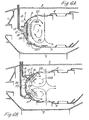
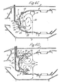
- Figures 6A to 6D show different configurations of the injectors 11 according to the invention in an annular combustion chamber using single rows of devices 11 ( Figures 6A and 6C) and double rows of devices 11 ( Figures 6B and 6D).
- the apertures 22, 23 are arranged to produce a single toroidal vortex 26 ( Figures 6A and 6C) and double toroidal vortices 26A ( Figures 6B and 6D), respectively.
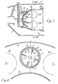
- Figures 7 and 8 show a combustor having an annular array of individual combustion tubes 30 each having a number of injectors 11 arranged In a manner analogous to that shown in Figures 1 to 6 and having a vortex 26 centred on the axis of the tube 30, Figure 7.
Landscapes
- Engineering & Computer Science (AREA)
- Chemical & Material Sciences (AREA)
- Combustion & Propulsion (AREA)
- Mechanical Engineering (AREA)
- General Engineering & Computer Science (AREA)
Description
- This invention relates to combustion apparatus for gas turbine engines.
- It is known in such apparatus to provide a combustion chamber arranged in an air jacket and having an upstream end wall provided with first and second inlet passages for air. Fuel is injected into the first passages to produce a primary fuel-air mixture therein. As the mixture leaves the first passages inside the chamber it mixes with air entering the chamber through the second passages. The resulting secondary mixture is caused to circulate in the upstream end portion of the chamber to further improve mixing before entering the main part of the chamber. During said circulation the mixture comes into contact with and is ignited by flame existing in said main part. It may occur in certain circumstances of operation, especially during idling, that the flame extends upstream into contact with said wall. Since the secondary mixture is still relatively fuel-rich (in the main part further air is added to result in leaner mixture) its consequent high burning temperature may cause destructive overheating of said end wall of the chamber. The same applies to any walls defining said passages insofar as the latter walls face the interior of the chamber.
- It has been suggested in our DE-A-2821680 to position the first passages, which necessarily must have some length to allow establishment of the primary mixture, so that their walls lie predominantly parallel to the adjacent portion of the chamber wall. This reduces the extent of projection of the passage walls into the chamber and therefore reduces the possibility of contact with the flame. The second passages were interdigitated with the first passages to cool any passage walls still exposed to the possibility of overheating. In this arrangement the outlets from both the first and the second passages necessarily had the same direction of flow.' As a result it was difficult to produce good mixing of the flows from the first and second passages. Also the design was relatively inflexible as regards promoting satisfactory said circulation. It is an object of this invention to reduce or overcome these difficulties.
- According to this invention there is provided combustion apparatus for gas turbine engines, comprising a combustion chamber having an end wall, first passages provided in said wall for introducing a primary fuel-air mixture into the chamber, second passages provided in said wall for introducing unfuelled air into the chamber, the first passages each having an outlet positioned to direct flow into the chamber in a direction predominantly parallel to the adjacent portion of said wall, characterized in that a said second passage is situated in proximity with each said outlet and in a position to direct air flow across the flow of primary mixture from the outlet so that the flows from adjacent said first and second passages combine to produce a flow of secondary mixture whose direction has a component away from said end wall of the chamber.
- By virtue of said component direction the secondary mixture passes clear of said chamber wall and is not, or is less likely to, ignite at the latter wall with destructive effects thereon. Simultaneously, the interaction between the mutually transverse flows from the first and second passages produces good mixing of these flows with consequential benefit for combustion efficiency. Further, there is generally no limitation as regards the direction of the outlets relative to the axis of the axisymmetric arrangement of the apparatus.
- Insofar as the flow from the second passages is no longer available to cool the walls of the passages, means are provided for passing a cooling film of air along the wall of the chamber and over the walls of the first passages. The secondary mixture, being directed away from the chamber wall, must necessarily penetrate the cooling film but it has been found that this penetration is essentially local and does not result in undue disruption of that film.
- Examples of this invention will now be described with reference to the accompanying drawings wherein:-
- Figure 1 is a sectional elevation of an annular combustor of a gas turbine engine,
- Figure 2 is a section on the line II-II in Figure 1 and shows a part of the annulus defined by the combustor,
- Figure 3 is a section on the line III-III in Figure 2,
- Figure 4 is a cross section on the line IV-IV in Figure 3,
- Figure 5 is a cross section similar to Figure 1 but showing a modification,
- Figures 6A-D are views similar to Figure 1 but showing further modifications,
- Figures 7 and 8 are views similar to Figures 1 and 2, and illustrate the application of the invention to a combustor having an annular array of individual combustion tubes.
- In the drawings the same reference numerals are used throughout to indicate the same or corresponding component parts of the different illustrated embodiments.
- Figures 1 and 2 show part of an annular combustor of a gas turbine engine which receives compressed air through a diffuser duct 1 from a compressor (not shown). The combustor has an
air jacket walls annular pilot zones 7, 8 separated by an annular centre body 6. - Each of the
annular pilot zones 7, 8 receives fuel-air mixture from a number of mixture injectors arranged in spaced apart relationship around an annulus defined by half-toroidalupstream end walls 9, 10 of therespective zones 7, 8. Each injector is indicated generally byreference numeral 11 in Figures 1 and 2 and has the construction shown, on an enlarged scale, in Figures 3 and 4. - Each
injector 11 has a primaryair inlet aperture 12 in theupstream end wall 9, 10 of the associatedzone 7, 8 for the admission of compressed air direct from the diffuser duct 1 through an associatedair inlet tube 13 which projects a short distance in an upstream direction from the outside of the associatedend wall 9, 10. In the twin pilot zone arrangement shown in Figures 1 and 2 theair inlet tubes 13 are provided withscarfed air intakes 14 which face in the direction of the compressed air flow from the diffuser duct 1. - A
fuel injection pipe 15 extends coaxially into theair inlet tube 13 and terminates adjacent the intake end of theinlet tube 13, as shown in Figures 3 and 4, for the purpose of directing liquid, gaseous or solid pulverulent fuel axially through the centre of theaperture 12. Thepipes 15 may communicate with any convenient arrangement of fuel supply lines and manifolds (not shown). - The generating curve of the half-
toroidal wall 9, 10 is concave to the interior of the chamber. At each injector 11 aflat wall 16 is secured chordally across thewall 9, 10 and defines therewith afirst passage 17 with which theaperture 12 communicates. Thewall 16 faces theaperture 12. Thepassage 17 has an outlet in the form of aslot 19 having a flow direction along thewall 9, 10 which is tangential in respect of the annulus of thewall 9, 10 and which is directed toward the nextadjacent injector 11. Theslot 19 is elongate in a direction substantially parallel to the internal surface of the combustionchamber end wall 9, 10 so that fuel and air, after impinging upon the internal surface of thewall 16 within thepassage 17, passes into the associatedpilot zone 7, 8 through theslot 19 in the form of a fan-shaped jet of fuel-air mixture referred to as the "primary mixture". - Adjacent each
slot 19 thewall 9, 10 is provided with a second inlet passage 21 having an outlet in the form of aslot 20 which is elongate in a direction substantially parallel to the direction of elongation of theassociated slot 19. A jet of secondary air therefore enters thepilot zone 7, 8 from the diffuser duct 1 through theslot 20 so as to deflect the jet of primary mixture obliquely away from theupstream wall 9, 10 as shown diagrammatically in Figures 3 and 4. The passage 21 may define a scoop or shroud, Figure 1, to ensure that theslot 20 is fed by total head pressure of the compressor air rather than the static pressure of the air flowing externally over the upstream end of the combustion chamber. - The
walls air inlet apertures toroidal vortices 26 about the axis of the combustion chamber. Theapertures 22 are shrouded to direct the entering air in the form of acooling film 24 along thewall 9, 10 and over the surfaces of thewalls 16 facing the interior of the combustion chamber, thefilm 24 constituting a peripheral layer of thevortex 26 passing radially in respect of the annulus axis of thewalls 9, 10. - In operation of the
injectors 11 the impingement of the fuel and air on the internal surfaces of thewall 16 causes some atomisation of the fuel and mixture of the fuel and air in thepassage 17, before expulsion of the primary mixture into the associatedpilot zone 7, 8 through theslots 19. The jet of air entering the combustion chamber through any oneslot 20 and perpendicular to thewalls 9, 10 intersects and mixes with the efflux from theadjacent slot 19, resulting a thick fan-shaped flow being ajet 19A of well-atomized air-fuel mixture referred to as the "secondary mixture". Due to the interaction of the primary mixture emerging from theslot 19 and the secondary air emerging from theslot 20, the secondary mixture has, as mentioned, a direction obliquely away from thewalls 9, 10. In the present example the direction of thejet 19A has a component X circumferentially along theannular walls 9, 10 and a component Y in the direction of the axis of the annulus of thewalls 9, 10. Both said components are transverse to the direction of thefilm 24. The resultant direction of thejet 19A is such that this jet penetrates thefilm 24 but since neither said component is opposed to the direction of thefilm 24 the penetration by thejet 19A does not significantly disrupt thefilm 24. This is particularly illustrated in Figure 4 where it will be seen that thefilm 24 is free to enter between thejet 19A and thewalls 9, 10 as shown at 24A, to avoid damage to those walls due to any premature ignition of the air-fuel mixture. - An alternative arrangement of
injectors 11, in the same twin pilot zone arrangement as shown in Figures 1, 2, is shown diagrammatically in Figure 5 where theoutlet slots 19 of theinjectors 11 face radially along thewalls 9, 10, i.e. face in a direction which is radial in respect of the annulus axis or which has at least a component which is radial in respect of that axis. In such a case theslots 19 must face in the same sense of direction as that of the flow of thefilm 24. The slots -20 produce, as before, a flow perpendicular to thewalls 9, 10 so that the jet of secondary mixture, in this case denoted 19B, has a resultant direction away from thewalls 9, 10 and obliquely penetrates thefilm 24 where the latter sweeps over thewall 16 of therespective passage 17. This means that thefilm 24 is locally absorbed by thejet 19B and, to reestablish thefilm inlets 25 are provided adjacent theslots 20 to feed air along thewalls 9, 10 in the direction of thefilm 24. Theinlets 25 also serve as shrouds for directing air toward theslots 20 as shown. - Figures 6A to 6D show different configurations of the
injectors 11 according to the invention in an annular combustion chamber using single rows of devices 11 (Figures 6A and 6C) and double rows of devices 11 (Figures 6B and 6D). Correspondingly theapertures toroidal vortices 26A (Figures 6B and 6D), respectively. - Figures 7 and 8 show a combustor having an annular array of
individual combustion tubes 30 each having a number ofinjectors 11 arranged In a manner analogous to that shown in Figures 1 to 6 and having avortex 26 centred on the axis of thetube 30, Figure 7.
Claims (10)
Applications Claiming Priority (2)
| Application Number | Priority Date | Filing Date | Title |
|---|---|---|---|
| GB7917335 | 1979-05-18 | ||
| GB7917335 | 1979-05-18 |
Publications (2)
| Publication Number | Publication Date |
|---|---|
| EP0019417A1 EP0019417A1 (en) | 1980-11-26 |
| EP0019417B1 true EP0019417B1 (en) | 1983-01-12 |
Family
ID=10505244
Family Applications (1)
| Application Number | Title | Priority Date | Filing Date |
|---|---|---|---|
| EP80301498A Expired EP0019417B1 (en) | 1979-05-18 | 1980-05-08 | Combustion apparatus for gas turbine engines |
Country Status (4)
| Country | Link |
|---|---|
| US (1) | US4365477A (en) |
| EP (1) | EP0019417B1 (en) |
| JP (1) | JPS5914693B2 (en) |
| DE (1) | DE3061595D1 (en) |
Cited By (1)
| Publication number | Priority date | Publication date | Assignee | Title |
|---|---|---|---|---|
| RU201848U1 (en) * | 2020-08-12 | 2021-01-15 | федеральное государственное бюджетное образовательное учреждение высшего образования "Ульяновский государственный технический университет" | COMBUSTION CHAMBER OF A GAS TURBINE ENGINE WITH AN ACTIVE COOLING ZONE |
Families Citing this family (19)
| Publication number | Priority date | Publication date | Assignee | Title |
|---|---|---|---|---|
| US4928479A (en) * | 1987-12-28 | 1990-05-29 | Sundstrand Corporation | Annular combustor with tangential cooling air injection |
| US5088287A (en) * | 1989-07-13 | 1992-02-18 | Sundstrand Corporation | Combustor for a turbine |
| US5197289A (en) * | 1990-11-26 | 1993-03-30 | General Electric Company | Double dome combustor |
| US5195315A (en) * | 1991-01-14 | 1993-03-23 | United Technologies Corporation | Double dome combustor with counter rotating toroidal vortices and dual radial fuel injection |
| US5165226A (en) * | 1991-08-09 | 1992-11-24 | Pratt & Whitney Canada, Inc. | Single vortex combustor arrangement |
| US5154060A (en) * | 1991-08-12 | 1992-10-13 | General Electric Company | Stiffened double dome combustor |
| DE69306025T2 (en) * | 1992-03-30 | 1997-05-28 | Gen Electric | Construction of a combustion chamber dome |
| US6089025A (en) * | 1998-08-24 | 2000-07-18 | General Electric Company | Combustor baffle |
| US6286317B1 (en) * | 1998-12-18 | 2001-09-11 | General Electric Company | Cooling nugget for a liner of a gas turbine engine combustor having trapped vortex cavity |
| US6711900B1 (en) * | 2003-02-04 | 2004-03-30 | Pratt & Whitney Canada Corp. | Combustor liner V-band design |
| FR2866079B1 (en) * | 2004-02-05 | 2006-03-17 | Snecma Moteurs | DIFFUSER FOR TURBOREACTOR |
| US7421843B2 (en) * | 2005-01-15 | 2008-09-09 | Siemens Power Generation, Inc. | Catalytic combustor having fuel flow control responsive to measured combustion parameters |
| DE102006051286A1 (en) * | 2006-10-26 | 2008-04-30 | Deutsches Zentrum für Luft- und Raumfahrt e.V. | Combustion device, has combustion chamber with combustion space and air injecting device including multiple nozzles arranged on circular line, where nozzles have openings formed as slotted holes in combustion space |
| US7794201B2 (en) * | 2006-12-22 | 2010-09-14 | General Electric Company | Gas turbine engines including lean stator vanes and methods of assembling the same |
| US20100192578A1 (en) * | 2009-01-30 | 2010-08-05 | General Electric Company | System and method for suppressing combustion instability in a turbomachine |
| FR2944584B1 (en) * | 2009-04-17 | 2014-08-22 | Turbomeca | COMBUSTION CHAMBER WITH CHIMNEY BOTTOM REFRIGERATOR BRASE. |
| US8381526B2 (en) * | 2010-02-15 | 2013-02-26 | General Electric Company | Systems and methods of providing high pressure air to a head end of a combustor |
| EP3436752B1 (en) | 2016-03-30 | 2021-06-30 | Marine Canada Acquisition Inc. | Vehicle heater and controls therefor |
| US20260043544A1 (en) * | 2024-08-06 | 2026-02-12 | General Electric Company | Combustor having driver jets for a gas turbine engine |
Family Cites Families (7)
| Publication number | Priority date | Publication date | Assignee | Title |
|---|---|---|---|---|
| DE1039785B (en) * | 1957-10-12 | 1958-09-25 | Maschf Augsburg Nuernberg Ag | Combustion chamber with high heat load, especially for the combustion of low calorific value, gaseous fuels in gas turbine systems |
| US3808803A (en) * | 1973-03-15 | 1974-05-07 | Us Navy | Anticarbon device for the scroll fuel carburetor |
| GB1429677A (en) * | 1973-03-20 | 1976-03-24 | Rolls Royce | Gas turbine engine combustion equipment |
| US3937008A (en) * | 1974-12-18 | 1976-02-10 | United Technologies Corporation | Low emission combustion chamber |
| FR2312654A1 (en) * | 1975-05-28 | 1976-12-24 | Snecma | COMBUSTION CHAMBERS IMPROVEMENTS FOR GAS TURBINE ENGINES |
| US4018043A (en) * | 1975-09-19 | 1977-04-19 | Avco Corporation | Gas turbine engines with toroidal combustors |
| GB1600130A (en) * | 1977-05-21 | 1981-10-14 | Rolls Royce | Combustion systems |
-
1980
- 1980-05-08 DE DE8080301498T patent/DE3061595D1/en not_active Expired
- 1980-05-08 EP EP80301498A patent/EP0019417B1/en not_active Expired
- 1980-05-16 US US06/150,366 patent/US4365477A/en not_active Expired - Lifetime
- 1980-05-19 JP JP55065463A patent/JPS5914693B2/en not_active Expired
Cited By (1)
| Publication number | Priority date | Publication date | Assignee | Title |
|---|---|---|---|---|
| RU201848U1 (en) * | 2020-08-12 | 2021-01-15 | федеральное государственное бюджетное образовательное учреждение высшего образования "Ульяновский государственный технический университет" | COMBUSTION CHAMBER OF A GAS TURBINE ENGINE WITH AN ACTIVE COOLING ZONE |
Also Published As
| Publication number | Publication date |
|---|---|
| JPS5914693B2 (en) | 1984-04-05 |
| EP0019417A1 (en) | 1980-11-26 |
| US4365477A (en) | 1982-12-28 |
| JPS55155118A (en) | 1980-12-03 |
| DE3061595D1 (en) | 1983-02-17 |
Similar Documents
| Publication | Publication Date | Title |
|---|---|---|
| US4365477A (en) | Combustion apparatus for gas turbine engines | |
| US4374466A (en) | Gas turbine engine | |
| US11549429B2 (en) | Engine mixing structures | |
| US7908863B2 (en) | Fuel nozzle for a gas turbine engine and method for fabricating the same | |
| US4327547A (en) | Fuel injectors | |
| JP5468812B2 (en) | Combustor assembly and fuel nozzle for gas turbine engine | |
| JP3782822B2 (en) | Fuel injection device and method of operating the fuel injection device | |
| JP2928125B2 (en) | Method of operating a gas turbine device and method of reducing combustion instability in a low NOx gas turbine device | |
| US2856755A (en) | Combustion chamber with diverse combustion and diluent air paths | |
| US6845621B2 (en) | Annular combustor for use with an energy system | |
| EP1010946A2 (en) | Fuel injector bar for a gas turbine engine combustor | |
| US11008932B2 (en) | Engine mixing structures | |
| US10584638B2 (en) | Turbine nozzle cooling with panel fuel injector | |
| US5303554A (en) | Low NOx injector with central air swirling and angled fuel inlets | |
| JPH1089688A (en) | Highly uniform injection system | |
| JPH07180835A (en) | gas turbine | |
| US3952503A (en) | Gas turbine engine combustion equipment | |
| EP0587580A1 (en) | GAS TURBINE COMBUSTION CHAMBER. | |
| CN108731029A (en) | Jet fuel nozzle | |
| JPH10132278A (en) | gas turbine | |
| US3820324A (en) | Flame tubes for gas turbine engines | |
| US8448441B2 (en) | Fuel nozzle assembly for a gas turbine engine | |
| GB2035540A (en) | A gas turbine engine fuel injector | |
| JP3878980B2 (en) | Fuel injection device for combustion device | |
| US4249373A (en) | Gas turbine engine |
Legal Events
| Date | Code | Title | Description |
|---|---|---|---|
| PUAI | Public reference made under article 153(3) epc to a published international application that has entered the european phase |
Free format text: ORIGINAL CODE: 0009012 |
|
| AK | Designated contracting states |
Designated state(s): BE CH DE FR GB NL SE |
|
| 17P | Request for examination filed |
Effective date: 19810513 |
|
| GRAA | (expected) grant |
Free format text: ORIGINAL CODE: 0009210 |
|
| AK | Designated contracting states |
Designated state(s): BE CH DE FR GB LI NL SE |
|
| REF | Corresponds to: |
Ref document number: 3061595 Country of ref document: DE Date of ref document: 19830217 |
|
| PGFP | Annual fee paid to national office [announced via postgrant information from national office to epo] |
Ref country code: NL Payment date: 19830418 Year of fee payment: 4 Ref country code: CH Payment date: 19830418 Year of fee payment: 4 |
|
| PGFP | Annual fee paid to national office [announced via postgrant information from national office to epo] |
Ref country code: SE Payment date: 19830430 Year of fee payment: 4 |
|
| ET | Fr: translation filed | ||
| PGFP | Annual fee paid to national office [announced via postgrant information from national office to epo] |
Ref country code: BE Payment date: 19830630 Year of fee payment: 4 |
|
| PG25 | Lapsed in a contracting state [announced via postgrant information from national office to epo] |
Ref country code: SE Effective date: 19840509 |
|
| PG25 | Lapsed in a contracting state [announced via postgrant information from national office to epo] |
Ref country code: LI Effective date: 19840531 Ref country code: CH Effective date: 19840531 Ref country code: BE Effective date: 19840531 |
|
| BERE | Be: lapsed |
Owner name: ROLLS-ROYCE LTD Effective date: 19840508 |
|
| PG25 | Lapsed in a contracting state [announced via postgrant information from national office to epo] |
Ref country code: NL Effective date: 19841201 |
|
| NLV4 | Nl: lapsed or anulled due to non-payment of the annual fee | ||
| REG | Reference to a national code |
Ref country code: CH Ref legal event code: PL |
|
| PGFP | Annual fee paid to national office [announced via postgrant information from national office to epo] |
Ref country code: FR Payment date: 19900410 Year of fee payment: 11 |
|
| PGFP | Annual fee paid to national office [announced via postgrant information from national office to epo] |
Ref country code: DE Payment date: 19900427 Year of fee payment: 11 |
|
| PGFP | Annual fee paid to national office [announced via postgrant information from national office to epo] |
Ref country code: GB Payment date: 19910412 Year of fee payment: 12 |
|
| PG25 | Lapsed in a contracting state [announced via postgrant information from national office to epo] |
Ref country code: FR Effective date: 19920131 |
|
| PG25 | Lapsed in a contracting state [announced via postgrant information from national office to epo] |
Ref country code: DE Effective date: 19920303 |
|
| REG | Reference to a national code |
Ref country code: FR Ref legal event code: ST |
|
| PG25 | Lapsed in a contracting state [announced via postgrant information from national office to epo] |
Ref country code: GB Effective date: 19920508 |
|
| GBPC | Gb: european patent ceased through non-payment of renewal fee |
Effective date: 19920508 |
|
| EUG | Se: european patent has lapsed |
Ref document number: 80301498.4 Effective date: 19850417 |
|
| PLBE | No opposition filed within time limit |
Free format text: ORIGINAL CODE: 0009261 |
|
| STAA | Information on the status of an ep patent application or granted ep patent |
Free format text: STATUS: NO OPPOSITION FILED WITHIN TIME LIMIT |