EP0019263B2 - Microscope lens system - Google Patents
Microscope lens system Download PDFInfo
- Publication number
- EP0019263B2 EP0019263B2 EP80102638A EP80102638A EP0019263B2 EP 0019263 B2 EP0019263 B2 EP 0019263B2 EP 80102638 A EP80102638 A EP 80102638A EP 80102638 A EP80102638 A EP 80102638A EP 0019263 B2 EP0019263 B2 EP 0019263B2
- Authority
- EP
- European Patent Office
- Prior art keywords
- objectives
- lens
- dispersive
- tube lens
- adapters
- Prior art date
- Legal status (The legal status is an assumption and is not a legal conclusion. Google has not performed a legal analysis and makes no representation as to the accuracy of the status listed.)
- Expired
Links
Images


Classifications
-
- G—PHYSICS
- G02—OPTICS
- G02B—OPTICAL ELEMENTS, SYSTEMS OR APPARATUS
- G02B21/00—Microscopes
- G02B21/02—Objectives
Definitions
- the invention relates to a microscope optical system which makes it possible to make the objectives of different microscope systems interchangeable.
- the chromatic transverse deviation is not fully corrected for microscope objectives with finite focal lengths - which are referred to below as objectives of the first type.
- the degree of correction varies from manufacturer to manufacturer.
- the remaining chromatic cross deviation in the intermediate image is compensated for by special eyepieces.
- microscope lenses with infinite focal lengths have been developed. In these there is a parallel beam path behind the lens, so that the introduction of additional optics (beam splitter, filter, etc.) is easily possible.
- additional optics beam splitter, filter, etc.
- the intermediate image is generated by means of an additional lens system, the so-called tube lens system.
- Microscope objectives with infinite focal lengths are also known, which are corrected so that an aberration-free intermediate image is created in connection with the tube lens system.
- a reference to this can be found in the Yearbook for Optics and Precision Engineering 1978 ".
- DE-C-2 047 673 describes a likewise fixed correction element which, with a correction effect similar to that proposed in DE-B-1 472 082, shifts the initial focal length of the interchangeable lenses to infinity.
- a positive single lens which is also provided in the tube, corrects the chromatic aberration of the lenses and creates an aberration-free intermediate image. This correction element also changes the imaging scale of the interchangeable lenses.
- a device is known from the company publication "Microprojector with Xenon Burner” from Ernst Leitz Wetzlar GmbH, on whose lens slider not only lenses with an infinite focal length, but also a lens with a finite focal length can be used.
- an achromatic negative putty is used, which extends the focal length of the finite lens to infinity.
- both types of lens are here in terms of chromatic Aberrations corrected in the same way.
- microscope objectives of the first and second types make it possible to use microscope objectives with finite focal lengths and chromatic transverse effects in the intermediate image on microscopes designed for objectives with infinite focal lengths and color-free intermediate images; at the same time, these microscope objectives with an infinite focal length should be able to be used in microscopes designed for objectives with a finite focal length.
- the correction state of the microscope objectives of the first and second type with regard to the chromatic magnification difference in the intermediate image is therefore different when using the new optical system.
- dispersive adapters with negative refractive power for attachment to the lenses with finite focal lengths for operation in connection with the dispersive tube lens and dispersive adapters with positive refractive power for attachment to the lenses with infinite focal lengths are provided,
- the dispersions and the refractive powers of the adapters with positive refractive powers are mutually the same and correspond to the corresponding values for the dispersive tube lens and the dispersions and the refractive powers of the adapters with negative refractive powers are identical to one another and, in terms of amount, correspond to the corresponding value for the dispersive tube lens and essentially the condition when dimensioning the tube lens and the adapter is observed, whereby v d - the Abbe number of the glasses used in the lenses or cemented component, f - the focal length of the respective lenses or cemented component, L - the distance of its main plane from the exit pupil of the lenses used in connection with the tube lens and CHV - is the cross-color error to be compensated for these lenses.
- the task is solved by that to achieve mutual compatibility of the two lens types, the negative link of the telanlin system is removed from the tube and is designed in the form of an achromatic adapter for attachment to the lens with a finite back focal length, the chromatic correction state of the lenses with an infinite focal length is chosen so that the color-free intermediate image can be generated by a dispersive tube lens that is undercorrected with respect to the CHL, dispersive adapter with negative refractive power for attachment to the lenses with finite focal length for operation in conjunction with the dispersive tube lens and dispersive adapter with refractive power 0 (afocal adapter) for attachment to the lenses with infinite focal length for operation in conjunction with the positive achromatic member the Telanlinensystem are provided, the dispersion of the
- v d the Abbe number of the glasses used for the lenses or cemented component
- f - the focal length of the respective lenses or cemented component
- L - the distance of its main plane from the exit pupil of the lenses used in connection with the tube lens
- CHV - is the cross-color error to be compensated for these lenses.
- the manufacturer has the advantage of not having to manufacture and keep the lenses of both types when changing the system in the transition phase, since the lens series of one type are always compatible with the lens series of the second type by combination with the appropriate adapter .
- the manufacturer can supply the user of the first type of lens series of the second type together with the corresponding adapters, which also can already be built into the lens housing.
- the user can easily make the transition to the lens system of the second type while maintaining his interchangeable lenses of the first type, since these need only be equipped with the adapters provided for this.
- the adapters can be framed so that an easily replaceable attachment to the lens housing is made possible. In this case, the user himself is able to provide the lenses that he wants to make available for other use with the necessary adapter.
- the adapters and the tube lens of the new system are the same with regard to the amount of refractive power and their dispersion, on the one hand it is achieved that the imaging scale of lenses of the first type does not change when used on new tubes.
- the chromatic aberrations in the intermediate image depend quite simply on the system parameters, which can then be easily optimized with regard to a color-free intermediate image.
- the tube lenses of the devices of the second type with their main planes at a distance from the object plane that corresponds to 0.5 to 1.3 times their focal length.
- the influence of the position of the tube lens on the transverse color error in the intermediate image can easily be compensated for in this area on the basis of the currently customary values for the color magnification error of lenses of the first type with the aid of the dispersion of the adapter or the tube lens. It is then possible by suitable selection of available types of glass with regard to their dispersion to design the tube lens and the adapter as individual lenses, avoiding cemented elements, in order to achieve the mutual chromatic correction of the intermediate image.
- the dispersive afocal adapter is integrated into the tube, then in connection with the remaining positive achromatic tube lens, it is possible to easily generate a color-free intermediate image.
- the dependency of the transverse color error in the intermediate image on the position of the dispersive link furthermore offers the possibility of individually realizing the desire for complete elimination of the transverse color error for all lenses.
- the displacement of the adjustment element also has no influence on the monochromatic aberrations and the chromatic longitudinal errors.
- lenses of the first type can also be easily adapted to the tube with the remaining achromatic tube lens system, the chromatic correction of which was carried out without taking into account the afocal correction element.
- FIGS. 10-16 show examples of the normalized course of the chromatic longitudinal deviation as a function of the wavelength for the lenses, adapters and tube lenses in the arrangement according to FIGS. 1-9.
- a lens 1 of finite focal length from the object produces an intermediate image 7 with a color transverse error in the finite area and thus corresponds to a system of the first type.
- 9 denotes the mechanical limitation of the lens housing.
- a tube lens system 20 with an undercorrected chromatic longitudinal deviation produces the color-free intermediate image 8 without influencing the monochromatic image errors which have already been corrected in the objective 2.
- the refractive power of the tube lens system 20 is selected so that an adapter 4 with the amount of the same but negative refractive power and the same dispersion can replace the objective 2 in FIG. 2 with a conventional objective 1 to whose housing it is attached (FIG. 4 ).
- an adapter 4 which moves the focal length of conventional lenses 1 to infinity, they can be used on microscope tubes of the second type without changing their imaging scale.
- the intermediate image is colorless.
- an objective 2 with an infinite focal length is provided with an adapter 3 which corresponds to the adapter 7 (FIG. 4) except for the sign of the refractive power and thus has the same refractive power as the tube lens system 20, then With this combination, a lens of finite output focal length can also be replaced without changing the imaging scale.
- the intermediate image 7 has the same transverse color error as that in FIG. 1, which, in contrast to the longitudinal color error, depends on the position of the adapter 3 (distance from the objective pupil).
- the number of free parameters is manageable. Since it is assumed that both lens classes U and E are corrected for the monochromatic image errors and that the focal length of the adapters 3 and 4 and the tube lens system 20 is in the decimeter range in accordance with the common values for optical tube lengths used, it is possible to consider the lens shapes ( Radii), which have no influence on the chromatic aberrations, are omitted in the adapters or in the tube optics. Rather, the radii can be chosen so that the main planes of the adapters in the various lenses always take the position that is required to achieve the desired chromatic correction, without bringing the adapters themselves into these positions.
- v d the Abbe number of the glasses used for the lenses or cemented component
- f the focal length of the respective lenses or cemented component
- L - the distance of their main planes from the exit pupil of the lenses used in connection with the tube lens system
- CHV - is the cross-color error to be compensated for these lenses.
- FIG. 10 shows the normalized course of the chromatic longitudinal deviation (CHL) for an objective E of the first kind (achromatic with 10x magnification, aperture 0.22, initial focal length 160 mm), the intermediate image of which has a color magnification error (CHV) of 1.4%.
- the adapter and the tube lens are e.g. B. dimensioned as putty so that the desired dispersive behavior results.
- FIG. 14 describes the chromatic correction of the system shown in FIG. 4.
- the color transverse error (CHV) in the intermediate image according to FIG. 14c becomes zero, since the small contribution of the adapter 4, which is attached in the vicinity of the objective pupil, to the CHV compared with the positive adapter 3 in FIG CHV of both lens types E and U is compensated.
- CHV color transverse error
- the values for the CHV in FIGS. 11-14 can all be calculated from equation 1 if it is taken into account that the adapters 3 and 4 are approximately 10 mm away from the objective pupil.
- FIGS. 5-7 outline the achievement of mutual compatibility of the systems described above with the aid of an achromatic negative adapter 14 and a further afocal adapter 5, it being assumed that the system of the first type contains a so-called telan system which Adjust the image distance to the tripod dimensions using a positive (10) and negative (11) achromatic link. Since the use of lenses E on new tubes of the second type has already been outlined with the aid of the negative adapter 4 in FIG. 4, only the interchangeability of the two lens types E and U on tubes of the system of the first type is shown.
- a lens of the second type can be combined using an afocal adapter 5 (FIG. 7), which has the same dispersive behavior as the adapter 3 in FIG. 3.
- an intermediate image 7 with transverse color errors is obtained again.
- FIGS. 8 and 9 A further sensible possibility of adapting the objectives E and U to such a tube is shown in FIGS. 8 and 9.
- the afocal member 15 with the dispersive properties of the adapter 5 is arranged in the tube in the vicinity of the achromatic member 10.
- This system has the same structure in terms of its optical effect as that outlined in FIGS. 2 and 4 and differs only in that refractive power and dispersion of the tube lens 20 in FIGS. 2 and 4 are applied by the separate members 10 and 15.
- the transverse color error in the intermediate image 8 can be completely compensated for in a simple manner, as a result of which small differences in the correction state of different lenses or manufacturing tolerances can be compensated for without adjusting the plane of focus.
- adjustment elements are provided on the tube, with which the said longitudinal displacement of the link 15 can be carried out reproducibly and continuously.
- the use of such an element is not only possible in connection with the optical system outlined above. Even without providing an adapter with which lenses of the first and second type are made compatible (e.g. for incompatible special microscopes), the use of adjustment elements for the complete elimination of the color cross-error in the intermediate image is conceivable and sensible.
- FIG. 16a again shows the course of the CHL of the objective E as in FIG. 10.
- the achromatic tube optics 11, 10 or the adapter 14 sketched in FIGS. 5 and 6 remain almost without influence on the transverse color error (FIG. 16b), so that for both cases the course of the CHL shown in FIG. 16c results, which essentially corresponds to FIG. 16a.
- FIG. 15 shows the compensation of the color errors of the lens U according to an arrangement according to FIG. 7 by the adapter 5 (FIG. 15b), the adapter 3 in FIG. 3 with the same position and with the same dispersive behavior (see FIG. 12b ) gives the result shown in FIG. 15c with a transverse color error of 1.4%.
Abstract
Description
Bei der Erfindung handelt es sich um ein Mikroskopoptiksystem das gestattet, die Objektive verschiedener Mikroskopsysteme untereinander austauschbar zu machen.The invention relates to a microscope optical system which makes it possible to make the objectives of different microscope systems interchangeable.
Die bekannten zur Zeit auf dem Markt befindlichen Mikroskope arbeiten nach verschiedenen, nicht kompatiblen Systemen, die sich
- a) in der Ausgangsschnittweite der verwendeten Wechselobjektive und
- b) im Korrektionszustand der Wechselobjektive unterscheiden.
- a) in the initial focal length of the interchangeable lenses used and
- b) differentiate in the corrective state of the interchangeable lenses.
Es ist bisher weitgehend üblich, in Mikroskopen Objektive mit endlicher Schnittweite zu verwenden. Diese Objektive erzeugen direkt ein Zwischenbild des Objektes, das mittels des Okulars beobachtet wird. Objektiv und Okular haben einen, durch die Lage des Zwischenbildes festgelegten definierten Abstand, d. h. bei Mikroskopen mit Objektiven endlicher Schnittweite ist die mechanische Tubuslänge eine bestimmte Größe.It has so far been largely customary to use lenses with finite focal lengths in microscopes. These lenses directly generate an intermediate image of the object, which is observed using the eyepiece. The lens and eyepiece have a defined distance defined by the position of the intermediate image, i. H. in microscopes with objectives of finite focal length, the mechanical tube length is a certain size.
Im allgemeinen wird bei Mikroskop-Objektiven mit endlicher Schnittweite - welche im folgenden als Objektive erster Art bezeichnet werden - die chromatische Querabweichung nicht voll auskorrigiert. Der Grad der Korrektur ist von Hersteller zu Hersteller verschieden. Die noch vorhandene chromatische Querabweichung im Zwischenbild wird durch spezielle Okulare kompensiert.In general, the chromatic transverse deviation is not fully corrected for microscope objectives with finite focal lengths - which are referred to below as objectives of the first type. The degree of correction varies from manufacturer to manufacturer. The remaining chromatic cross deviation in the intermediate image is compensated for by special eyepieces.
In den letzten Jahren sind Mikroskop-Objektive mit unendlicher Schnittweite entwickelt worden. Bei diesen besteht hinter dem Objektiv paralleler Strahlengang, so daß das Einbringen von Zusatzoptik (Strahlenteiler, Filter, etc.) leicht möglich ist. Das Zwischenbiid wird bei Mikroskopobjektiven mit unendlicher Schnittweite - welche im folgenden als Objektive zweiter Art bezeichnet werden - mittels eines zusätzlichen Linsensystems, des sogenannten Tubuslinsensystems erzeugt.In recent years, microscope lenses with infinite focal lengths have been developed. In these there is a parallel beam path behind the lens, so that the introduction of additional optics (beam splitter, filter, etc.) is easily possible. In the case of microscope objectives with an infinite focal length - which are referred to below as objectives of the second type - the intermediate image is generated by means of an additional lens system, the so-called tube lens system.
Es ist klar, daß bei Mikroskop-Objektiven der zweiten Art die mechanische Tubuslänge keine definierte Größe ist: sie kann je nach Anforderung verschieden groß sein.It is clear that with microscope objectives of the second type the mechanical tube length is not a defined size: it can be of different sizes depending on the requirements.
Es sind auch Mikroskop-Objektive mit unendlicher Schnittweite bekannt, die so auskorrigiert sind, daß in Verbindung mit dem Tubuslinsensystem ein aberrationsfreies Zwischenbild entsteht. Ein Hinweis darauf findet sich im Jahrbuch für Optik und Feinmechanik 1978". Hierbei handelt es sich aber um spezielle Objektive mit monochromatischen Bildfehler, die ebenfalls durch daß Tubuslinsensystem behoben werden müssen.Microscope objectives with infinite focal lengths are also known, which are corrected so that an aberration-free intermediate image is created in connection with the tube lens system. A reference to this can be found in the Yearbook for Optics and Precision Engineering 1978 ". However, these are special lenses with monochromatic image defects, which must also be remedied by the tube lens system.
Wenn nun ein Hersteller von Mikroskopen mit Objektiven der ersten auf solche mit Objektiven der zweiten Art übergehen möchte, so wäre das für ihn sehr teuer, da er für eine recht lange Übergangszeit den Bedürfnissen der Benutzer nach Ausbaumöglichkeit ihrer alten Geräte dadurch Rechnung tragen müßte, daß der Komponenten beider Systeme anbietet. Selbst dann taucht jedoch für einen Benutzer das Problem auf; daß er beim Übergang auf Mikroskope mit Objektiven der zweiten Art seine bisherigen Wechselobjektive mangels Kompatibilität nicht einsetzen kann.If a manufacturer of microscopes with lenses of the first type now wanted to switch to lenses with the second type, this would be very expensive for him, since he would have to take into account the needs of the users for expanding their old devices for a rather long transition period in that which offers components of both systems. Even then, the problem arises for a user; that he cannot use his previous interchangeable lenses due to the lack of compatibility when changing to microscopes with lenses of the second type.
Es ist aus der US-A-3 132 200 bekannt nicht auskorrigierte Mikroskop-Objektive, die unendliche Ausgangsschnittweite besitzen, mit einem Korrekturglied zu kombinieren, das fest im Tubus eingebaut ist und ein aberrationsfreies Zwischenbild erzeugt. Das Korrekturglied besitzt jedoch insbesondere wegen seiner monochromatischen Aberration nur für ein Wechselobjektiv der bestimmten Objektivserie optimale Korrekturwirkung. Das Einführen einer positiven Koma durch das Korrekturglied bedingt einen positiven Astigmatismus an dieser Stelle. Beide Fehler wirken sich bei Pupillenverschiebungen, wie sie bei Fokussierbewegungen zwischen Objektiv und Tubuslinse und beim Einbringen von Strahlteilern oder Filtern auftreten, besonders nachteilig aus.It is known from US-A-3 132 200 to combine uncorrected microscope objectives, which have an infinite output focal length, with a correction element which is permanently installed in the tube and produces an aberration-free intermediate image. However, due to its monochromatic aberration, the correction element has an optimal correction effect only for an interchangeable lens of the specific lens series. The introduction of a positive coma by the correction member requires a positive astigmatism at this point. Both errors have a particularly disadvantageous effect on pupil displacements, such as occur during focusing movements between the objective and tube lens and when inserting beam splitters or filters.
Aus der DB-B-1 472 082 ist bekannt, ein die Schnittweite von Wechselobjektiven vergrößerndes feststehendes Korrekturglied in Form eines negativen Kittgliedes zu verwenden, das Bildfeldkrümmung und Astigmatismus kompensiert. Seine 5-fache vergrößernde Wirkung ist auf die Anpassung einer speziellen, niedrig vergrößernden Objektivserie zugeschnitten.From DB-B-1 472 082 it is known to use a fixed correction element in the form of a negative cementing element which increases the focal length of interchangeable lenses and which compensates for image curvature and astigmatism. Its 5-fold magnifying effect is tailored to the adaptation of a special, low-magnification lens series.
In der DE-C-2 047 673 ist ein ebenfalls feststehendes Korrekturglied beschrieben, das bei ähnlich korrigierender Wirkung wie das in der DE-B-1 472 082 vorgeschlagene die Ausgangsschnittweite der Wechselobjektive nach unendlich verlegt. Eine ebenfalls vorgesehene im Tubus feststehende, positive Einzellinse korrigiert den Farbquerfehler der Objektive und erzeugt ein aberrationsfreies Zwischenbild. Auch dieses Korrekturglied verändert den Abbildungsmaßstab der Wechselobjektive.DE-C-2 047 673 describes a likewise fixed correction element which, with a correction effect similar to that proposed in DE-B-1 472 082, shifts the initial focal length of the interchangeable lenses to infinity. A positive single lens, which is also provided in the tube, corrects the chromatic aberration of the lenses and creates an aberration-free intermediate image. This correction element also changes the imaging scale of the interchangeable lenses.
Bei allen diesen bekannten Korrektursystemen ist das Korrekturglied fest in den Tubus integriert und, legt damit die Art der zu verwendenden Objektivserien fest. Ein Umrüsten des Systems durch Einbau anderer Korrekturglieder ist zeitraubend und aufwendig und damit teuer. Diese Korrektursysteme ermöglichen Kompatibilität verschiedener Systeme also nur in dem Sinne, daß neue Objektivserien durch einmalige Umrüstung älterer Tuben verwendet werden können.In all of these known correction systems, the correction element is firmly integrated in the tube and thus defines the type of lens series to be used. Retrofitting the system by installing other correction elements is time-consuming and complex and therefore expensive. These correction systems enable compatibility of different systems only in the sense that new lens series can be used by retrofitting older tubes.
Aus der Firmenschrift "Mikroprojektor mit Xenon-Brenner" der Ernst Leitz Wetzlar GmbH ist ein Gerät bekannt, an dessen Objektivschieber neben Objektive mit unendlicher Schnittweite auch ein Objektiv mit endlicher Schnittweite verwendet werden kann. Hierzu ist ein achromatisches negatives Kittglied verwendet, das die Schnittweite des Endlich-Objektivs nach unendlich verlegt. Beide Objektivarten sind hier jedoch in Bezug auf die chromatische Aberrationen in gleicher Weise korrigiert.A device is known from the company publication "Microprojector with Xenon Burner" from Ernst Leitz Wetzlar GmbH, on whose lens slider not only lenses with an infinite focal length, but also a lens with a finite focal length can be used. For this purpose, an achromatic negative putty is used, which extends the focal length of the finite lens to infinity. However, both types of lens are here in terms of chromatic Aberrations corrected in the same way.
Es ist nun die Aufgabe der vorliegenden Erfindung, ein Optiksystem für Mikroskope zu schaffen, welches Mikroskop-Objekive der ersten und zweiten Art voll kompatibel macht. Damit soll es möglich werden, Mikroskop-Objektive mit endlicher Schnittweite und chromatischer Querabwirkung im Zwischenbild an Mikroskopen zu verwenden, die für Objektive mit unendlicher Schnittweite und farbfreiem Zwischenbild konzipiert sind; zugleich sollen diese Mikroskop-Objektive mit unendlicher Schnittweite in Mikroskopen verwendet werden können, die für Objektive mit endlicher Schnittweite ausgebildet sind. Der Korrekturzustand der Mikroskop-Objektive erster und zweiter Art in Bezug auf die chromatische Vergrößerungsdifferenz im Zwischenbild ist also bei Verwendung des neuen Optiksystems unterschiedlich.It is now the object of the present invention to provide an optical system for microscopes which makes microscope objectives of the first and second types fully compatible. This should make it possible to use microscope objectives with finite focal lengths and chromatic transverse effects in the intermediate image on microscopes designed for objectives with infinite focal lengths and color-free intermediate images; at the same time, these microscope objectives with an infinite focal length should be able to be used in microscopes designed for objectives with a finite focal length. The correction state of the microscope objectives of the first and second type with regard to the chromatic magnification difference in the intermediate image is therefore different when using the new optical system.
Diese Aufgabe wird gemäß dem kennzeichnenden Teil der Ansprüche 1 bzw. 2 dadurch gelöst, daß zur Erzeugung wechselseitiger Kompatibilität der beiden Objektivarten der chromatische Korrekturzustand der Objektive mit unendlicher Schnittweite so gewählt ist, daß sich das farbfehlerfreie Zwischenbild von einer dispersiven, bezüglich der CHL unterkorrigierten Tubuslinse erzeugen läßt,This object is achieved according to the characterizing part of
dispersive Adapter mit negativer Brechkraft zur Befestigung an den Objektiven mit endlicher Schnittweite für den Betrieb in Verbindung mit der dispersiven Tubuslinse und dispersive Adapter mit positiver Brechkraft zur Befestigung an den Objektiven mit unendlicher Schnittweite vorgesehen sind,dispersive adapters with negative refractive power for attachment to the lenses with finite focal lengths for operation in connection with the dispersive tube lens and dispersive adapters with positive refractive power for attachment to the lenses with infinite focal lengths are provided,
die Dispersionen und die Brechkräfte der Adapter mit positiver Brechkraft untereindander gleich sind und übereinstimmen mit den entsprechenden Werten für die dispersive Tubuslinse und die Dispersionen und die Brechkräfte der Adapter mit negativer Brechkraft untereinander gleich sind und dem Betrage nach übereinstimmen mit dem entsprechenden Wert für die dispersive Tubuslinse und bei der Bemessung der Tubuslinse und der Adapter im wesentlichen die Bedingung
vd - die Abbezahl der bei den Linsen bzw. Kittgliederkomponenten verwendeten Gläser,
f - die Brennweite der jeweiligen Linsen oder Kittgliederkomponeten,
L - die Entfernung ihrer Hauptebene von der Austrittspupille der in Verbindungen mit der Tubuslinse benutzten Objektive und
CHV - der zu kompensierende Farbquerfehler dieser Objektive ist.the dispersions and the refractive powers of the adapters with positive refractive powers are mutually the same and correspond to the corresponding values for the dispersive tube lens and the dispersions and the refractive powers of the adapters with negative refractive powers are identical to one another and, in terms of amount, correspond to the corresponding value for the dispersive tube lens and essentially the condition when dimensioning the tube lens and the adapter
v d - the Abbe number of the glasses used in the lenses or cemented component,
f - the focal length of the respective lenses or cemented component,
L - the distance of its main plane from the exit pupil of the lenses used in connection with the tube lens and
CHV - is the cross-color error to be compensated for these lenses.
Für Objektive endlicher Schnittweite, die in Bezug auf den Farblängsfehler (CHL) im Zwischenbild auskorrigiert sind, aber ein mit einem Farbquerfehler (CHV) behaftetes Zwischenbild in Verbindung mit einem achromatischen Telanlinsensystem erzeugen, wird die Aufgabe dadurch gelöst,
daß zur Erzielung wechselseitiger Kompatbilität der beiden Objektivarten das negative Glied des Telanlinsensystems aus dem Tubus entfernt und in Form eines achromatischen Adapters zur Befestigung am Objektiv mit endlicher Schnittweite ausgebildet ist,
der chromatischen Korrekturzustand der Objektive mit unendlicher Schnittweite so gewählt ist, daß sich das farbfehlerfreie Zwischenbild von einer dispersiven, bezüglich der CHL unterkorrigierten Tubuslinse erzeugen läßt,
dispersive Adapter mit negativer Brechkraft zur Befestigung an den Objektiven mit endlicher Brennweite für den Betrieb in Verbindung mit der dispersiven Tubuslinse und dispersive Adapter mit Brechkraft 0 (afokaler Adapter) zur Befestigung an den Objektiven mit unendlicher Schnittweite für den Betrieb in Verbindung mit dem positiven achromatischen Glied des Telanlinsensystems vorgesehen sind,
die Dispersion der Adapter mit Brechkraft 0 untereinander gleich ist und übereinstimmt mit dem entsprechenden Wert für die Tubuslinse und die Dispersionen und die Brechkräfte der Adapter mit negativer Brechkraft untereinander gleich sind und dem Betrage nach übereinstimmen mit dem entsprechenden Wert für die dispersive Tubuslinse (20), und bei der Bemessung der Tubuslinse (20) und der Adapter im wesentlichen die BedingungFor objectives of finite focal length, which are corrected with regard to the longitudinal color error (CHL) in the intermediate image, but which produce an intermediate image with a transverse color error (CHV) in connection with an achromatic tele lens system, the task is solved by
that to achieve mutual compatibility of the two lens types, the negative link of the telanlin system is removed from the tube and is designed in the form of an achromatic adapter for attachment to the lens with a finite back focal length,
the chromatic correction state of the lenses with an infinite focal length is chosen so that the color-free intermediate image can be generated by a dispersive tube lens that is undercorrected with respect to the CHL,
dispersive adapter with negative refractive power for attachment to the lenses with finite focal length for operation in conjunction with the dispersive tube lens and dispersive adapter with refractive power 0 (afocal adapter) for attachment to the lenses with infinite focal length for operation in conjunction with the positive achromatic member the Telanlinensystem are provided,
the dispersion of the adapters with refractive power 0 is identical to one another and corresponds to the corresponding value for the tube lens and the dispersions and refractive powers of the adapters with negative refractive power are identical to one another and the amount corresponds to the corresponding value for the dispersive tube lens (20), and essentially the condition when dimensioning the tube lens (20) and the adapter

vd = die Abbezahl der bei den Linsen bzw. Kittgliedkomponenten verwendeten Gläser,
f - die Brennweite der jeweiligen Linsen oder Kittgliedkomponenten,
L - die Entfernung ihrer Hauptebene von der Austrittspupille der in Verbindung mit der Tubuslinse benutzten Objektive und
CHV - der zu kompensierende Farbquerfehler dieser Objektive ist.
v d = the Abbe number of the glasses used for the lenses or cemented component,
f - the focal length of the respective lenses or cemented component,
L - the distance of its main plane from the exit pupil of the lenses used in connection with the tube lens and
CHV - is the cross-color error to be compensated for these lenses.
Für den Hersteller ergibt sich unter anderem der Vorteil, bei einem Systemwechsel in der Übergangsphase nicht die Objektive beider Arten fertigen und auf Lager halten zu müssen, da die Objektivserien der einen Art stets durch Kombination mit dem entsprechenden Adapter mit den Objektivserien der zweiten Art kompatibel sind. So kann der Hersteller dem Benutzer von Objektiven der ersten Art die Objektivserien dar zweiten Art zusammen mit den entsprechenden Adaptern liefern, die auch bereits in die Objektivgehäuse eingebaut sein können.Among other things, the manufacturer has the advantage of not having to manufacture and keep the lenses of both types when changing the system in the transition phase, since the lens series of one type are always compatible with the lens series of the second type by combination with the appropriate adapter . Thus, the manufacturer can supply the user of the first type of lens series of the second type together with the corresponding adapters, which also can already be built into the lens housing.
Andererseits kann der Benutzer den Übergang auf das Objektivsystem zweiter Art unter Beibehaltung seiner Wechselobjektive der ersten Art leicht vollziehen, da diese lediglich mit den dafür vorgesehenen Adaptern ausgerüstet zu werden brauchen.On the other hand, the user can easily make the transition to the lens system of the second type while maintaining his interchangeable lenses of the first type, since these need only be equipped with the adapters provided for this.
Die Adapter können so eingefaßt sein, daß eine leicht auswechselbare Befestigung am Objektivgehäuse ermöglicht wird. In diesem Falle ist der Benutzer selbst in der Lage, die Objektive, die er einer anderweitigen Benutzung zugänglich machen will, mit dem dafür nötigen Adapter zu versehen.The adapters can be framed so that an easily replaceable attachment to the lens housing is made possible. In this case, the user himself is able to provide the lenses that he wants to make available for other use with the necessary adapter.
Da die Adapter und die Tubuslinse des neuen Systems hinsichtlich des Betrages über Brechkraft und ihrer Dispersion gleich sind wird zum einen erreicht, daß der Abbildungsmaßstab von Objektiven der ersten Art sich bei der Benutzung an neuen Tuben nicht ändert. Zum anderen ergibt sich für diesen Fall eine recht einfache Abhängigkeit der chromatischen Aberrationen im Zwischenbild von den Systemparametern, die dann leicht im Hinblick auf ein farbfreies Zwischenbild optimiert werden können.Since the adapters and the tube lens of the new system are the same with regard to the amount of refractive power and their dispersion, on the one hand it is achieved that the imaging scale of lenses of the first type does not change when used on new tubes. On the other hand, the chromatic aberrations in the intermediate image depend quite simply on the system parameters, which can then be easily optimized with regard to a color-free intermediate image.
Dabei erweist es sich als vorteilhaft, die Tubuslinsen der Geräte zweiter Art mit ihren Hauptebenen in einem Abstand von der Objektebene anzuordnen, der dem 0,5- bis 1,3- fachen ihrer Brennweite entspricht. Der Einfluß der Stellung der Tubuslinse auf den Farbquerfehler im Zwischenbild kann in diesem Bereich unter Zugrundelegung der zur Zeit üblichen Werte für den Farbvegrößerungsfehler von Objektiven erster Art leicht mit Hilfe der Dispersion der Adapter bzw. der Tubuslinse kompensiert werden. Es ist nämlich dann durch geeignete Wahl verfügbarer Glassorten hinsichtlich ihrer Dispersion möglich, die Tubuslinse und die Adapter unter Vermeidung von Kittgliedern als Einzellinsen auszubilden, um die wechselseitige chromatische Korrektur des Zwischenbildes zu erzielen.It proves to be advantageous to arrange the tube lenses of the devices of the second type with their main planes at a distance from the object plane that corresponds to 0.5 to 1.3 times their focal length. The influence of the position of the tube lens on the transverse color error in the intermediate image can easily be compensated for in this area on the basis of the currently customary values for the color magnification error of lenses of the first type with the aid of the dispersion of the adapter or the tube lens. It is then possible by suitable selection of available types of glass with regard to their dispersion to design the tube lens and the adapter as individual lenses, avoiding cemented elements, in order to achieve the mutual chromatic correction of the intermediate image.
Wenn ein zusätzlicher afokaler Adapter vorgesehen ist, der in Form eines Kittgliedes die entsprechende chromatische Korrektur erzeugt, dann erweitert sich die Kompabilität der Systeme auch auf die Fälle, bei denen im vorstehenden Sinne chromatischen nicht korrigierte Objektive endlicher Ausgangsschnittweite, die in Verbindung mit einer parallelen Strahlengang erzeugenden Tubusoptik (Telansystem) benutzt werden, durch aberrationsfreie Wechselobjektive mit unendlicher Ausgangsschnittweite ersetzt werden.If an additional afocal adapter is provided, which generates the corresponding chromatic correction in the form of a cemented element, then the compatibility of the systems also extends to cases in which, in the above sense, chromatic uncorrected lenses of finite initial focal length, in conjunction with a parallel beam path generating tube optics (Telansystem) are used, are replaced by aberration-free interchangeable lenses with infinite output focal length.
Es ist dann möglich, die optischen Eigenschaften des negativen Gliedes des Telansystems und die des positiven Adapters für die Objektive unendlicher Ausgangsschnittweite in einem dispersiven afokalen Adapter zusammenzufassen. Dadurch werden die Anzahl der Linsenflächen und somit Reflexionen im Tubus vermindert. Das für die Objektive endlicher Ausgangsschnittweite benötigte negative achromatische Glied wird an diesem Objektiven in Form eines achromatischen Adapters befestigt.It is then possible to combine the optical properties of the negative link of the Telansystem and that of the positive adapter for the lenses of infinite output focal length in a dispersive afocal adapter. This reduces the number of lens surfaces and thus reflections in the tube. The negative achromatic member required for the objectives of finite initial focal length is attached to this objective in the form of an achromatic adapter.
Wird der dispersive afokale Adapter in den Tubus integriert, dann ist in Verbindung mit der verbleibenden positiven achromatischen Tubuslinse auf einfache Weise die Erzeugung eines farbfreien Zwischenbildes möglich. Die Abhängigkeit des Farbquerfehlers im Zwischenbild von der Stellung des dispersiven Glieders bietet weiterhin die Möglichkeit, mit einfachen Mitteln den Wunsch nach völliger Eliminierung des Farbquerfehlers individuell für alle Objektive zu realisieren.If the dispersive afocal adapter is integrated into the tube, then in connection with the remaining positive achromatic tube lens, it is possible to easily generate a color-free intermediate image. The dependency of the transverse color error in the intermediate image on the position of the dispersive link furthermore offers the possibility of individually realizing the desire for complete elimination of the transverse color error for all lenses.
Denn bei bestimmten Anwendungen (z. B. bei der Mikrofotographie) machen sich oft auch kleine Farbfehler negativ bemerkbar, die sich nicht völlig ausschließen lassen, da z. B. Objektive der gleichen Serie aber mit unterschiedlichen Abbildungsmaßtab niemals exakt denselben chromatischen Korrekturzustand aufweisen.Because in certain applications (e.g. in microphotography) even small color errors often have a negative impact, which cannot be completely ruled out, since e.g. B. Lenses of the same series but with different magnifications never have exactly the same chromatic correction state.
Dies wird dadurch erreicht, daß das afokale; dispersive Glied im Mikroskoptubus, im Bereich parallelen Strahlenganges zwischen dem Objektiv und dem achromatischen Glied achsial verschiebbar ist.This is achieved in that the afocal; dispersive member in the microscope tube, in the area of parallel beam path between the objective and the achromatic member is axially displaceable.
Damit wird es möglich, ohne die Zwischenbildebene zu verschieben, d. h. bei glecihbleibender Bildschärfe, lediglich durch Verschieben eines Gliedes kleine Abweichungen in der chromatischen Korrektur einzelner Objektive zu kompensieren, d. h. ein völlig farbfreies Zwischenbild zu erzeugen.This makes it possible to move without moving the intermediate image plane, i.e. H. with constant image sharpness, only to compensate for small deviations in the chromatic correction of individual lenses by moving one link, d. H. to create a completely color-free intermediate image.
Im Bereich paralleler Strahlenganges zwischen dem Objektiv und einem achromatischen Tubuslinsensystem ist das Verschieben des Justierelements außerdem ohne Einfluß auf die monochromatischen Aberrationen und die chromatischen Längsfehler. Nach einem Entfernen des Justierelements können an den Tubus mit dem verbleibenden achromatischen Tubuslinsensystem leicht auch Objektive erster Art adaptiert werden, deren chromatische Korrektur ohne Berücksichtigung des afokalen Korrekturgliedes erfolgte.In the area of the parallel beam path between the objective and an achromatic tube lens system, the displacement of the adjustment element also has no influence on the monochromatic aberrations and the chromatic longitudinal errors. After the adjustment element has been removed, lenses of the first type can also be easily adapted to the tube with the remaining achromatic tube lens system, the chromatic correction of which was carried out without taking into account the afocal correction element.
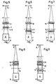
Anhand der Figuren 1 - 9 der beigefügten Zeichnungen, die jeweils schematisch den Lukenstrahlengang verschiedener Mikroskopsysteme vom Objekt bis zum Zwischenbild skizzieren, wird der Erfindungsgedanke näher erläutert:
- Figur 1 skizziert die Abbildung des Objekts mit einem Objektiv endlicher Ausgangsschnittweite;
Figur 2 skizziert die Abbildung mit einem Objektiv unendlicher Ausgangsschnittweite;Figur 3 skizziert die Abbildung mit einem adaptiertem Objektiv unendlicher Ausgangsschnittweite;- Figur 4 skizziert die Abbildung mit einem adaptiertem Objektiv endlicher Ausgangsschnittweite;
Figur 5 skizziert die Abbildung durch ein Objektiv endlicher Ausgangsschnittweite mit Telansystem;Figur 6 skizziert die gleiche Abbildung bei geändeder Tubusoptik und adaptiertem Objektiv endlicher Ausgangsschnittweite;Figur 7 skizziert die gleiche Abbildung wie Fig. 6 jedoch mit adaptiertem Objektiv unendlicher Ausgangsschnittweite;Figur 8 skizziert die gleiche Abbildung wie Fig. 7 mit nochmals geänderter Tubusoptik;- Figur 9 skizziert die gleiche Abbildung wie Fig. 8 mit adaptiertem Objektiv endlicher Ausgangsschnittweite.
- Figure 1 outlines the image of the object with a lens of finite initial focal length;
- Figure 2 outlines the image with an objective of infinite output focal length;
- Figure 3 outlines the image with an adapted lens of infinite output focal length;
- FIG. 4 outlines the image with an adapted lens of finite initial focal length;
- Figure 5 outlines the illustration by a Objective finite output focal length with telansystem;
- FIG. 6 outlines the same illustration with the tube optics changed and the lens with a finite output focal length adapted;
- FIG. 7 outlines the same illustration as FIG. 6 but with an adapted lens of infinite output focal length;
- FIG. 8 outlines the same illustration as FIG. 7 with another modified tube optics;
- FIG. 9 outlines the same illustration as FIG. 8 with an adapted lens of finite initial focal length.
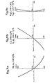
Die Figuren 10 - 16 zeigen Beispieie für den normierten Verlauf der chromatischen Längsabweichung in Abhängigkeit der Wellenlänge für die Objektive, Adapter und Tubuslinsen in den Anordnungan nach den Figuren 1 - 9.FIGS. 10-16 show examples of the normalized course of the chromatic longitudinal deviation as a function of the wavelength for the lenses, adapters and tube lenses in the arrangement according to FIGS. 1-9.
In Fig. 1 erzeugt ein Objektiv 1 endlicher Schnittweite vom Objekts ein mit Farbquerfehler behaftetes Zwischenbild 7 im Endlichen und entspricht damit einem System erster Art. Mit 9 ist die mechanische Begrenzung des Objektivgehäuses bezeichnet.In FIG. 1, a lens 1 of finite focal length from the object produces an
Fig. 2 zeigt dagegen ein Mikroskop-Objektiv 2 mit unendlicher Schnittweite, mit dem das Objekt 6 nach Unendlich abgebildet wird. Ein Tubuslinsensystem 20 mit unterkorrigierter chromatischer Längsabweichung erzeugt das farbfreie Zwischenbild 8 ohne die monochromatischen Bildfehler, die bereits im Objektiv 2 auskorrigiert sind, zu beeinflußen.2, on the other hand, shows a
Die Brechkraft des Tubuslinsensystem 20 ist so gewählt, daß ein Adapter 4 mit dem Betrage nach gleicher aber negativer Brechkraft und gleicher Dispersion mit einem herkömmlichen Objektiv 1, an dessen Gehäuse er befestigt ist, das Objektiv 2 in Fig. 2 ersetzen kann (Fig. 4). Mit Hilfe des Adapters 4, der die Schnittweite herkömmlicher Objektive 1 nach Unendlich verlegt, können diese also an Mikroskoptuben zweiter Art verwendet werden ohne daß sich ihr Abbildungsmaßstab ändert. Das Zwischenbild ist farbfrei.The refractive power of the
Versieht man, wie in Fig. 3 dargestellt, ein Objektiv 2 mit unendlicher Schnittweite mit einem Adapter 3, der dem Adapter 7 (Fig. 4) bis auf das Vorzeichen der Brechkraft entspricht und somit die gleiche Brechkraft wie das Tubuslinsensystem 20 besitzt, dann kann mit dieser Kombination ein Objektiv endlicher Ausgangsschnittweite ebenfalls ohne Änderung des Abbildungsmaßstabes ersetzt werden. Das Zwischenbild 7 besitzt den gleichen Farbquerfehler wie das in Fig. 1, der im Gegensatz zum Farblängsfehler von der Stellung des Adapters 3 (Abstand zur Objektivpupille) abhängt.If, as shown in FIG. 3, an objective 2 with an infinite focal length is provided with an
In dem mit Hilfe der Figuren 1 - 4 skizzierten System ist die Zahl der freien Parameter überschaubar. Da von der Voraussetzung ausgegangen wird, dan beide Objektivklassen U und E bezüglich der monochromatischen Bildfehler auskorrigiert sind und die Brennweite der Adapter 3 und 4 und des Tubuslinsensystems 20 entsprechend den gängigen Werten für verwendete optische Tubuslängen im Dezimeterbereich liegt, kann auf eine Betrachtung der Linsenformen (Radien), die ohne Einfluß auf die chromatischen Bildfehler sind, bei den Adaptern bzw. bei der Tubusoptik verzichtet werden. Die Radien können vielmehr so gewählt werden, daß die Hauptebenen der Adapter bei den verschiedeen Objektiven stets die Lage einnehmen, die zur Erzielung der gewünschten chromatischen Korrektur erforderlich ist, ohne die Adapter selbst in diese Lagen zu bringen.In the system sketched with the aid of FIGS. 1-4, the number of free parameters is manageable. Since it is assumed that both lens classes U and E are corrected for the monochromatic image errors and that the focal length of the
Ausgehend von dem jeweiligen Wert für die Farbquerfehler im Zwischenbild 7 nach Fig. 1 sind somit
- a) die, für die
Adapter 3, 4 und fürdas Tubuslinsensystem 20 vorzugsweise gleiche Dispersion - b) die Lage der Hauptebenen der Adapter und des Tubuslinsensystems
- c) der chromatische Korrekturzustand der Objektive
- a) which, for the
adapter 3, 4 and for thetube lens system 20, preferably the same dispersion - b) the location of the main planes of the adapter and the tube lens system
- c) the chromatic correction state of the lenses
so zu wählen, daß sich für die Anordnungen nach den Figuren 2 und ein chromatisch auskorrigiertes Zwischenbild 8 ergibt und für die Anordnung nach Fig. 3 der gleiche Farbquerfehler im Zwischenbild 7 wie in Fig. 1.to be selected such that the arrangement according to FIGS. 2 and a chromatically corrected
Das geschieht dadurch, daß bei der Auswahl dieser Größen im wesentlichen folgende Beziehung eingehalten wird:
vd = die Abbezahl der bei den Linsen bzw. Kittgliedkomponenten verwendeten Gläser,
f = die Brennweite der jeweiligen Linsen oder Kittgliedkomponenten,
L - die Entfernung ihrer Hauptebenen von der Austrittspupille der in Verbindung mit dem Tubuslinsensystem benutzten Objektive und,
CHV - der zu kompensierende Farbquerfehler dieser Objektive ist.This happens because the following relationship is maintained when selecting these sizes:
v d = the Abbe number of the glasses used for the lenses or cemented component,
f = the focal length of the respective lenses or cemented component,
L - the distance of their main planes from the exit pupil of the lenses used in connection with the tube lens system and,
CHV - is the cross-color error to be compensated for these lenses.
Die Figuren 10 - 14 verdeutlichen dies. Fig. 10 zeigt den normierten Verlauf der chromatischen Längsabweichung (CHL) für ein Objektiv E erster Art (Achromat mit Abbildungsmaßstab 10x, Apertur 0.22, Ausgangsschnittweite 160 mm), dessen Zwischenbild einen Farbvergrößerungsfehler (CHV) von 1,4 % besitzt. Das entsprechende Objektiv U zweiter Art, dessen Verlauf der CHL Fig. 11a zeigt, ist so ausgelegt (CHV = 1,5 %), daß eine positive Einzellinse mit der Brennweite f = 160 mm, deren Verlauf der CHL Fig. 11b zeigt (f = 160 mm, vd = 20,4), als Tubuslinse im Abstand A = 0,45 f von der Objektebene (Fig. 2) die Farbfehler des Objektivs U kompensiert und als Adapter am Objektivgehäuse (Fig. 3) ein Zwischenbild mit einer CHV von 1,4 % erzeugt.Figures 10-14 illustrate this. 10 shows the normalized course of the chromatic longitudinal deviation (CHL) for an objective E of the first kind (achromatic with 10x magnification, aperture 0.22, initial focal length 160 mm), the intermediate image of which has a color magnification error (CHV) of 1.4%. The corresponding objective U of the second type, the course of which is shown in CHL Fig. 11a, is designed (CHV = 1.5%) so that a positive single lens with a focal length f = 160 mm, the course of which is shown in CHL Fig. 11b (f = 160 mm, v d = 20.4), as a tube lens at a distance A = 0.45 f from the object plane (FIG. 2) compensates for the color errors of the lens U and as an adapter on the lens housing (FIG. 3) an intermediate image with a CHV generated by 1.4%.
Den resultierenden Verlauf der CHL, der wegen des parallelen Strahlenganges von der Stellung der Linse unabhängig ist, zeigt Fig. 11 c. Der Abbildungsmaßstab und die Apertur des Objektivs U stimmen mit den entsprechenden Werten des Objektivs E überein.The resulting course of the CHL, which is due to the parallel beam path from the position the lens is independent, Fig. 11 c shows. The image scale and the aperture of the lens U agree with the corresponding values of the lens E.
Wählt man bei der Projektierung der Objektive U andere chromatische Korrekturzustände, wie z. B. in Fig. 12 oder Fig. 13 dargestellt, dann kann bei Verwendung geeigneten Materials für den Adapter 3 und die Tubuslinse 20 (vd = 41,5 für Fig. 12b; vd = 84,5 für Fig. 13b) sowie deren Steilung (L = 105 mm in Fig. 12b; L = 220 mm in Fig. 13b) unter Beibehaltung der Brennweite (f = 160 mm) doch jeweils die gewünschte Zwischenbildkorrektur im Sinne der Kompatibilität mit dem nach Fig. 10 korrigierten Objektiv E erzielt werden. Im Rahmen von Gleichung 1 können natürlich auch andere Parameter, z. B. L, vorgegeben werden und die Objektive U für das Optiksystem entsprechend berechnet werden. Ergeben sich zum Kompensieren der CHV mittels Einzellinsen (i = 1) Werte für die Dispersion, die mit zur Zeit bekannten Gläsern nicht erreicht werden, dann sind die Adapter und die Tubuslinse z. B. als Kittglieder so zu dimensionieren, daß sich das gewünschte dispersive Verhalten ergibt.If you choose other chromatic correction states when configuring the U lenses, such as As shown in Fig. 12 or Fig. 13, then when using suitable material for the
Fig. 14 beschreibt die chromatische Korrektur des in Fig. 4 dargestellten Systems. Dabei kompensieren sich die Farblängsfehler 30 des negativen Adapters 4 und die Farblängsfehler 40 der positiven Tubuslinse 20 aufgrund ihrer gleichen Dispersion (vd = 41,5) so daß als Resultat in Fig. 14c der gleiche Verlauf der CHL wie in Fig. 14a bzw. Fig. 10 vorliegt. Der Farbquerfehler (CHV) im Zwischenbild nach Fig. 14c wird zu Null, da der geringe Beitrag des in der Nähe der Objektivpupille angebrachten Adapters 4 zur CHV im Vergleich zum positiven Adapter 3 in Fig. 12b mit umgekehrten Vorzeichen eingeht und somit die Differenz in der CHV beider Objektivtypen E und U ausgeglichen wird.FIG. 14 describes the chromatic correction of the system shown in FIG. 4. The longitudinal
Die Werte für die CHV in den Figuren 11 - 14 lassen sich alle aus Gleichung 1 barechnen, wenn berücksichtigt wird, daß die Adapter 3 und 4 etwa einen Abstand von 10 mm von der Objektivpupille besitzen.The values for the CHV in FIGS. 11-14 can all be calculated from equation 1 if it is taken into account that the
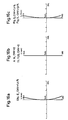
In den Figuren 5 - 7 wird die Erzielung gegensetiger Kompatibilität der vorstehend beschriebenen Systeme mit Hilfe eines achromatischen negativen Adapters 14 und eines weiteren afokalen Adapters 5 skizziert, wobei davon ausgegangen wird, daß das System erster Art ein sog. Telansystem enthält, das den Objekt-Bildabstand mit Hilfe eines positiven (10) und negativen (11) achromatischen Gliedes an die Stativabmessungen anpaßt. Da die Verwendung von Objektiven E an neuen Tuben zweiter Art mit Hilfe des negativen Adapters 4 in Fig. 4 bereits skizziert wurde, wird nur noch die Austauschbarkeit der beiden Objektivtypen E und U an Tuben des Systems erster Art gezeigt.FIGS. 5-7 outline the achievement of mutual compatibility of the systems described above with the aid of an achromatic
Dazu empfiehlt es sich, das negative Glied 11 des Telansystems aus dem auf Objektive erster Art zugeschnittenen Tubus zu entfernen (Bild 6). Am Gehäuse des Objektivs 1 ist jetzt ein negativer achromatischer Adapter 14 angebracht, der den ursprünglichen Zustand nach Bild 5 wieder herstellt.To do this, it is advisable to remove the
Mit diesem teilentleerten Tubus kann jedoch ein Objektiv zweiter Art unter Verwendung eines afokalen Adapters 5 kombiniert werden (Bild 7), der das gleiche dispersive Verhalten wie der Adapter 3 in Fig. 3 besitzt. In Verbindung mit dem achromatischen positiven Glied 10 des ursprünglichen Telansystems erhält man wieder ein Zwischenbild 7 mit Farbquerfehler.With this partially emptied tube, however, a lens of the second type can be combined using an afocal adapter 5 (FIG. 7), which has the same dispersive behavior as the
Eine weitere sinnvolle Möglichkeit, die Objektive E und U an einen derartigen Tubus zu adaptieren zeigen Bild 8 und 9. Hier wird das afokale Glied 15 mit den dispersiven Eigenschaften des Adapters 5 im Tubus in der Nähe des achromatischen Gliedes 10 angeordnet. Dieses System besitzt hinsichtlich seiner optischen Wirkung den gleichen Aufbau wie das in Fig. 2 und 4 skizzierte und unterscheidet sich lediglich dadurch, daß Brechkraft und Dispersion der Tubuslinse 20 in Fig. 2 und 4 durch die getrennten Glieder 10 und 15 aufgebracht werden.A further sensible possibility of adapting the objectives E and U to such a tube is shown in FIGS. 8 and 9. Here the
An derart umgestalteten Tuben des Systems erster Art lassen sich, wie Fig. 8 zeigt, Objektive U zweiter Art ohne Adapter (Fig. 8) und Objektive E mit dem hinsichtlich seiner chromatischen Längsabweichung überkorrigierten Adapter 4 (Fig. 9) verwenden. Das resultierende Zwischenbild ist hier in Fig. 2 und 4 farbfrei.8, lenses U of the second type without an adapter (FIG. 8) and lenses E with the adapter 4 (FIG. 9) overcorrected in terms of its chromatic longitudinal deviation can be used on tubes of the system of the first type which have been redesigned in this way. The resulting intermediate image is color-free in FIGS. 2 and 4.
Diese auf den arsten Blick umständliche Lösung, bei der statt einer Einzellinse mit gleicher Wirkung 2 Kittglieder benutzt werden, hat jedoch den Vorteil, daß chromatische Korrekturen im Zwischenbild vorgenommen werden können, ohne dessen Lage zu beeinflussen. Insbesondere ist eine auswechselbare Befestigung des Gliedes 15 möglich, so daß an einem Tubus mit dem gleichen Objektiv beide Korrekturzustände des Zwischenbildes nach Fig. 6 bzw. 7 oder nach Fig. 8 bzw. 9 realisiert werden können.This solution, which at first sight is cumbersome, in which two cemented elements are used instead of a single lens with the same effect, has the advantage, however, that chromatic corrections can be made in the intermediate image without affecting its position. In particular, an exchangeable attachment of the
Durch achsiales Verschieben des Gliedes 15 läßt sich der Farbquerfehler im Zwischenbild 8 auf einfache Weise völlig kompensieren, wodurch ohne Verstellung der Schärfenebene kleine Differenzen im Korrekturzustand verschiedener Objektive oder Fertigungstoleranzen ausgeglichen werden können. Zur Realisierung dieser besonders für die Farbfotographie mikroskopischer Objekte interessanten Möglichkeit sind am Tubus Einstellelemente vorhanden, mit den sich die besagte Längsverschiebung des Gliedes 15 reproduzierbar und kontinuierlich durchführen läßt. Natürlich ist die Verwendung eines derartigen Elements nicht nur in Verbindung mit dem vorstehend skizzierten Optiksystem möglich. Auch ohne Adapter vorzusehen, mit denen Objektive erster und zweiter Art kompatibel gemacht werden, (z. B. für nicht kompatibte Spezialmikroskope) ist der Einsatz von Justierelementen zur völligen Eliminierung des Farbquerfehlers im Zwischenbild denkbar und sinnvoll.By shifting the
Die mit Hilfe der Figuren 10 - 14 illustrierten Korrektuwirkungen der Adapter für die Anordnungen nach den Figuren 1 - 4 können ohne Schwierigkeiten auf die Anordnungen nach den Figuren 5 - 9 übertragen werden.The corrective effects of the adapters for the arrangements according to FIGS. 1-4, illustrated with the aid of FIGS. 10-14, can be transferred to the arrangements according to FIGS. 5-9 without difficulty.
Dazu zeigt Fig. 16a nochmals den Verlauf der CHL des Objektivs E wie in Fig. 10. Die in Fig. 5 und 6 skizzierte achromatische Tubusoptik 11, 10 bzw. der Adapter 14 bleiben nahezu ohne Einfluß auf den Farbquerfehler (Fig. 16b), so daß für beide Fälle der in Fig. 16c dargestellte Verlauf der CHL resultiert, der im wesentlichen mit Fig. 16a übereinstimmt.16a again shows the course of the CHL of the objective E as in FIG. 10. The
Fig. 15 zeigt dagegen die Kompensation der Farbfehler des Objektivs U gemäß einer Anordnung nach Fig. 7 durch den Adapter 5 (Fig. 15b), der bei gleicher Stellung wieder Adapter 3 in Fig. 3 und bei gleichem dispersiven Verhalten (vergleiche Fig. 12b) das in Fig. 15c dargestellte Resultat mit einer Farbquerfehler von 1,4 % ergibt. Der Adapter 5 besteht aus einer positiven Linse (f - 46,5 mm; vd = 33,8) und einer negativen Linse (f - -46,5; vd = 46,5), die miteinander verkittet sind.FIG. 15, on the other hand, shows the compensation of the color errors of the lens U according to an arrangement according to FIG. 7 by the adapter 5 (FIG. 15b), the
Die Anordnung nach Fig. 8, in der das aus dem gleichen Kittglied wie der Adapter 5 bestehende nun zum Tubuslinsensystem gehörende Glied 15 für ein farbfreies Zwischenbild 8 sorgt, ist ebenfalls durch die Fig. 15 beschrieben. Der im Vergleich zu Fig. 7 von ca. 10 mm auf ca. 105 mm geänderte Wert für L wirkt sich nicht auf den Verlauf der CHL aus, da sich der Adapter 5 bzw. das Tubuslinsensystem 15 im Bereich parallelen Strahlenganges befinden; es ergibt sich also wieder der Verlauf der CHL nach Fig. 15b während die CHV des Objektivs 2 in diesem Falle völlig kompensiert wird (vergleiche Gleichung 1).The arrangement according to FIG. 8, in which the
Für die Korrektur des Objektivs U in Fig. 9 ist die Darstellung nach Fig. 14 zu übernehmen, wobei dort der Graph 40 durch den nahezu identischen Graphen in Fig. 15b ersetzt wird. Der Einfluß der achromatischen Tubuslinse 10 (vergleiche Fig. 16b) kann vernachlässigt werden, so daß sich auch für die Anordnung nach Fig. 9 der in Fig. 14c skizzierte Verlauf der CHL ergibt.For the correction of the lens U in FIG. 9, the illustration according to FIG. 14 is to be adopted, the graph 40 being replaced there by the almost identical graph in FIG. 15b. The influence of the achromatic tube lens 10 (cf. FIG. 16b) can be neglected, so that the course of the CHL sketched in FIG. 14c also results for the arrangement according to FIG. 9.
Claims (7)
characterized by the fact that in order to achieve mutual compatibility of the two types of objective

characterized by the fact that in order to achieve mutual compatibility of the two types of objective (1, 2)

Priority Applications (1)
| Application Number | Priority Date | Filing Date | Title |
|---|---|---|---|
| AT80102638T ATE937T1 (en) | 1979-05-17 | 1980-05-13 | OPTIC SYSTEM FOR MICROSCOPES. |
Applications Claiming Priority (2)
| Application Number | Priority Date | Filing Date | Title |
|---|---|---|---|
| DE2919924A DE2919924C2 (en) | 1979-05-17 | 1979-05-17 | Optical system for microscopes |
| DE2919924 | 1979-05-17 |
Publications (3)
| Publication Number | Publication Date |
|---|---|
| EP0019263A1 EP0019263A1 (en) | 1980-11-26 |
| EP0019263B1 EP0019263B1 (en) | 1982-04-28 |
| EP0019263B2 true EP0019263B2 (en) | 1988-08-31 |
Family
ID=6070959
Family Applications (1)
| Application Number | Title | Priority Date | Filing Date |
|---|---|---|---|
| EP80102638A Expired EP0019263B2 (en) | 1979-05-17 | 1980-05-13 | Microscope lens system |
Country Status (6)
| Country | Link |
|---|---|
| US (1) | US4365871A (en) |
| EP (1) | EP0019263B2 (en) |
| JP (1) | JPS55155319A (en) |
| AT (1) | ATE937T1 (en) |
| BR (1) | BR8003053A (en) |
| DE (1) | DE2919924C2 (en) |
Families Citing this family (15)
| Publication number | Priority date | Publication date | Assignee | Title |
|---|---|---|---|---|
| JPS58102207A (en) * | 1981-12-14 | 1983-06-17 | Nippon Kogaku Kk <Nikon> | Telecentric rear converter |
| JPH01154016A (en) * | 1987-12-10 | 1989-06-16 | Nikon Corp | Microscope |
| US5002376A (en) * | 1989-05-15 | 1991-03-26 | Edward Weck Incorporated | Dual stereomicroscope |
| US5307203A (en) * | 1990-12-06 | 1994-04-26 | Tandem Scanning Corporation | Confocal tandem scanning reflected light microscope |
| US5161052A (en) * | 1991-03-29 | 1992-11-03 | Tandem Scanning Corporation | Steroscopic tandem scanning reflected light confocal microscope |
| US5239416A (en) * | 1992-06-29 | 1993-08-24 | Optical Designs, Inc. | Variable power zoom stand magnifier |
| DE19513870C2 (en) * | 1995-04-12 | 2001-05-10 | Zeiss Carl Jena Gmbh | Binocular microscope |
| JP3123457B2 (en) * | 1996-05-13 | 2001-01-09 | 株式会社ニコン | microscope |
| JPH1195118A (en) | 1997-09-22 | 1999-04-09 | Olympus Optical Co Ltd | Conversion optical system |
| DE10130621B4 (en) * | 2001-06-26 | 2005-07-28 | Carl Zeiss Jena Gmbh | microscope |
| TW200532278A (en) | 2003-08-15 | 2005-10-01 | E Vision Llc | Enhanced electro-active lens system |
| DE102004009848A1 (en) * | 2004-02-28 | 2005-09-15 | Carl Zeiss Jena Gmbh | Tubular lens unit with chromatic correction capacity for ICS systems, has specifically defined chromatic length and magnification deviation values |
| DE102014005501A1 (en) * | 2013-10-08 | 2015-04-09 | Carl Zeiss Microscopy Gmbh | tube lens |
| CN104122661B (en) * | 2014-08-19 | 2017-03-01 | 重庆奥特光学仪器有限责任公司 | Optics in Microscope image infinity parfocalization correcting unit and bearing calibration |
| DE102019211360A1 (en) * | 2019-07-30 | 2021-02-04 | Carl Zeiss Microscopy Gmbh | Tube system |
Family Cites Families (10)
| Publication number | Priority date | Publication date | Assignee | Title |
|---|---|---|---|---|
| US1446634A (en) * | 1921-01-04 | 1923-02-27 | Bell Louis | Photographic lens |
| DE886393C (en) | 1942-08-02 | 1953-08-13 | Leitz Ernst Gmbh | Additional system to compensate for the chromatic magnification difference of the imaging systems of a microscope |
| SU122304A1 (en) * | 1954-01-21 | 1958-11-30 | Б.Л. Нефедов | Afoka system |
| US3132200A (en) * | 1961-06-05 | 1964-05-05 | American Optical Corp | Microscope optical system |
| US3437398A (en) * | 1964-02-10 | 1969-04-08 | American Optical Corp | Plural microscope objective used with a common telescope objective |
| GB1102385A (en) * | 1964-11-04 | 1968-02-07 | Bausch & Lomb | Optical system for microscopes |
| US3481665A (en) * | 1968-05-02 | 1969-12-02 | Bausch & Lomb | Multi-powered micro-objective group having common aberration correcting means |
| DE1910550A1 (en) * | 1969-03-01 | 1970-09-17 | Leitz Ernst Gmbh | Stereo microscope |
| US3790255A (en) * | 1972-09-11 | 1974-02-05 | American Optical Corp | Zoom lens system |
| LU79603A1 (en) | 1978-05-05 | 1979-12-06 | Angenieux P Ets | DEVICE FOR ADJUSTING THE VALUE OF THE CHROMATISMO ABERRATIONS OF AN OPTICAL SYSTEM AND METHOD INCLUDING THE APPLICATION OF SUCH A DEVICE FOR ADJUSTING COLOR TELEVISION CAMERAS USING A DIASCOPE |
-
1979
- 1979-05-17 DE DE2919924A patent/DE2919924C2/en not_active Expired
-
1980
- 1980-05-12 US US06/148,820 patent/US4365871A/en not_active Expired - Lifetime
- 1980-05-13 EP EP80102638A patent/EP0019263B2/en not_active Expired
- 1980-05-13 AT AT80102638T patent/ATE937T1/en not_active IP Right Cessation
- 1980-05-16 JP JP6418480A patent/JPS55155319A/en active Granted
- 1980-05-16 BR BR8003053A patent/BR8003053A/en unknown
Also Published As
| Publication number | Publication date |
|---|---|
| ATE937T1 (en) | 1982-05-15 |
| BR8003053A (en) | 1980-12-23 |
| EP0019263A1 (en) | 1980-11-26 |
| EP0019263B1 (en) | 1982-04-28 |
| US4365871A (en) | 1982-12-28 |
| JPS55155319A (en) | 1980-12-03 |
| DE2919924A1 (en) | 1980-11-20 |
| DE2919924C2 (en) | 1982-11-11 |
| JPS6217723B2 (en) | 1987-04-20 |
Similar Documents
| Publication | Publication Date | Title |
|---|---|---|
| EP0019263B2 (en) | Microscope lens system | |
| EP2312370B1 (en) | Camera adapter with camera holder and lens adapter | |
| DE4417489A1 (en) | High-aperture catadioptric reduction lens for microlithography | |
| DE19837135C5 (en) | Afocal zoom system | |
| DE102014112199A1 (en) | Microscopic imaging system | |
| DE3318011C2 (en) | Additional device for stereo microscopes | |
| DE102015103707A1 (en) | Projection lens and projection type display device | |
| DE102012006749B4 (en) | Stereo microscope | |
| DE4344366C2 (en) | Optical system with variable image scale | |
| EP2853933B1 (en) | Optical imaging system | |
| EP1025460B1 (en) | MICROSCOPE EYEPIECE WITH 10x MAGNIFICATION | |
| EP2894507B1 (en) | Telescope with prism inversion system | |
| DE2336823C2 (en) | Varifocal lens | |
| DE102015225641A1 (en) | zoom lens | |
| EP2916161A1 (en) | Back focus extender | |
| DE2310474A1 (en) | MACRO LENS | |
| DE10036309A1 (en) | Catadioptric lens e.g. for astronomy has two positive lenses and reflectors with parameters set to avoid image distortion | |
| DE2144941A1 (en) | Varifocal lens | |
| EP2616867B1 (en) | Microscope objective having large working distance | |
| DE4107070A1 (en) | Two-part flame chromate lens unit - has thick fluorspar-glass collector lens between twin-lens sets | |
| DE2036285A1 (en) | Pancratic projection lens | |
| DE2954055C2 (en) | Imaging optical system for microscopes with an adjustment element for setting the lateral color aberration | |
| DE2300742C3 (en) | Device for enlarging part of the field of view of optical devices | |
| DE2556890B2 (en) | Magnifying lens, in particular for copier purposes | |
| DE102004033967B3 (en) | Microscope with image brightness adjustment |
Legal Events
| Date | Code | Title | Description |
|---|---|---|---|
| PUAI | Public reference made under article 153(3) epc to a published international application that has entered the european phase |
Free format text: ORIGINAL CODE: 0009012 |
|
| 17P | Request for examination filed | ||
| AK | Designated contracting states |
Designated state(s): AT CH FR GB |
|
| GRAA | (expected) grant |
Free format text: ORIGINAL CODE: 0009210 |
|
| AK | Designated contracting states |
Designated state(s): AT CH FR GB |
|
| REF | Corresponds to: |
Ref document number: 937 Country of ref document: AT Date of ref document: 19820515 Kind code of ref document: T |
|
| PLBI | Opposition filed |
Free format text: ORIGINAL CODE: 0009260 |
|
| 26 | Opposition filed |
Opponent name: ERNST LEITZ WETZLAR GMBH Effective date: 19830127 |
|
| PGFP | Annual fee paid to national office [announced via postgrant information from national office to epo] |
Ref country code: FR Payment date: 19840517 Year of fee payment: 5 |
|
| PLAB | Opposition data, opponent's data or that of the opponent's representative modified |
Free format text: ORIGINAL CODE: 0009299OPPO |
|
| R26 | Opposition filed (corrected) |
Opponent name: ERNST LEITZ WETZLAR GMBH Effective date: 19830127 |
|
| PG25 | Lapsed in a contracting state [announced via postgrant information from national office to epo] |
Ref country code: GB Effective date: 19880513 |
|
| PUAH | Patent maintained in amended form |
Free format text: ORIGINAL CODE: 0009272 |
|
| STAA | Information on the status of an ep patent application or granted ep patent |
Free format text: STATUS: PATENT MAINTAINED AS AMENDED |
|
| 27A | Patent maintained in amended form |
Effective date: 19880831 |
|
| AK | Designated contracting states |
Kind code of ref document: B2 Designated state(s): AT CH FR GB |
|
| EN3 | Fr: translation not filed ** decision concerning opposition | ||
| PG25 | Lapsed in a contracting state [announced via postgrant information from national office to epo] |
Ref country code: FR Free format text: LAPSE BECAUSE OF NON-PAYMENT OF DUE FEES Effective date: 19890131 |
|
| GBPC | Gb: european patent ceased through non-payment of renewal fee | ||
| REG | Reference to a national code |
Ref country code: FR Ref legal event code: ST |
|
| PGFP | Annual fee paid to national office [announced via postgrant information from national office to epo] |
Ref country code: AT Payment date: 19920525 Year of fee payment: 13 |
|
| PG25 | Lapsed in a contracting state [announced via postgrant information from national office to epo] |
Ref country code: AT Effective date: 19930513 |
|
| PGFP | Annual fee paid to national office [announced via postgrant information from national office to epo] |
Ref country code: CH Payment date: 19940420 Year of fee payment: 15 |
|
| PG25 | Lapsed in a contracting state [announced via postgrant information from national office to epo] |
Ref country code: LI Effective date: 19950531 Ref country code: CH Effective date: 19950531 |
|
| REG | Reference to a national code |
Ref country code: CH Ref legal event code: PL |
|
| APAH | Appeal reference modified |
Free format text: ORIGINAL CODE: EPIDOSCREFNO |