EP0018892B1 - Dispositif d'étanchéité entre deux éléments de turbomachine - Google Patents
Dispositif d'étanchéité entre deux éléments de turbomachine Download PDFInfo
- Publication number
- EP0018892B1 EP0018892B1 EP80400555A EP80400555A EP0018892B1 EP 0018892 B1 EP0018892 B1 EP 0018892B1 EP 80400555 A EP80400555 A EP 80400555A EP 80400555 A EP80400555 A EP 80400555A EP 0018892 B1 EP0018892 B1 EP 0018892B1
- Authority
- EP
- European Patent Office
- Prior art keywords
- assembly
- annular member
- members
- combustion chamber
- coefficient
- Prior art date
- Legal status (The legal status is an assumption and is not a legal conclusion. Google has not performed a legal analysis and makes no representation as to the accuracy of the status listed.)
- Expired
Links
- 238000007789 sealing Methods 0.000 title claims description 17
- 238000002485 combustion reaction Methods 0.000 claims description 23
- 239000000463 material Substances 0.000 claims description 9
- 239000007789 gas Substances 0.000 claims description 4
- 238000011144 upstream manufacturing Methods 0.000 claims description 3
- 230000000712 assembly Effects 0.000 claims description 2
- 238000000429 assembly Methods 0.000 claims description 2
- 230000000284 resting effect Effects 0.000 claims 4
- 238000006073 displacement reaction Methods 0.000 description 3
- 238000001816 cooling Methods 0.000 description 2
- 238000004519 manufacturing process Methods 0.000 description 2
- 230000001052 transient effect Effects 0.000 description 2
- 239000011324 bead Substances 0.000 description 1
- 239000000567 combustion gas Substances 0.000 description 1
- 230000006835 compression Effects 0.000 description 1
- 238000007906 compression Methods 0.000 description 1
- 230000008602 contraction Effects 0.000 description 1
- 238000005516 engineering process Methods 0.000 description 1
- 238000000034 method Methods 0.000 description 1
- 230000005012 migration Effects 0.000 description 1
- 238000013508 migration Methods 0.000 description 1
- 238000012986 modification Methods 0.000 description 1
- 230000004048 modification Effects 0.000 description 1
- 210000000056 organ Anatomy 0.000 description 1
Images
Classifications
-
- F—MECHANICAL ENGINEERING; LIGHTING; HEATING; WEAPONS; BLASTING
- F01—MACHINES OR ENGINES IN GENERAL; ENGINE PLANTS IN GENERAL; STEAM ENGINES
- F01D—NON-POSITIVE DISPLACEMENT MACHINES OR ENGINES, e.g. STEAM TURBINES
- F01D11/00—Preventing or minimising internal leakage of working-fluid, e.g. between stages
- F01D11/005—Sealing means between non relatively rotating elements
-
- F—MECHANICAL ENGINEERING; LIGHTING; HEATING; WEAPONS; BLASTING
- F01—MACHINES OR ENGINES IN GENERAL; ENGINE PLANTS IN GENERAL; STEAM ENGINES
- F01D—NON-POSITIVE DISPLACEMENT MACHINES OR ENGINES, e.g. STEAM TURBINES
- F01D9/00—Stators
- F01D9/02—Nozzles; Nozzle boxes; Stator blades; Guide conduits, e.g. individual nozzles
- F01D9/023—Transition ducts between combustor cans and first stage of the turbine in gas-turbine engines; their cooling or sealings
-
- F—MECHANICAL ENGINEERING; LIGHTING; HEATING; WEAPONS; BLASTING
- F02—COMBUSTION ENGINES; HOT-GAS OR COMBUSTION-PRODUCT ENGINE PLANTS
- F02C—GAS-TURBINE PLANTS; AIR INTAKES FOR JET-PROPULSION PLANTS; CONTROLLING FUEL SUPPLY IN AIR-BREATHING JET-PROPULSION PLANTS
- F02C7/00—Features, components parts, details or accessories, not provided for in, or of interest apart form groups F02C1/00 - F02C6/00; Air intakes for jet-propulsion plants
- F02C7/28—Arrangement of seals
Definitions
- the subject of the present invention is a sealing device between two turbomachine elements, traversed by gases, in particular between a combustion chamber and a high pressure distributor support, this device comprising an independent ferrule supported by bearing surfaces respectively on the elements to be tightly connected, the two turbomachine elements being substantially coaxial and axially spaced to constitute a first assembly, and said ferrule constituting a second assembly extending coaxially to the first assembly over a length greater than that of the space separating the two elements of the first set.
- the members at the junction of the turbine distributor and the combustion chamber most often have significant radial and axial relative displacements. These displacements are generally created mainly by the differences in temperature of the organs in transient operation and by the differences in expansion coefficients of the materials.
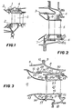
- Sealing is generally ensured by a “fork” assembly device, as shown in 1 and 2 in FIG. 1 which represents an extract in longitudinal section of a turbomachine whose combustion chamber 3 is connected to the distributor support casing 4 by said assembly device.
- This "fork” assembly device imposes tight adjustment tolerances without, however, in most cases, it is possible to completely control the operating clearances of the elements present and therefore control the leakage rates.
- GB-A-1 126 468 discloses an annular manifold for combustion gases using a fork device of the type described in FIG. 1 to connect a ferrule welded internally on the combustion chamber to the structure supporting the high-pressure distributor. pressure.
- This ferrule which is not independent, is connected, by welded axial bands, to another fixed ferrule placed internally. Materials with different coefficient of expansion are used to make the two ferrules and the axial bands respectively, in order to keep the jacket of the combustion chamber, the rotor and the crown of stator blades concentric, during thermal expansion in operation .
- the aim of the improved sealing device according to the invention is to remedy these drawbacks.
- the sealing device is characterized in that the ferrule is made of a material whose coefficient of thermal expansion differs from that of the elements constituting the first assembly so that that of the assemblies which is placed externally present a coefficient of thermal expansion lower than that of the assembly placed inside and produced thereon, at operating temperature a clamping force by means of radial bearing surfaces of the ferrule, bearing respectively on the elements to connect tightly.
- the assembly placed externally is constituted by the ferrule bearing by bearings on the elements of the first assembly, the ferrule being made of a material whose coefficient of thermal expansion is lower than that of the elements of the first set.
- This ferrule in operation provides compression over the entire periphery of the high pressure distributor support upstream, and on a flange downstream of the chamber, and therefore provides an effective seal against hot gases and cooling air.
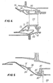
- FIG 3 there is shown a part of a turbomachine to the right of the high pressure distributor and which comprises a turbine casing 8 which is secured by a flange 9 and a flange 10 to a casing 11 of a combustion chamber 12 which includes an internal mixer 13 provided with a ferrule 14 and an external mixer 15 provided with a ferrule 16.
- the ferrule 14 of the internal mixer 13 is secured at 17 with a labyrinth holder 18 on which is fixed a lower heel 19 d a vane 20 of the high pressure distributor, said lower heel having two bearing surfaces 21, 2la forming a seal with flanges 22, 22a of the labyrinth holder 18.
- the blade 20 has an upper bead 23 having two bearing surfaces 24, 24a which form a seal with flanges 25, 25a of a support casing 30 connected to the turbine casing 8.
- a shell 26 of conical shape which has a spherical bearing 27 to 1 downstream bearing on a bearing surface of the distributor support 30 and a spherical bearing 28 upstream bearing on a part 29 of the shell 16 of the external mixer 15.
- the sealing ring 26 can also have a cylindrical or spherical shape, just as the bearing surfaces 27, 28 can be cylindrical.
- the ferrule 26 has a low coefficient of expansion, lower than that of the ferrule 16 of the external mixer and of the distributor support 30.
- the ferrule 26 is mounted with a certain clearance on the bearing surface of the distributor support 30 and of the flange 29 of the combustion chamber; the shoulders 41, 42 have the function of limiting the axial sliding of the ferrule 26 and of opposing an accidental dislocation.
- the relative contraction of the ferrule 26 relative to the distributor support 30 and the flange 29 of the combustion chamber on the other hand, can be perfectly homogeneous, the ring deforming concentrically to itself.
- the assembly can be carried out hot, so that the ferrule 26 is expanded and then shrunk onto the diameters of the distributor and of the chamber.
- the clearances are calculated to allow sliding mounting of the ferrule 26 on the distributor and of the chamber in the ferrule.
- the sealing ring 26 is slid over the cylindrical surface of the distributor support 30; the flange 29 of the combustion chamber is then fitted into the internal diameter of the ferrule 26. Finally, the flanges 9 and 10 of the casing are secured by bolting.
- the seal is imperfect at start-up, but the distributor 20 and the combustion chamber expand very quickly, the ferrule 26 closes quickly and ensures the seal.
- FIG 4 there is shown an alternative embodiment of the sealing device, in which apart from the ferrule .26 disposed between the external mixer 15 and the support 30 of the dispenser, there is provided another ferrule 31 disposed against the internal mixer 13 of the combustion chamber and a flange 32 integral with the labyrinth holder 18.
- a ferrule 33 is disposed internally to the bearing surfaces of the distributor support 30 and to the external mixer 15 of the combustion chamber.
- the shell 33 has a coefficient of expansion greater than that of the two elements 15 and 30 which it combines.
- the shell 33 is provided with bearing surfaces 34 and 35 and abutments 36, 37, bearing against the combustion chamber and the distributor support 30.
Landscapes
- Engineering & Computer Science (AREA)
- Mechanical Engineering (AREA)
- General Engineering & Computer Science (AREA)
- Chemical & Material Sciences (AREA)
- Combustion & Propulsion (AREA)
- Turbine Rotor Nozzle Sealing (AREA)
Applications Claiming Priority (2)
| Application Number | Priority Date | Filing Date | Title |
|---|---|---|---|
| FR7911527 | 1979-05-02 | ||
| FR7911527A FR2455674A1 (fr) | 1979-05-02 | 1979-05-02 | Dispositif d'etancheite entre deux elements de turbomachine |
Publications (2)
| Publication Number | Publication Date |
|---|---|
| EP0018892A1 EP0018892A1 (fr) | 1980-11-12 |
| EP0018892B1 true EP0018892B1 (fr) | 1983-05-11 |
Family
ID=9225157
Family Applications (1)
| Application Number | Title | Priority Date | Filing Date |
|---|---|---|---|
| EP80400555A Expired EP0018892B1 (fr) | 1979-05-02 | 1980-04-24 | Dispositif d'étanchéité entre deux éléments de turbomachine |
Country Status (4)
| Country | Link |
|---|---|
| US (1) | US4398864A (enExample) |
| EP (1) | EP0018892B1 (enExample) |
| DE (1) | DE3063054D1 (enExample) |
| FR (1) | FR2455674A1 (enExample) |
Cited By (1)
| Publication number | Priority date | Publication date | Assignee | Title |
|---|---|---|---|---|
| FR2972760A1 (fr) * | 2011-03-16 | 2012-09-21 | Snecma | Anneau de carter de turbomachine |
Families Citing this family (10)
| Publication number | Priority date | Publication date | Assignee | Title |
|---|---|---|---|---|
| US4640092A (en) * | 1986-03-03 | 1987-02-03 | United Technologies Corporation | Combustion chamber rear outer seal |
| US4859143A (en) * | 1987-07-08 | 1989-08-22 | United Technologies Corporation | Stiffening ring for a stator assembly of an axial flow rotary machine |
| US5149250A (en) * | 1991-02-28 | 1992-09-22 | General Electric Company | Gas turbine vane assembly seal and support system |
| GB9305012D0 (en) * | 1993-03-11 | 1993-04-28 | Rolls Royce Plc | Sealing structures for gas turbine engines |
| US6116013A (en) * | 1998-01-02 | 2000-09-12 | Siemens Westinghouse Power Corporation | Bolted gas turbine combustor transition coupling |
| GB0108398D0 (en) * | 2001-04-04 | 2001-05-23 | Siemens Ag | Seal element for sealing a gap and combustion turbine having a seal element |
| US7238003B2 (en) * | 2004-08-24 | 2007-07-03 | Pratt & Whitney Canada Corp. | Vane attachment arrangement |
| US8474267B2 (en) * | 2009-03-05 | 2013-07-02 | Hamilton Sundstrand Corporation | Radial turbine engine floating ring seal |
| PL415534A1 (pl) | 2016-01-04 | 2017-07-17 | General Electric Company | Układ dla zespołu osłony i przegrody wstępnych łopatek kierowniczych |
| CN114483322B (zh) * | 2021-12-29 | 2023-09-19 | 中国航发长春控制科技有限公司 | 一种具有温度补偿功能的航空发动机起动引气装置 |
Family Cites Families (11)
| Publication number | Priority date | Publication date | Assignee | Title |
|---|---|---|---|---|
| US1313649A (en) * | 1919-08-19 | Elastic-fluid turbine | ||
| NL202529A (enExample) * | 1954-12-16 | |||
| GB1126468A (en) * | 1964-09-25 | 1968-09-05 | English Electric Co Ltd | Improvements relating to turbines |
| DE1426864A1 (de) * | 1965-08-17 | 1969-03-27 | Siemens Ag | Dichtungsanordnung fuer Waermekraftmaschinen |
| US3497046A (en) * | 1967-09-27 | 1970-02-24 | Horton Mfg Co Inc | Rotary seal for clutch and brake members having relative rotation and reciprocation |
| US3841643A (en) * | 1972-01-21 | 1974-10-15 | N Mclean | Seal for bearings and similar rotating members |
| FR2228967A1 (enExample) * | 1973-05-12 | 1974-12-06 | Rolls Royce | |
| IT1022363B (it) * | 1973-10-01 | 1978-03-20 | Gen Electric | Anello di tenuta precaricato |
| GB1493913A (en) * | 1975-06-04 | 1977-11-30 | Gen Motors Corp | Turbomachine stator interstage seal |
| SE398659B (sv) | 1976-05-05 | 1978-01-09 | Stal Laval Turbin Ab | Tetningsanordning i en gasturbin |
| US4184689A (en) * | 1978-10-02 | 1980-01-22 | United Technologies Corporation | Seal structure for an axial flow rotary machine |
-
1979
- 1979-05-02 FR FR7911527A patent/FR2455674A1/fr active Granted
-
1980
- 1980-04-24 DE DE8080400555T patent/DE3063054D1/de not_active Expired
- 1980-04-24 EP EP80400555A patent/EP0018892B1/fr not_active Expired
- 1980-04-30 US US06/145,022 patent/US4398864A/en not_active Expired - Lifetime
Cited By (1)
| Publication number | Priority date | Publication date | Assignee | Title |
|---|---|---|---|---|
| FR2972760A1 (fr) * | 2011-03-16 | 2012-09-21 | Snecma | Anneau de carter de turbomachine |
Also Published As
| Publication number | Publication date |
|---|---|
| FR2455674A1 (fr) | 1980-11-28 |
| DE3063054D1 (en) | 1983-06-16 |
| US4398864A (en) | 1983-08-16 |
| FR2455674B1 (enExample) | 1982-01-29 |
| EP0018892A1 (fr) | 1980-11-12 |
Similar Documents
| Publication | Publication Date | Title |
|---|---|---|
| EP2334909B1 (fr) | Etanchéité entre une chambre de combustion et un distributeur de turbine dans une turbomachine | |
| EP1607582B1 (fr) | Montage de chambre de combustion de turbine à gaz avec distributeur intégré de turbine haute pression | |
| FR2641033A1 (enExample) | ||
| EP0018892B1 (fr) | Dispositif d'étanchéité entre deux éléments de turbomachine | |
| EP2504529B1 (fr) | Isolation d'un rebord circonférentiel d'un carter externe de turbomachine vis-à-vis d'un secteur d'anneau correspondant | |
| EP1265033B1 (fr) | Chambre de combustion munie d'un système de fixation de fond de chambre | |
| FR2949810A1 (fr) | Dispositif de support d'un anneau de turbine, turbine avec un tel dispositif et turbomoteur avec une telle turbine | |
| FR2871844A1 (fr) | Montage etanche d'un distributeur de turbine haute pression sur une extremite d'une chambre de combustion dans une turbine a gaz | |
| FR3077097A1 (fr) | Dispositif de refroidissement pour une turbine d'une turbomachine | |
| EP3421730B1 (fr) | Turbine pour turbomachine avec anneau d'étanchéité comportant deux parties | |
| FR3071273A1 (fr) | Ensemble d'etancheite de turbine pour turbomachine | |
| EP3880939B1 (fr) | Étanchéité entre une roue mobile et un distributeur d'une turbomachine | |
| EP1793093A2 (fr) | Distributeur de turbine de turbomachine amélioré | |
| FR3048998A1 (fr) | Rotor de turbine comprenant une entretoise de ventilation | |
| EP3824221B1 (fr) | Ensemble pour une turbomachine | |
| FR3061741A1 (fr) | Turbine pour turbomachine | |
| EP4326972B1 (fr) | Ensemble d'anneau de turbine monté sur entretoise | |
| EP1580402B1 (fr) | Turbomachine comprenant deux sous-ensembles assemblés sous contraint axiale | |
| EP3853445B1 (fr) | Etancheite d'une turbine | |
| WO2025181445A1 (fr) | Dispositif de fixation amélioré pour distributeur de turbine de turbomachine | |
| FR3094398A1 (fr) | Ensemble pour un rotor de turbomachine | |
| EP3973149B1 (fr) | Turbine pour une turbomachine, telle qu'un turboréacteur ou un turbopropulseur d'avion | |
| FR3065484B1 (fr) | Ensemble de turbine de turbomachine | |
| FR3113419A1 (fr) | Distributeur d’une turbine de turbomachine | |
| FR3147317A1 (fr) | Ensemble d’anneau de turbine avec une tôle d’étanchéité |
Legal Events
| Date | Code | Title | Description |
|---|---|---|---|
| PUAI | Public reference made under article 153(3) epc to a published international application that has entered the european phase |
Free format text: ORIGINAL CODE: 0009012 |
|
| 17P | Request for examination filed | ||
| AK | Designated contracting states |
Designated state(s): DE FR GB SE |
|
| R17P | Request for examination filed (corrected) |
Effective date: 19800502 |
|
| GRAA | (expected) grant |
Free format text: ORIGINAL CODE: 0009210 |
|
| AK | Designated contracting states |
Designated state(s): DE FR GB SE |
|
| REF | Corresponds to: |
Ref document number: 3063054 Country of ref document: DE Date of ref document: 19830616 |
|
| PLBE | No opposition filed within time limit |
Free format text: ORIGINAL CODE: 0009261 |
|
| STAA | Information on the status of an ep patent application or granted ep patent |
Free format text: STATUS: NO OPPOSITION FILED WITHIN TIME LIMIT |
|
| 26N | No opposition filed | ||
| REG | Reference to a national code |
Ref country code: FR Ref legal event code: CL |
|
| PGFP | Annual fee paid to national office [announced via postgrant information from national office to epo] |
Ref country code: SE Payment date: 19930225 Year of fee payment: 14 |
|
| PGFP | Annual fee paid to national office [announced via postgrant information from national office to epo] |
Ref country code: FR Payment date: 19930324 Year of fee payment: 14 |
|
| PGFP | Annual fee paid to national office [announced via postgrant information from national office to epo] |
Ref country code: GB Payment date: 19930419 Year of fee payment: 14 |
|
| PGFP | Annual fee paid to national office [announced via postgrant information from national office to epo] |
Ref country code: DE Payment date: 19930630 Year of fee payment: 14 |
|
| PG25 | Lapsed in a contracting state [announced via postgrant information from national office to epo] |
Ref country code: GB Effective date: 19940424 |
|
| PG25 | Lapsed in a contracting state [announced via postgrant information from national office to epo] |
Ref country code: SE Effective date: 19940425 |
|
| GBPC | Gb: european patent ceased through non-payment of renewal fee |
Effective date: 19940424 |
|
| PG25 | Lapsed in a contracting state [announced via postgrant information from national office to epo] |
Ref country code: FR Effective date: 19941229 |
|
| PG25 | Lapsed in a contracting state [announced via postgrant information from national office to epo] |
Ref country code: DE Effective date: 19950103 |
|
| EUG | Se: european patent has lapsed |
Ref document number: 80400555.1 Effective date: 19941110 |
|
| REG | Reference to a national code |
Ref country code: FR Ref legal event code: ST |