EP0018455B1 - Apparatus for supplying high power electric loads operated in a pulse-like manner, and method for carrying out fluoroscopy - Google Patents
Apparatus for supplying high power electric loads operated in a pulse-like manner, and method for carrying out fluoroscopy Download PDFInfo
- Publication number
- EP0018455B1 EP0018455B1 EP79300750A EP79300750A EP0018455B1 EP 0018455 B1 EP0018455 B1 EP 0018455B1 EP 79300750 A EP79300750 A EP 79300750A EP 79300750 A EP79300750 A EP 79300750A EP 0018455 B1 EP0018455 B1 EP 0018455B1
- Authority
- EP
- European Patent Office
- Prior art keywords
- output
- generator
- unit
- coupled
- input
- Prior art date
- Legal status (The legal status is an assumption and is not a legal conclusion. Google has not performed a legal analysis and makes no representation as to the accuracy of the status listed.)
- Expired
Links
- 238000000034 method Methods 0.000 title claims abstract description 24
- 238000002594 fluoroscopy Methods 0.000 title claims abstract description 20
- 230000005284 excitation Effects 0.000 claims abstract description 33
- 238000004804 winding Methods 0.000 claims description 41
- 230000001105 regulatory effect Effects 0.000 claims description 32
- 239000003990 capacitor Substances 0.000 claims description 18
- 230000001276 controlling effect Effects 0.000 claims description 17
- 230000008569 process Effects 0.000 claims description 6
- 229910000976 Electrical steel Inorganic materials 0.000 claims description 5
- 239000004020 conductor Substances 0.000 claims description 5
- 238000004146 energy storage Methods 0.000 claims description 4
- 230000005405 multipole Effects 0.000 claims description 3
- 238000004364 calculation method Methods 0.000 claims description 2
- 230000005855 radiation Effects 0.000 abstract description 9
- 230000035807 sensation Effects 0.000 abstract description 3
- 238000010586 diagram Methods 0.000 description 24
- 238000010276 construction Methods 0.000 description 14
- 230000033228 biological regulation Effects 0.000 description 13
- 230000007423 decrease Effects 0.000 description 11
- 238000013461 design Methods 0.000 description 9
- 238000002360 preparation method Methods 0.000 description 8
- 230000000694 effects Effects 0.000 description 7
- 230000006870 function Effects 0.000 description 7
- 239000000872 buffer Substances 0.000 description 6
- XEEYBQQBJWHFJM-UHFFFAOYSA-N Iron Chemical group [Fe] XEEYBQQBJWHFJM-UHFFFAOYSA-N 0.000 description 5
- 238000006243 chemical reaction Methods 0.000 description 4
- 230000004927 fusion Effects 0.000 description 4
- 230000005693 optoelectronics Effects 0.000 description 4
- 238000012552 review Methods 0.000 description 4
- 239000004411 aluminium Substances 0.000 description 3
- 229910052782 aluminium Inorganic materials 0.000 description 3
- XAGFODPZIPBFFR-UHFFFAOYSA-N aluminium Chemical compound [Al] XAGFODPZIPBFFR-UHFFFAOYSA-N 0.000 description 3
- 230000008901 benefit Effects 0.000 description 3
- 238000003825 pressing Methods 0.000 description 3
- 230000004044 response Effects 0.000 description 3
- 229920003002 synthetic resin Polymers 0.000 description 3
- 239000000057 synthetic resin Substances 0.000 description 3
- 239000000853 adhesive Substances 0.000 description 2
- 230000001070 adhesive effect Effects 0.000 description 2
- 230000015572 biosynthetic process Effects 0.000 description 2
- 230000008859 change Effects 0.000 description 2
- 230000008878 coupling Effects 0.000 description 2
- 238000010168 coupling process Methods 0.000 description 2
- 238000005859 coupling reaction Methods 0.000 description 2
- 230000003247 decreasing effect Effects 0.000 description 2
- 238000011156 evaluation Methods 0.000 description 2
- 238000010438 heat treatment Methods 0.000 description 2
- 230000006698 induction Effects 0.000 description 2
- 229910052742 iron Inorganic materials 0.000 description 2
- 230000007774 longterm Effects 0.000 description 2
- 239000000463 material Substances 0.000 description 2
- 229910052751 metal Inorganic materials 0.000 description 2
- 239000002184 metal Substances 0.000 description 2
- 238000002601 radiography Methods 0.000 description 2
- 238000005070 sampling Methods 0.000 description 2
- 210000002105 tongue Anatomy 0.000 description 2
- 229910000838 Al alloy Inorganic materials 0.000 description 1
- 241001465754 Metazoa Species 0.000 description 1
- 230000001154 acute effect Effects 0.000 description 1
- 230000002411 adverse Effects 0.000 description 1
- 230000003321 amplification Effects 0.000 description 1
- 238000004458 analytical method Methods 0.000 description 1
- 238000002583 angiography Methods 0.000 description 1
- 210000001367 artery Anatomy 0.000 description 1
- 238000002485 combustion reaction Methods 0.000 description 1
- 230000006835 compression Effects 0.000 description 1
- 238000007906 compression Methods 0.000 description 1
- 230000001419 dependent effect Effects 0.000 description 1
- 238000007599 discharging Methods 0.000 description 1
- 230000004907 flux Effects 0.000 description 1
- OVBPIULPVIDEAO-LBPRGKRZSA-N folic acid Chemical compound C=1N=C2NC(N)=NC(=O)C2=NC=1CNC1=CC=C(C(=O)N[C@@H](CCC(O)=O)C(O)=O)C=C1 OVBPIULPVIDEAO-LBPRGKRZSA-N 0.000 description 1
- 239000012634 fragment Substances 0.000 description 1
- 239000003365 glass fiber Substances 0.000 description 1
- 238000011065 in-situ storage Methods 0.000 description 1
- 230000003993 interaction Effects 0.000 description 1
- 230000002147 killing effect Effects 0.000 description 1
- 230000000670 limiting effect Effects 0.000 description 1
- 238000012886 linear function Methods 0.000 description 1
- 238000012423 maintenance Methods 0.000 description 1
- 230000007257 malfunction Effects 0.000 description 1
- 230000007246 mechanism Effects 0.000 description 1
- 150000002739 metals Chemical class 0.000 description 1
- 230000007935 neutral effect Effects 0.000 description 1
- 238000003199 nucleic acid amplification method Methods 0.000 description 1
- 230000003287 optical effect Effects 0.000 description 1
- 230000008447 perception Effects 0.000 description 1
- 230000002093 peripheral effect Effects 0.000 description 1
- 230000010349 pulsation Effects 0.000 description 1
- 230000002829 reductive effect Effects 0.000 description 1
- 238000011160 research Methods 0.000 description 1
- 238000007789 sealing Methods 0.000 description 1
- 239000004065 semiconductor Substances 0.000 description 1
- 230000035939 shock Effects 0.000 description 1
- 210000003625 skull Anatomy 0.000 description 1
- 238000003860 storage Methods 0.000 description 1
- 230000009466 transformation Effects 0.000 description 1
Images





Classifications
-
- F—MECHANICAL ENGINEERING; LIGHTING; HEATING; WEAPONS; BLASTING
- F16—ENGINEERING ELEMENTS AND UNITS; GENERAL MEASURES FOR PRODUCING AND MAINTAINING EFFECTIVE FUNCTIONING OF MACHINES OR INSTALLATIONS; THERMAL INSULATION IN GENERAL
- F16F—SPRINGS; SHOCK-ABSORBERS; MEANS FOR DAMPING VIBRATION
- F16F15/00—Suppression of vibrations in systems; Means or arrangements for avoiding or reducing out-of-balance forces, e.g. due to motion
- F16F15/30—Flywheels
-
- H—ELECTRICITY
- H02—GENERATION; CONVERSION OR DISTRIBUTION OF ELECTRIC POWER
- H02K—DYNAMO-ELECTRIC MACHINES
- H02K19/00—Synchronous motors or generators
- H02K19/16—Synchronous generators
- H02K19/38—Structural association of synchronous generators with exciting machines
-
- H—ELECTRICITY
- H02—GENERATION; CONVERSION OR DISTRIBUTION OF ELECTRIC POWER
- H02K—DYNAMO-ELECTRIC MACHINES
- H02K39/00—Generators specially adapted for producing a desired non-sinusoidal waveform
-
- H—ELECTRICITY
- H02—GENERATION; CONVERSION OR DISTRIBUTION OF ELECTRIC POWER
- H02K—DYNAMO-ELECTRIC MACHINES
- H02K7/00—Arrangements for handling mechanical energy structurally associated with dynamo-electric machines, e.g. structural association with mechanical driving motors or auxiliary dynamo-electric machines
- H02K7/02—Additional mass for increasing inertia, e.g. flywheels
- H02K7/025—Additional mass for increasing inertia, e.g. flywheels for power storage
-
- H—ELECTRICITY
- H02—GENERATION; CONVERSION OR DISTRIBUTION OF ELECTRIC POWER
- H02P—CONTROL OR REGULATION OF ELECTRIC MOTORS, ELECTRIC GENERATORS OR DYNAMO-ELECTRIC CONVERTERS; CONTROLLING TRANSFORMERS, REACTORS OR CHOKE COILS
- H02P9/00—Arrangements for controlling electric generators for the purpose of obtaining a desired output
- H02P9/10—Control effected upon generator excitation circuit to reduce harmful effects of overloads or transients, e.g. sudden application of load, sudden removal of load, sudden change of load
- H02P9/12—Control effected upon generator excitation circuit to reduce harmful effects of overloads or transients, e.g. sudden application of load, sudden removal of load, sudden change of load for demagnetising; for reducing effects of remanence; for preventing pole reversal
-
- H—ELECTRICITY
- H05—ELECTRIC TECHNIQUES NOT OTHERWISE PROVIDED FOR
- H05G—X-RAY TECHNIQUE
- H05G1/00—X-ray apparatus involving X-ray tubes; Circuits therefor
- H05G1/08—Electrical details
- H05G1/10—Power supply arrangements for feeding the X-ray tube
- H05G1/22—Power supply arrangements for feeding the X-ray tube with single pulses
- H05G1/24—Obtaining pulses by using energy storage devices
-
- H—ELECTRICITY
- H05—ELECTRIC TECHNIQUES NOT OTHERWISE PROVIDED FOR
- H05G—X-RAY TECHNIQUE
- H05G1/00—X-ray apparatus involving X-ray tubes; Circuits therefor
- H05G1/08—Electrical details
- H05G1/26—Measuring, controlling or protecting
- H05G1/30—Controlling
- H05G1/32—Supply voltage of the X-ray apparatus or tube
-
- H—ELECTRICITY
- H05—ELECTRIC TECHNIQUES NOT OTHERWISE PROVIDED FOR
- H05G—X-RAY TECHNIQUE
- H05G1/00—X-ray apparatus involving X-ray tubes; Circuits therefor
- H05G1/08—Electrical details
- H05G1/26—Measuring, controlling or protecting
- H05G1/30—Controlling
- H05G1/36—Temperature of anode; Brightness of image power
-
- Y—GENERAL TAGGING OF NEW TECHNOLOGICAL DEVELOPMENTS; GENERAL TAGGING OF CROSS-SECTIONAL TECHNOLOGIES SPANNING OVER SEVERAL SECTIONS OF THE IPC; TECHNICAL SUBJECTS COVERED BY FORMER USPC CROSS-REFERENCE ART COLLECTIONS [XRACs] AND DIGESTS
- Y02—TECHNOLOGIES OR APPLICATIONS FOR MITIGATION OR ADAPTATION AGAINST CLIMATE CHANGE
- Y02E—REDUCTION OF GREENHOUSE GAS [GHG] EMISSIONS, RELATED TO ENERGY GENERATION, TRANSMISSION OR DISTRIBUTION
- Y02E60/00—Enabling technologies; Technologies with a potential or indirect contribution to GHG emissions mitigation
- Y02E60/16—Mechanical energy storage, e.g. flywheels or pressurised fluids
Definitions
- the invention relates to an apparatus for supplying high power electric loads operated in a pulse-like manner, especially for X-ray equipment, and optionally for control thereof, and to a method of carrying out fluoroscopy.
- the intermediate buffer store mentioned above is usually a battery or a capacitor plant.
- a typical example of the use of a battery is the starting of a motor car wherein the high power required for starting is supplied at the expense of energy loaded into the battery previously, during a longer period of time at a lower power level.
- Capacitors are frequently used as buffers for high power discharge applications and in many other areas.
- X-rays e.g. for making roentgenograms
- a high power electric energy For example, to use the maximum load of advanced X-ray tubes, 100-150 kW power is required for a duration of about 0.1 sec. During the exposure this power is to be provided with precisely adjusted voltage and current values.
- the high voltage of the X-ray tube ranges between 50 and 150 kV.
- the second of the alternatives referred to above is used in X-ray technique, i.e. the electric network which feeds the X-ray equipment is dimensioned to the maximum power consumption of the equipment.
- the Internal resistance of a mains network designed to feed an advanced X-ray equipment should be very low, of the order of 0.1 Ohm, so that the voltage drop occuring when the X-ray tube is switched on is tolerable and compensatable. A further difficulty is caused by the voltage fluctuation of the power supply which can have an unfavourable effect on the quality of the roentgenogram if it occurs during the preparation and completion of the exposure.
- Another problem is the feeding of those high-power X-ray equipments which are installed in operating rooms for artery catheterisation and angiography and which make a series of exposures during these examinations.
- all electric equipments must be fed by a network separated from the normal mains by a medical isolating transformer in accordance with the recommendations of international standards (IEC TC 62A). Since it is practically impossible to operate an X-ray equipment from a separate network isolated as mentioned above because of the high power consumption, there is no other alternative but to feed it from the normal mains.
- the safety principles to be applied in these rooms are, however, violated by this compromise to such an extent that their efficiency becomes doubtful.
- the necessary switching operations are carried out by means of multistage biassed high power magnetic switches.
- the control units of advanced X-ray equipments must detect the zero crossing instances of the supplying AC network and allow the exposure only at corresponding discrete moments.
- U.K. Patent 702462 which described an X-ray apparatus which uses a motor-generator system in which the kinetic energy of the rotating system is said to supply at least the greater part of the heavy load during the operation of the X-ray tube.
- This patent does not disclose the use of any distinct flywheel as such, and the required energy storage can only be achieved if the rotating system described above is greatly overdimensioned compared to what is necessary for it to perform its other tasks.
- this U.K. patent discloses no means for varying the waveform of the current supplied by the generator, but only a time switch for varying the length of time for which pulses of current are applied to the X-ray tube.
- An object of the invention is to provide an apparatus which is capable of supplying high-power electric loads operated in a pulse-like manner with a power-consumption which is substantially lower than the pulse power of said loads.
- an apparatus for supplying power for an electric load such as an X-ray machine or the like operated in a pulse-like manner, comprising a shaft mounted for rotational movement; a drive for rotating the shaft having substantially lower nominal power than the operational power demand of the load; a flywheel coupled to and rotating with the shaft having a rotational energy corresponding to the maximum energy demand of the load; a generator unit having field terminals and an electrical output coupled to the load, the generator unit comprising an electric rotary machine having a rotor coupled to the shaft; a field power supply having an output coupled to said field terminals of the generator unit and a control input through which the intensity of the exciting current led through said field terminals can be changed characterized in that it comprises a control unit for adjusting the operational parameters of said electric output corresponding to the required parameters of the load, the control unit having an output coupled to the control input of the field power supply to define both the intensity and timing of said electrical output, and the field power supply comprising a regulating input receiving a signal proportional to said electrical output
- the flywheel plays the role of the buffer and the appropriate changing of the energizing current prevents the output parameters from being unwantedly affected by the speed drop occurring when the load is switched on.
- the field power supply of the apparatus has a regulating input receiving a signal proportional to the electric output signal (i.e. voltage or current) of the generator unit.
- the field power supply thus fulfills a regulating function and regulates the value of the output voltage and/or current to correspond to a predetermined value adjusted by the control unit.
- the generator unit comprises two electrical rotary machines, namely an exciting machine and a generator, having rotors mechanically coupled together, wherein the exciting machine comprises a fixed field magnet coupled to the said field terminals and an armature rotating together with the shaft, a rectifier rotating together with the shaft having an input coupled to said armature, and the said generator comprises a rotating field magnet connected to the direct current output of the rectifier and a fixed armature coupled to the load.
- This construction provides a high magnetic amplification, and the use of the rectifier which rotates together with the shaft eliminates the need for using slide contacts.
- the armature of the generator has a high-voltage winding connected to a high-voltage rectifier and placed in a common insulated space together therewith.
- the two machines can have plane or cylindrical air gaps.
- both the stators and the rotors of the two machines can have respective concentric arrangement and the rotor windings can be installed in one side of the flywheel.
- both the stators and rotors of the two machines can be placed in respective internal recesses made in the two respective side faces of the flywheel.
- the generator unit can also be constructed so that the armature of the generator has a low voltage, high current winding connected directly to a high voltage transformer.
- the field power supply of the equipment preferably comprises: a difference circuit having a first input connected to the regulating input and a second input connected to the control input; a regulating unit consisting of proportional, integral and differential members, having an input connected to the output of the difference circuit; a pulse-width modulator having an input coupled to the output of the regulating unit and adapted to produce a sequence of pulses with a duty cycle depending on the voltage coupled thereto; a controlled switch having a control input coupled for determining the switching state to the output of the pulse-width modulator; and a direct current power source having an output coupled through the controlled switch to the field terminals of the generator unit.
- the apparatus further comprises a speed measuring unit which senses the speed of rotation of the shaft, and a regulating unit for controlling the speed of rotation.
- the speed-signal of the speed measuring unit controls the output voltage of the direct current supply through an excitation calculating unit.
- the excitation calculating unit also takes the adjusted tube current and tube voltage values into consideration during the calculation, whereby ' the regulation of the excitation can be set in an optimum working range.
- a switching circuit or a counter-exciting circuit which should be arranged within the flywheel and connected between the rectifier and the field magnet of the generator for suddenly breaking or reversing the current flowing through the field magnet; when the voltage of the exciting machine decreases or ceases.
- the invention also provides a method for carrying out fluoroscopy with a predetermined X-ray intensity, using an apparatus according to the invention as set forth above, comprising the steps of generating a sequence of discrete X-ray pulses; adjusting the average intensity of the sequence to correspond to the predetermined X-ray intensity by increasing the intensity of each of the said discrete pulses to an extent which corresponds to the ratio of the time of repetition (t . ) of the subsequent pulses in the sequences compared to the duration (t b ) of said discrete pulses; and adjusting the repetition frequency of the pulses to obtain a continuously sensed fluoroscopic image.
- This method makes use of the recognition that while the peak intensity of the X-ray radiation is in close correlation with the light intensity of the displayed image, the radiation load is determined by the average value of irradiation, so that with an unchanged average irradiation the sensed light intensity can be increased with pulsed irradiation having increased peak intensity.
- the duration of pulses t b are set to be shorter than 25 milliseconds and the repetition time t . of the subsequent pulses is set to be shorter than 50 milliseconds.
- Fig. 1 shows a general block diagram of the apparatus according to the invention.
- the main structural parts of the apparatus are a drive 3, a shaft 5 rotated by the drive, a flywheel 4 connected to and co-rotating with the shaft 5, a generator unit 2, a field power supply 10 and a control unit 100.
- the output of the apparatus is connected to a load 9 with high power consumption and provides its power supply.
- the function of the drive 3 is to rotate the shaft 5 and the flywheel 4 attached to it.
- the drive 3 can be an electric motor (Fig. 2) or if an external power supply cannot be provided, the drive 3 can use an internal combustion engine, a hydraulic motor or any other suitable driving equipment. In extreme situations, if due to the prevailing circumstances motorised drive cannot be used, the drive can be provided by human or animal power.
- the power capacity of the drive 3 can be significantly lower than the normal operating power consumption of the load, because the rotation energy of the flywheel 4 can supply the energy required for a short pulse-like operation in a manner described below.
- the power supply for the electric circuits of the apparatus is provided by an electric network 1 which is generally the normal mains.
- the mains can, however, be replaced by an accumulator or battery, or if no electric motor is used in the drive 3, the electrical power can be generated by a dynamo rotated by the drive. It should be noted that the electric circuits of the apparatus require less power than the load 9 by several orders of magnitude.
- the generator unit 2 comprises at least one electric rotating machine (electrical generator) having a rotor rotating together with the shaft 5 and with the flywheel 4.
- the electric generator included in the generator unit 2 has a rotating field magnet 6 and a fixed armature 8 having preferably a multi-phase winding.
- the field power required for magnetising the field magnet 6 is supplied via field terminals 15 and 16 of the generator unit 2.
- the field terminals 15 and 16 are connected to the output of the field power supply 10.
- This unit supplies the field magnet 6 with a field current, by which the generator unit 2 is able to provide operating voltage for the load 9 coupled to its output.
- the field power supply 10 has a control input 13 connected to the control unit 100 by which it is controlled proportionally to the operating voltage and/or current of the load 9.
- Fig. 2 is similar to Fig. 1, but here the field power supply 10 which fulfills regulation tasks, i.e. it endeavours to keep the operating voltage and/or current of the load 9 to correspond to predetermined, preset values is shown in more detail.
- the field power supply 10 comprises a difference circuit 12 and a field regulating unit 7 by which the regulation can be completed.
- the inverted Input of the difference circuit 12 is provided via a regulating input 14 of the field power supply 10 with a sampling signal proportional to the instantaneous voltage and/or current of the load 9.
- Fig. 2 shows that this sampling signal is taken from the output of one of the phase windings of the armature 8 via a checking signal generator unit 11, but this signal can alternatively be taken from the load 9 or from a separate measuring coil on the armature 8.
- the output signal of the difference circuit 12 controls the input of a field regulating unit 7 so that it suppitee such an energising field current for the field magnet 6 that the voltage and/or current supplied to the load 9 will correspond to preset values adjusted by the control unit 100.
- the load 9 can typically be an X-ray equipment. In this case it is preferable to dimension the output voltage of the armature 8 to be equal to the operating voltage of the X-ray tube, and to carry out all the regulating, controlling and adjusting functions of the X-ray equipment by appropriately changing the energisation of the field magnet 6. In this way the switching functions required for the normal operation of the X-ray equipment can be fulfilled at a power level at least two orders of magnitude lower than that of the switched output.
- the time required for the shaft 5 to reach the operating speed is significantly longer than that required by the load 9 to consume the energy of the flywheel 4 via the generator unit 2. This great difference in time, however, as described below, does not affect the proper operation of the load 9. It is explained below in connection with examples that the energy of the flywheel 4 is sufficient for operating an advanced X-ray equipment with high power consumption in all modes of operation, and the normal operation of the equipment is not disturbed by the time needed for the flywheel 4 to reach its operational speed.
- Fig. 3 shows a preferable embodiment of the generator unit 2 which comprises two electric machines.
- the shaft 5 drives an exciting machine 2A and a generator 2B.
- the exciting machine 2A ia-an alternating current, preferably multi-phase generator having a fixed field magnet 19 and a rotating armature 17.
- the output terminals of the armature 17 of the exciting machine 2A are connected to a rectifier 18 which rotates together with the shaft 5 and has rectifying diodes fixed preferably in the flywheel 4 and rotating together with it.
- the rectifier output voltage of the exciting machine 2A energizes the field magnet 6 of the generator 2B.
- the field magnet 6 corresponds to the field magnet shown in Fig. 1 and it rotates together with the shaft 5.
- the rotating magnetic field of the field magnet 6 induces electric voltage in the fixed armature 8, which can be used directly or after rectification for supplying the load 9.
- Fig. 3 There are two main reasons why the construction shown in Fig. 3 is preferable to that of Fig. 1. The first is that the use of an exciting machine 2A eliminates the need for a slide-contact for the excitation of the field magnet 6, and this results in an increased reliability and life time, a decreased need for maintenance and the generation of less external disturbances and noises. The second is that the use of a separate exciting machine 2A decreases the power demand of energisation through the field terminals 15 and 16, and the control can be carried out at a power which is about three or four decimal orders of magnitude lower than the output power. When field energisation forms the basis of the regulation it should be noted that the output voltage is a function of the square of the speed.
- both the rotor of the exciting machine 2A and that of the generator 2B can be placed inside the flywheel 4.
- Such constructions are illustrated in Figs. 6 to 16.
- the circuit diagram of the arrangement shown in Fig. 3 can be seen in Fig. 4.
- the fixed field magnet 19 of the exciting machine has a multi-pole structure and the armature 17 of the exciting machine has a six-phase winding.
- the rectifier 18 built in and rotating together with the flywheel 4 is connected in a six-phase rectifying circuit providing a direct current voltage which excites the rotating multi-polar field magnet 6 of the generator 2B.
- the rotor 4A which is mechanically common to the two machines, is indicated with a dash-and-dot line in Fig. 4.
- the three-phase armature 8 of the generator 2B has a high-voltage winding connected to a high-voltage rectifier 2D which is placed together with the high-voltage winding in a common housing filled with insulating oil.
- the high-voltage rectifier 2D is of full-wave design.
- the high-voltage direct current can be used directly for feeding an X-ray tube.
- Fig. 5 shows a circuit diagram of another embodiment of the generator unit 2 which comprises a rotor 4A, the connection of which is substantially identical to that of the rotor 4A shown in Fig. 4.
- the significant difference between the two embodiments lies in the design of the fixed armature 8 of the generator unit 2B which has now a low voltage, high current, two-phase armature winding and it is connected to a separate high voltage transformer 2C having a very high transformation ratio.
- the high voltage rectifier 2D is connected to the secondary winding of the transformer 2C.
- the embodiments illustrated in Fig. 4 and 5 are comparable in that they both utilize a separate exciting machine and can be operated at a low power level without using slide-contacts.
- the arrangement shown in Fig. 4 can be preferably constructed with a plane air gap, while the arrangement illustrated in Fig. 5 preferably uses a cylindrical air gap.
- Figs. 6 to 11 show an example for the design using plane air gap and in Figs. 12 to 16, an exemplary construction with a cylindrical air gap is shown.
- Fig. 6 shows the first exemplary embodiment of the generator unit 2 as it is assembled in an elevational half sectional view.
- the exciting machine is arranged concentrically with respect to the generator and it is placed radially inside of it.
- the two concentrically arranged machines have plane air gaps 56 lying in a common plane which is perpendicular to the rotating shaft 5.
- the axis of rotation is arranged preferably vertically and the housing of the assembly comprises a flywheel housing 46 located below the air gap 56.
- a bottom plate of the flywheel housing 46 is built integrally with a bearing block 47 for the shaft.
- bearing block 47 Inside the bearing block 47 there are two bearings 48 with an angular influence line, also capable of supporting axial forces, and a spacing sleeve 49 is located between the two bearings to keep a predetermined distance therebetween. Internal rings of the bearings 48 are attached to the rotating shaft 5.
- the hub of the flywheel 4 is lock-fitted to the shaft 5 and it abuts against the internal ring of the upper bearing 48.
- the axial fastening of the flywheel is effected by a locking nut 53 with a washer 54.
- the combined rotor comprises the field magnet 6 and the armature 17 of the exciting machine located concentrically therein.
- the diodes of the rectifier 18 rotating with and fastened to the flywheel 4 establish electrical connection between the two parts of the rotor.
- the stator of the combined machine is located upwardly with respect to the air gap 56 and it forms its upper face.
- the stator is covered by a casing 63 which forms the upper part of the machine and its interior is filled with insulating oil.
- the support disc 40 interconnects the upper and lower parts of the machine and the pole columns 43 of the stator are fastened to it and it holds the field magnet 19 of the exciting machine as well.
- the shaft 5 is driven through a clutch 64 e.g. by the shaft of the electric motor 3 (see Fig. 1).
- Fig. 7 shows a fragment of the support disc 40 which has a central part separated by a dovetail slot 44 from the remaining outer part.
- the inner and outer parts of the support disc 40 are bound together with a high-strength synthetic resin which seals the oil space above the support disc 40 and at the same time insulates the two parts of the support disc 40, thereby preventing the metal of the supporting ring 40 forming a short circuited winding around each pole column 43. Due to the dovetail shape of the slot 44 the joint-filling synthetic resin is subjected to compression stresses only.
- the pole columns 43 are made of a pack of transformer steel sheets and the path of their magnetic fluxes is closed by an annular yoke 45 preferably made of wound strips of transformer steel.
- annular yoke 45 preferably made of wound strips of transformer steel.
- a recess 41 facing towards the air gap 56 and the field magnet of the exciting machine is fixed within the recess 41.
- Fig. 8a is a simplified top view seen from the air gap, which shows the concentrically arranged stators. Inside the inner ring (i.e. inside the recess 41) there is the field magnet 19 of the exciting machine including four pairs of poles. Between poles 20 there are slots 21 providing room for coils 22 which are placed around the poles 20. A possible way of interconnecting the eight coils is illustrated in Fig. 8b. In this connection two opposing coils are always connected in series, and the pairs of coils thus produced are connected in parallel to the terminals 15 and 16 from which they are energised by direct current. The winding ends S, T, U and V correspond to each other in both Figures (i.e. in Fig. 8a and 8b).
- the poles 20 are wound from strips of transformer steel fixed by an adhesive treatment carried out In vacuum, and the slots 21 can be tooled in the annular body thus obtained.
- Fig. 8a It can be seen in Fig. 8a that the field magnet 19 of the exciting machine is surrounded by the poles 23 of the armature 8.
- pole columns 43 On the pole columns 43 extending from the pole 23 there are high-voltage coils 24 with separated coil sections.
- the coils 24 are placed in the Insulating oil space and the oil reduces the risk of sparking to the minimum.
- a three-phase coil-arrangement is formed on the six pole columns as it is shown by the circuit diagram of Fig. 8c.
- the terminals I, J, K, L, M, N, 0, P, and Q of each coil 24 are connected to one another, in accordance with the drawing.
- the high-voltage rectifier 2D (Fig. 4) in the Insulating space of the casing 63 for the oil space, because in that case the machine can easily be coupled to the X-ray tube through an appropriate high-voltage cable.
- Fig. 8c shows that sensing resistors 25 are connected in series with the low potential ends of the coils 24 and the voltage on these resistors is proportional to the loading current.
- the use of the sensing resistors 25 is optional but it can simplify the control circuits.
- low voltages reference coils 59 are also placed on the pole columns 43, which are separated from the coils 24.
- the voltage induced by these low voltage reference coils is proportional to the induced high voltage, and thus it can be used as a feedback signal for the operation control.
- the reference coils 59 or other independent windings can be used for accelerating the de-energisation of the apparatus when it operates in a pulse-mode. For this purpose the winding should be short-circuited with appropriate semiconductor elements when de-energisation is required.
- Fig. 6 shows a hollow tube 61 extending centrally along the oil space of the stator which opens into the recess 41. Lead-in wires 62 of the field magnet 19 of the exciting machine can be connected through this hollow tube 61.
- the structure of the rotor will be described in connection with Figs. 9 to 11.
- the main constructional part of the rotor is the flywheel (see Fig. 9). Its rotation energy is utilized to meet the energy demand of the pulse-like peak loads.
- the flywheel is preferably made of high-strength aluminium alloy. The use of this material is advantageous because aluminium cannot disturb the magnetic fields of the generator. Another advantage of using alloyed aluminium is the fact that the ratio of tensile strength or limiting creep stress to the density is higher than in the case of other metals. This ratio is of crucial importance, considering both the maximum peripheral speed and the amount of stored energy.
- the flywheel may be made e.g. of synthetic resin reinforced with glass fibres, since in this case the above ratio is still higher.
- FIG. 9 shows that in the bottom plate of the recess 39 bores 37 and 38 are drilled.
- the bores 37 serve for fastening the rotors and the bores 38 provide room for the diodes of the rectifier 18 rotating together with the flywheel.
- Fig. 10 shows the main structural elements placed in the recess 39 in a perspective view and in an axially displaced position.
- the outer disc-shaped member is the pole core of the eight-pole field magnet 6 of the generator, wound of transformer steel strips in which slots 31 are cut following an adhesive treatment.
- the coils 32 of the field magnet 6 are received in the slots 31 and they are fastened to the pole core 30.
- radial pins 33 extend therethrough ' and their outer ends are seated in bores of axial clamping bars 34.
- the pole core 27 of the armature 17 of the exciting machine is of six-pole design and its construction is similar to that of the pole core 30. It has slots 28 corresponding to the number of poles and the coils 29 of the armature 17 of the exciting machine are wound around the poles thus obtained.
- the pole core 27 is clamped and fastened to the centering disc 35 by radial pins 58.
- Figs. 11 a and 11 b illustrate the arrangement and connection of the two coil-systems of the rotor.
- the terminals W, X, Y, and Z and the terminals A, B, and C shown in Fig. 11 a correspond to those shown in Fig. 11 b.
- Fig. 11 b can be used, e.g. a two-pole winding for each phase with a star-point at the middle tap of the coils.
- the gap formed between the two pole cores due to the difference in diameters provides sufficient room for fitting six rectifying diodes and consequently full-wave rectification can be attained.
- the clamping bars 34 are seated in axial bores of the flywheel 4 and their upper bores engage the pins 33 extending radially through the pole core of field magnet 6 and exert a pulling force thereon to fasten the pole core.
- the stretching force is exerted by axial screws 57 engaged in threaded axial bores of the clamping bars 34.
- the spacing sleeve 49 between the two bearings 48 is used for adjusting the air gap.
- the lower section of the spacing sleeve has several axial slots defining tongues 50 therebetween, and there are threaded bores on the tongue 50 to receive fastening bolts 51 fitted in oval bores drilled in the neck portion of the bearing block 47.
- fastening bolts 51 are tightened, the spacing sleeve 49 is pressed to the inner wall of the bearing block 47 and fixes the axial portion of the rotor.
- the inner ring of the lower bearing 48 abuts an adjusting nut 52 which is used for adjusting the gap of the bearings and can be fixed in the adjusted position.
- the outer ring of the bearing 48 is held by a nut 55.
- a tachometer disc 65 is fitted to the lower end of the shaft 5, and on an outer circular line of the disc there is a line of equally spaced bores.
- a light source 66 and an optoelectronic sensing device 67 are radially in line with the line of bores.
- the optoelectronic sensing device 67 produces a series of pulses with a frequency proportional to the instantaneous speed of the shaft 5, and this series of pulses is used for control purposes, in a way described later.
- the instantaneous speed of the shaft 5 can be measured in many other ways, too, and the invention is not restricted to any particular way of measuring the speed of rotation.
- a second embodiment of the generator unit 2 which has a cylindrical air gap is shown in Figs. 12 to 16, and its circuit diagram can be seen in Fig. 5.
- the generator unit comprises two main constructional parts which are coupled by the support disc 40.
- the rotor is included in the flywheel housing 46 and the flywheel 4 is fastened to the fixed structural elements of the machine by two bearings 48. Due to the use of the cylindrical air gap 56 the bearings 48 need not withstand axial forces.
- a fixed hub 68 is coupled to the support disc 40 having a cylindrical inner wall that supports the outer ring of the lower bearing 48.
- the hub 68 has a cylindrical mantle surface and an outer flange which support and fix the position of an iron body 70 of the armature 8.
- the field magnet 6 is placed concentrically around the armature 8 on the other side of the cylindrical air gap, and the circular iron body of the field magnet 6 is fastened to the flywheel 4 by bolts 74.
- the exciting machine is placed in a frusto-conical recess in the other side of the flywheel 4 (the upper side in Fig. 12).
- the flange of the flywheel housing 46 is bolted to a cover disc 76 which supports a hub ring 77 holding the field magnet 19 of the exciting machine.
- the hub ring 77 supports at the same time the outer ring of the upper bearing 48.
- the inner rings of both bearings 48 are fixed to the hub of the flywheel 4 by a nut 69 on the shaft 5.
- the winding of the armature 8 comprises a low voltage high current coil system constituted by conductors 72, which are led through slots 71 of the armature and extend out from the slots in an axial direction, pass through properly sealed bores of the support disc 40 and extend in the inside of the second main part of the apparatus i.e. in the inner space of the high ratio transformer 26. This part is covered by the casing 63 which in operation is filled with insulating transformer oil.
- the construction of the primary coil 75 of the transformer 26 is shown schematically in Fig. 12.
- the axial wires 73 are extensions of the conductors 72 of the armature 8. Very high primary currents should be provided in the primary coil 75 owing to the high ratio of the transformer 26.
- the primary coil 75 is therefore essentially a strip of one or a few turns connected to the wires 73 and its width corresponds to the length of the secondary coil.
- Fig. 12 shows a part of the reference coil 59 with a low number of turns being insulated both from the primary and secondary coils.
- the high-voltage rectifier 2D can also be placed (not shown) on the interior of the casing 63.
- Fig. 13 shows a preferable embodiment of the coils of the cylindrical exciting machine.
- the coils of the field magnet 6 and of the armature 8 of the generator placed on the other side of the flywheel 4 can be similar in form to the coils of the exciting machine.
- the external winding of the machine shown in Fig. 13 has a pole core consisting of four pairs of poles.
- Fig. 13 shows two alternatives for making the coils 29 of the rotor.
- the upper winding has a three-phase construction and each coil is placed in adjacent pairs of slots 28.
- the two-phase winding shown in the lower part of Fig. 13 is also advantageous, and it can be implemented either in three slots or in two slots for each phase, but in the latter case every third slot should be left empty.
- the shape of the induced voltage will be trapezoidal as indicated in Fig. 14, and the top section of the trapezoidal signal will extend through a phase angle of 120°.
- the two-phase winding is especially advantageous for the generator which directly supplies the transformer 26, because in that case the transformer 26 can be constructed as two separate, two- column transformers in which the respective pairs of coils used for the full-wave rectification can be placed on separate columns.
- the transformer 26 can be constructed as a three-column transformer as well, where the phase coils should be placed on the two outer columns, and the middle column should have a greater cross-section to be able to be linked to the magnetic circuits of both phases.
- Another advantage of the two-phase system is when using an earthed neutral line, only eight diodes are required in the high voltage rectifier 2D, while in a three-phase system twelve diodes are used.
- Fig. 15 illustrates the arrangement of the diodes of the rectifier 18 on a supporting ring 36.
- Fig. 16 shows a further example of the stator and rotor winding of the two machines illustrated, developed in a plane.
- the coils of the field magnet 19 of the exciting machine are connected in series and the coils are made with lap-and-wave winding.
- the armature 17 of the exciting.machine has a wave winding.
- the direct current of the rectifier 18 excites the field magnet 6, which has a lap-and-wave winding.
- the field magnet 6 is obviously placed on the rotor.
- the armature 8 is placed on the stator, with a two-phase wave winding which is connected in parallel.
- Fig. 17 shows the block diagram of the units required for ensuring the proper operation of the X-ray tube 93.
- Each of the illustrated units plays an important role in the operation, but some of these can be omitted or replaced by other equivalent units without departing from the invention, and the invention is not limited to any of the particular arrangements disclosed herein.
- the block diagram shown in Fig. 17 comprises two independent control loops and control circuits for supplying the units of the control loops with appropriate nominal (basic) signals.
- the adjustment of the control circuits is carried out by means of a control unit 100 in accordance with the actual requirements of the X-ray examinations set by the practitioner or personnel conducting the X-ray examination.
- the control unit 100 as far as its constructional design and its way of handling is concerned is very close to conventional control units, and by means of the various handling means thereof, the mode of operation of the X-ray examination (i.e. single exposure, series of exposures or fluoroscopy mode), the tube voltage, the tube current and the time of exposure can all be adjusted.
- the control unit 100 serves for controlling the preparation and the start of the exposures.
- the control unit 100 has a mode of operation output 102 supplying a voltage which depends on the adjusted mode of operation.
- the control unit 100 has two separate mode of operation outputs which are connected to two separate lines 102a and 102b, respectively, from which the line 102a receives an analog voltage corresponding to the number N of the exposures which are to be carried out in an exposure series, having a value of e.g. 0.5 V for single exposure operation, and in case of a series of ten exposures, a value ten times higher, i.e. 5 V.
- the second line 102b will supply a control voltage and the first line 102a returns to zero-voltage condition.
- the state of the prestart output 106 of the control unit 100 is determined by a push-button of the exposure preparation.
- the exposure program is started by pressing a separate START push-button.
- the control unit 100 is informed of the existence of these conditions through its inputs, i.e. through the speed input 107 about the condition when the shaft 5 has reached its specified speed, through the auxiliary circuit input 108 about the proper operation of the auxiliary circuits 94 required for the operation of the X-ray tube 93, and through the tube protection input 109 about the enable signal of the automatic tube protecting unit 86. If all the above mentioned conditions are simultaneously present when the START push-button is pressed, a voltage will appear on the exposure output 101 that starts the exposure. If any of the above conditions is not fulfilled, this will prevent starting and this condition will be indicated on the control unit 100, enabling the operator to review the correctness of the adjusted exposure parameters or to learn the reason of an eventual malfunction.
- the automatic tube protecting device 86 is of the usual design, and, relying on the preset exposure parameters it can determine whether the planned exposure or series of exposures will load the X-ray tube 93 within permitted limits.
- the auxiliary circuits 94 are of known construction and they start rotating the anode and heating the tube.
- the auxiliary circuits 94 are switched on by a prestart signal coming from the prestart output --106b of the control unit 100 which is activated when an enable signal has previously reached the speed input 107.
- the first control loop serves for the adjustment of the speed of the electric motor rotating the shaft 5.
- the rotation of the electric motor With the help of the tachometer disc 65 and the optoelectronic sensing device 67 fitted to the shaft 5 the rotation of the electric motor generates a pulse-train at the output of the optoelectronic sensing device and this pulse-train has a frequency proportional to the instantaneous speed.
- This pulse-train is converted by the speed signal generator 81 to a direct voltage which depends on the speed.
- the direct voltage signal output of the speed signal generator 81 is connected to the inverted input of a difference circuit 80 (preferably a differential amplifier).
- the non-inverted input of the difference circuit 80 receives a speed reference signal from the output of a quantizing unit 82, and its output generates the difference of the signals connected to the non-inverted and inverted inputs and sends this difference signal to the control input of a speed control unit 79.
- the speed control unit 79 is connected to the control circuit of the electric motor and changes the speed of rotation of the electric motor corresponding to the difference signal coupled to its control input.
- the speed control unit 79 beside controlling the speed, acts as an on-off switch for the electric motor, and it is equipped with an overload protecting circuit which prevents the electric motor from being driven by a power higher than permitted.
- the quantizing unit 82 supplies a reference signal which takes predetermined discrete values. Each discrete value represents a given operating speed of the electric motor.
- the control input of the quantizing unit 82 is connected to the energy calculating unit 83 which receives respective signals from the mode of operation output 102, tube voltage output 103, tube current output 104 and exposure time output 105 of the control unit 100. On the basis of these signals the energy calculating unit 83 calculates the energy required for the next exposures.
- the operation of the quantizing unit 82 is enabled by a preparation signal reaching its permission input 821 from the prestart output 106a of the control unit 100. When the preparation signal ceases, the electric motor is switched off.
- a preferred embodiment of the energy calculating unit 83 is illustrated in Fig. 18.
- the quantizing unit 82 generates a discrete speed reference signal corresponding to the energy W.
- the quantizing unit 82 is controlled by the line 102b of the control unit 100, and its associated control input has a higher priority than the control input which is connected to the output of the multiplier 110, and in this case the state of the quantizing unit 82 is determined by the constant signal level received from line 102b.
- the quantizing unit 82 is preferably a staircase voltage generator.
- the output signal of the energy calculating unit 83 forms directly a speed reference signal. In this case the enabling signal of the speed reference signal should be generated in the energy calculating unit 83.
- the output of the difference circuit 80 is connected to the speed input 107 of the control unit 100 through a comparator 85.
- the comparator 85 sends an enabling signal to the control unit 100.
- the comparator 85 preferably comprises a comparator or a window comparator.
- the control unit 100 is designed appropriately, and it can be arranged that the speed drop occurring during the subsequent exposures cannot inhibit the X-ray operation, although a relatively high difference signal can appear at the output of the difference circuit 80.
- the second control loop is used to regulate the excitation of the generator unit 2 so that the preset operating characteristics of the X-ray tube 93 are kept at respective constant values during the X-ray exposure.
- the speed of the flywheel 4 decreases, and consequently the generator voltage decreases both in the exciting machine and in the generator.
- the magnetic field of the load current strives to reduce the fields generated by the field magnets, and an armature reaction effect occurs in the generator.
- the second control loop should have a corresponding time constant.
- the first control loop cannot influence the speed drop that occurs during the exposures, because firstly the power capacity of the electric motor is significantly lower than the power input, and second, the time constant of the speed control can be longer than the exposure time, because of the mechanical units being present.
- the second control loop comprises the feedback signal generating unit 11, the difference circuit 12, a regulating unit 89, a pulse-width modulator 90, a controlled switch 91, a controlled direct voltage source 88 and a reference signal generating circuit 118.
- the voltage of the intervening signal of the second control loop is adjusted by the excitation calculating unit 87 by means of changing the output voltage of the controlled direct voltage source 88. This intervention is required to ensure that control occurs always in the optimum range.
- the feedback signal generating unit 11 converts the output voltage (e.g. that of a measuring coil) of the generator to an analog direct voltage which is proportional to the instantaneous direct current voltage connected to the X-ray tube 93.
- the input of the reference signal generating circuit 118 is connected to the tube voltage output 103 of the control unit 100 and the circuit 118 generates a direct current voltage reference signal proportional to the tube voltage preset by the operator and sends it to the non-inverted input of the difference circuit 12.
- an error signal proportional to the difference of the required and actual tube voltage will appear.
- the regulating unit 89 produces a regulating signal which controls the operation of the pulse-width modulator 90.
- the regulating unit 89 comprises proportional, integrating and differential elements (PID regulation), by which the fast changing sections of the error signal, when passing through the differential elements, immediately generate a relatively high regulating voltage, and the value of the regulating voltage is also dependent both on the error signal and on its integrated value.
- PID regulation proportional, integrating and differential elements
- the pulse-width modulator 90 generates a pulse-train in which the width of the pulses (duty cycle) is determined by the output voltage of the regulating unit 89.
- the frequency of the pulse train should be chosen in conformity with the shortest exposure time and, for example, its value can be in the range of 20 to 100 kHz.
- the enable input 92 of the pulse-width modulator 90 is connected to the exposure output 101 of the control unit 100, which is why the pulses can appear only during the presence of an exposure signal at the output of the pulse-width modulator 90.
- the generator unit 2 is therefore switched on and off by the exposure signal and this on-off switching can be achieved by coupling the exposure signal to an enable input of the reference signal generating circuit 118 instead of to that of the pulse-width modulator 90.
- the output voltage of the controlled direct current voltage source 88 can reach the field terminals 15 and 16 of the generator unit 2 via the controlled switch 91 only during the duration of the pulses of the modulator 90.
- the average intensity of the exciting magnetic field established in the field magnet of the exciting machine depends both on the output voltage of the controlled direct current voltage source 88 and on the spacing (duty cycle) of the width-modulating pulse train. This regulation can be effective only if the required output voltage can be obtained by using a pulse train with a duty cycle less than unity.
- the excitation calculating unit 87 adjusts the voltage of the controlled direct current voltage source 88 in accordance with the expected energy demand, for example on the assumption of a basic pulse space factor of about 20 to 30%.
- the input 871 of the excitation calculating unit 87 is connected to the output of the speed signal generator 81, its input 872 is connected to the tube current output 104, and its input 873 is connected to the tube voltage output 103.
- a preferred embodiment of the excitation calculating unit 87 is illustrated in Fig. 19, which comprises multiplier units 113 and 115, an adder 114, a reciprocal value forming unit 116 and a coefficient forming unit 117.
- the length of the flywheel 4 is 200 millimeters, its inner diameter is approximately 200 millimeters and the outer diameter is 280 mms.
- inner diameter is meant an average value which is the mean value of the conical design.
- the moment of inertia ⁇ of an aluminium flywheel 4 of such a size is about 0.24 kgm 2
- each selected number of revolutions given in Table 1 in accordance with the speed is allotted to a discrete output of the quantizing unit 82 shown in Fig. 17.
- Energy can be taken out from the flywheel 4 by switching on the generator unit 2, whereafter its speed continuously decreases.
- Table 2 shows the individual and total energy demands of certain exposure series.
- exposure series means a sequence of subsequent discrete exposures which are completed one after another.
- the intervals between successive exposures is so short that the electric motor cannot increase significantly the speed of the flywheel 4. Therefore the combined full energy for the exposure series must be provided by the mechanial energy obtained by a single slow-down process.
- Table 3 shows data for the main types of individual exposures that require the highest energy.
- the time required for the motor to reach the operational speed is invariably shorter than the time needed for adjusting the position of the patient between two exposures series or for setting a new patient in the proper position, and thus the equipment takes in the energy required for the next exposure or for the next exposure-series during the "idle" time between examinations.
- Figs. 20 and 21 The processes that take place during the individual exposures or exposure-series will be described in connection with Figs. 20 and 21.
- the time scale of Fig. 20 is distorted, because for the sake of better understanding the exposure is shown longer than it would be in actual practice.
- Fig. 21 shows the mechanism of the regulation and the shape of the output signal during a single short exposure pulse, and compared to the scale applied in Fig. 20 its time scale is extended.
- the energy calculating unit 83 has an output signal corresponding to a preset minimum speed no and a reference signal corresponding to this speed no of about 3000 r.p.m. will appear at the output of the quantizing unit 82, which will be sent to the non-inverted input of the difference circuit 80 of the speed regulating loop that controls the speed of the electric motor to reach the preset value of 3000 r.p.m.
- the operator sets the parameters of the exposure by means of the control unit 100 in accordance with the diagnostic requirements.
- the tube voltage should be set to 70 kV, the tube current to 800 mA, the time of exposure to 0.1 sec and the number of exposures in the series should be set to 5.
- the unit 83 delivers an analog electric voltage signal at its output which controls the quantizing unit 82 and which is proportional to the full energy demand of 28 kJ of the exposure series (see Table 2).
- the discrete output signals of the quantizing unit 82 are selected in accordance with the discrete speed values given in Table 1, and for the energy demand of 28 kJ a reference signal corresponding to the speed of 7500 revolutions per minute will be sent from the output of the quantizing unit 82 to the non-inverted input of the difference circuit 80.
- the difference circuit 80 controls the speed regulating unit 79 by an analog signal which corresponds to the difference between the instantaneous speed of 3000 revolutions per minute and the required speed of 7000 revolutions per minute, and the electric motor will be driven to cause it to accelerate.
- the speed of the flywheel 4 increases continuously from the time to, as shown in Fig. 20.
- the automatic tube protecting device 86 When the preparation push-button is pressed, the automatic tube protecting device 86 is informed on the preset parameters of the tube, and on the basis of this information it determines that with the preset tube voltage and current, with the energy of 5.6 kJ and exposure time of 0.1 sec belonging to a single exposure and with the total energy of 28 kJ for the whole series of five exposures, the X-ray tube 93 will operate within its normal dissipation range and sends an enable signal to the tube protection input 109 of the control unit 100 at a time t 1 (see Fig. 20b).
- the speed of the electric motor reaches the preset value of 7500 revolutions per minute.
- the value of the error signal will practically disappear at the output of the difference circuit 80, and the comparator unit 85 will send an enable signal to the speed input 107 of the control unit 100 (see Fig. 20c).
- the control unit 100 is preferably designed so that when the speed enable signal appears a lamp will be switched on indicating that the exposure can be started. The exposure can be started in two steps. !n the first step a prestart signal is provided at time t 3 which enables the operation of the auxiliary circuits 94 through the prestart output 106b.
- the auxiliary circuits 94 will switch on the heating of the filament of the cathode and the running up of the anode, and when the X-ray tube 93 reaches a state suitable for exposure at time t 4 an enable signal shown in Fig. 20d is transmitted to the auxiliary circuit input 108 of the control unit 100. Thereafter the operator can start the exposure.
- the control unit 100 is preferably fitted with an automatic timing device, which, following the occurrence of the speed enable signal, waits for a while e.g. for 30 seconds, to receive a prestart signal. If during this waiting time the prestart signal does not arrive, the control unit 100 changes the level of the input signal of the energy calculating unit 83, and as a result thereof the quantizing unit 82 will be set to the minimum speed setting i.e. 3000 revolutions per minute. Such control eliminates unnecessary running of the equipment. Similarly, after finishing a given program the control unit 100 rotates the electric motor at a minimum speed of e.g. 3000 revolutions per minute for a certain time so that the next exposure can be started within a shorter period.
- an automatic timing device which, following the occurrence of the speed enable signal, waits for a while e.g. for 30 seconds, to receive a prestart signal. If during this waiting time the prestart signal does not arrive, the control unit 100 changes the level of the input signal of the energy calculating unit 83, and as
- a first pulse shown in Fig. 20f will appear at the exposure output 101 of the control unit 100, which pulse controls the enable input 92 of the pulse-width modulator 90, or in case of an alternative -design it controls the reference signal generator 118.
- the controlled switch 91 starts operating and transmits the voltage of the controlled direct current voltage source 88 to the field terminals 15 and 16 of the generator unit 2 during the on-state of the controlling modulated pulse.
- the voltage and current parameters of the X-ray tube correspond to the values set by the control unit 100.
- the control unit 100 finishes supplying the exposure signal and the generator unit 2 gets de-excited. It can be observed in Fig. 20g that during the exposure the speed of the flywheel decreases rapidly and between two exposures it increases to an unsignificant extent, due to the switched on driving of the electric motor.
- the control unit 100 will generate all the exposure signals of the series in accordance with the program, and all the five exposures are completed sequentially. As to the total energy demand of the series, the selected speed of 7500 revolutions per minute will provide sufficient energy therefor so that the five exposures can be completed without the need for accelerating the flywheel 4.
- the duration of the running-up of section T 1 can vary from 1.5 to 2 minutes at the preset values, and with a driving motor of 600 W capacity the section T 2 can vary from about 1 to 10 sec.
- Fig. 21 e illustrates the signal shape of the pulses measured at the field terminals 15 and 16.
- Fig. 21 d shows the current flowing in the field magnet 19 of the exciting machine.
- Fig. 21 b shows the high-voltage pulse applied to the X-ray tube 93 (the output voltage of the checking signal generating unit 11 is proportional to this pulse) and
- Fig. 21 a shows the speed of the flywheel 4.
- the time scale in Fig. 21 is given in milliseconds, and the front and rear pulse edges correspond to the shortest values that can be achieved.
- the sensed light intensity depends on the intensity of the transmitted illuminating rays. Owing to the persistance of vision of the human eye, if the fluoroscopic rays are emitted in a pulse-like manner with a relatively low space factor and with correspondingly increased intensity having such a high repetition frequency that they are sensed without flickering, then the sensed light intensity will be inversely proportional to the space factor of the pulses at every given radiation energy.
- Fig. 22 shows such fluoroscopic pulses having a peak intensity of i 2 and an average intensity of i 1 .
- One pulse and the concomitant interval have together a time period t a , and the pulse itself has a duration t b .
- the energy of the pulse train having pulses with peak intensity of i 2 and duration of t b will be given by the product ; 2 . t b , and this is equal to the energy of a continuous fluoroscopic X-ray radiation with a peak intensity of i 1 and a duration of t a .
- the main difference lies in the fact that in case of the pulsed fluoroscopy mode the sensed light intensity will be higher, the increase in sensed intensity corresponding to the ratio of i.ji 1 .
- the apparatus according to the invention provides a possibility for the continuous generation of pulses with such energy and duration values. This statement can be verified by the fact that the energy of such a 4 ms long pulse is only 0.012 kJ, which is significantly lower than the energy values given for various speeds in Table 1.
- the main difference between the fluoroscopy and radiography modes of operation is that in the former case between two subsequent exposures the electric motor can speed up the flywheel 4 to reach again the initial speed, while in the latter case the electric motor can only slightly increase the speed between the exposures in an exposure series, as it has been explained above.
- This difference is caused by the fact that during fluoroscopy mode of operation, although the pulse power is 3 kW the average power consumption is only 300 W, and this consumption can be covered by the power of the driving electric motor.
- the total energy demand of each exposure in the series should be covered by the stored mechanical energy.
- fluoroscopy mode of operation there can be a long-term continuous balance between the power demand and supply.
- the space factor of the pulses was 10. If a pulse length of 2 ms is chosen with a repetition frequency of 25 pulses per seconds i.e. with a period time of 40 ms, the light intensity will increase twenty-fold, and in case of 1 ms long pulses it will increase fortyfold having a pulse power of 12 kW.
- the control unit 100 controls the higher priority input of the quantizing unit 82 through the line 102b and in response to such a control the quantizing unit 82 independent of the calculated energy, generates a speed reference signal that corresponds to the lowest discrete speed. If during fluoroscopy a special-purpose radiography exposure is to be taken, then the quantizing unit 82 adjusts the speed according to the energy demand of this exposure.
- Fig. 21 shows that the steepness of the front-edge of the exposure pulse can be increased to the required extent by appropriate over-excitation.
- the shortest running-up time obtained this way can be approximately 0.1 to 0.2 msec.
- the de-excitation process should be enforcedly accelerated. In the case of the exciting machine this is an easier task.
- For accelerating the de-excitation of the exciting machine it is possible, for example, to couple an excitation of opposite polarity to the field magnet 19 of the exciting machine through the field terminals 15 and 16, following the end of the exposure signal. This can be achieved by connecting a capacitor which is charged to an opposing polarity compared to the excitation, to the field magnet 19 of the exciting machine through an appropriate switching transistor.
- Such a de-exciting pulse is represented by the last negative polarity spike in the pulse train shown in diagram of Fig. 21.
- Fig. 23 the winding of the armature 17 of the exciting machine is shown with the rectifier 18 which rotates together with it.
- a transistor 120 Between the field magnet 6 and the rectifier 18 there is a transistor 120, the base of which is connected to the common cathode of the diodes of the rectifier through a resistor 121.
- the field magnet 6 is connected in parallel with a capacitor 122.
- the transistor 120 is controlled in the forward direction by the output direct current voltage of the rectifier 18, so that during excitation the field magnet 6 is energised through the transistor 120 in the way described above.
- the voltage of the armature 17 of the exciting machine will drop to zero and an induced voltage of opposite polarity will appear at the coil of the field magnet 6, and this voltage attempts to maintain the current at the expense of the stored magnetic energy.
- the forward control of the transistor 120 has already ceased, so that the transistor 120 will break the circuit of the field magnet 6, resulting in a fast de-excitation. Since the circuit elements shown in Fig. 23 i.e.
- Fig. 24 shows an example of an active de-exciting circuit connection that also comprises the transistor 120 and the resistor 121 illustrated in Fig. 23, but here the field magnet 6 is connected to a circuit providing an excitation of reversed direction.
- the armature 17 of the exciting machine is connected additionally to a second rectifier 123 generating direct current voltage of opposite polarity, and this rectifier 123 is connected to one of the plates of an energy storing capacitor 124.
- the other plate of the capacitor 124 is connected to that end terminal of the field magnet 6 which is coupled to the collector of the transistor 120.
- a pass-through transistor 125 which is by-passed by a protecting diode 126.
- a controlling transistor 127 and its collector resistor 128 are connected between the plates of the energy storing capacitor.
- the base of the transistor 125 is connected to the collector of a controlling transistor 127 and the base of the controlling transistor 127 is connected through a resistor 129 and a parallel capacitor 130 to the collector of the pass-through transistor 125.
- the de-exciting circuit shown in Fig. 24 operates as follows.
- the rectifier 123 charges the energy storing capacitor 124 with a voltage of such a polarity (in this case positive) that drives a current through the field magnet 6 which flows oppositely to the normal exciting current when the pass-through transistor 125 is open.
- the armature 17 of the exciting machine When the armature 17 of the exciting machine generates voltage, the -transistor 125 is kept in an off state by the controlling transistor 127 being in a conducting state, and at the upper terminal of the field magnet 6 there is a negative voltage coming from the rectifier 18.
- the excitation is finished the voltage of the armature 17 of the exciting machine returns to zero and the controlling transistor 127 is closed and the transistor 125 opens.
- the capacitor 130 accelerates the ciosing of the controlling transistor 127.
- the rear edge of the output pulse can be steeper, and the off-going time can be adjusted to between about 0.2 and 0.5 msec.
- the duration of the shortest pulse which can be generated is approximately 0.6-0.8 msec.
- the exciting machine may have in addition to the armature 17 a separate de-exciting armature winding which can be connected to the field magnet 6 through a rectifier and a switching transistor having operating principles similar to those of transistor 120 indicated in Fig. 23. If a separate field magnet energised only for the duration of the de-excitation is associated with this separate winding of the exciting machine, the generated voltage will induce a current of opposite direction in the field magnet 6, resulting in the fast ending of the voltage.
- sections of a permanent magnet can be built in the pole core of the field magnet 6, or a ring of poles with permanent magnets can be arranged adjacent thereto, so that magnetic fields of these poles can compensate the remanence of the pole core. As a result of this compensation the remaining magnetic field of the field magnet 6 cannot generate a voltage when excitation has finished.
- Another possibility for the fast killing of the remaining voltage is to provide short-circuited windings on the armature of the generator.
- the turns of this winding should be short-circuited by a separate control unit only for the duration of the complete de-energisation.
- switching circuits controlled by the rear edges of the exposure pulses can be used.
- the apparatus according to the invention fulfills its basic task i.e. it provides power supply for pulse-like loads with a high power capacity, requires a low power source and as an additional feature it renders possible a sophisticated form of control for the X-ray equipment.
- conventional X-ray equipment short exposures are set by biassed magnetic multiphase switches constructed for the peak power of the X-ray equipment.
- the control tasks of the X-ray equipment can be solved according to the invention at a power level which is three to four order of magnitude less than in conventional controls, resulting in lower costs and with smaller dimensions.
- Each parameter of the output pulses can be set to specified values, so that the apparatus according to the invention can provide not only high pulse power but also ensure precisely specified voltage and current behaviour during exposure.
- An apparatus which can provide the exposure parameters described in the examples, can be manufactured with a diameter of 0.3 metre, a height of 0.7 metre and with a total weight of approximately 90 kiloponds.
- the approximate dimensions and weight of the control unit associated therewith are 0.2 mxO.3 mx0.4 m and 10 kps, respectively.
- the high-voltage transformer unit of a traditional X-ray equipment with similar power capacity itself weighs approximately 400 kps, with dimensions of 0.5x0.7x1.2 m, and the dimensions of the control system with the high power switches are 0.5x0.9x1 m, and their weight is 200 kps. Furthermore a conventional control unit is also required for setting the desired exposure values.
- the apparatus according to the invention is suitable for supplying not only X-ray apparatuses but it can be used in all applications where the load requires a pulse-like high power supply with a predetermined voltage. In such cases both the level and the time function of the output voltage can be kept at the desired or preset values by means of the control circuits.
- the driving motor of the flywheel should provide only the average power consumption of the load.
- the apparatus according to the invention can be used for supplying loads operating with high pulse power, such as, for example, pulse- laser equipment, microwave pulse-generators (radars) linear accelerators and betatrons.
- the apparatus according to the invention can be suitable for providing a simple controlled primary side supply for the high voltage circuit of conventional X-ray equipment.
Landscapes
- Engineering & Computer Science (AREA)
- Power Engineering (AREA)
- Health & Medical Sciences (AREA)
- General Health & Medical Sciences (AREA)
- Toxicology (AREA)
- General Engineering & Computer Science (AREA)
- Physics & Mathematics (AREA)
- Acoustics & Sound (AREA)
- Aviation & Aerospace Engineering (AREA)
- Mechanical Engineering (AREA)
- X-Ray Techniques (AREA)
Abstract
Description
- The invention relates to an apparatus for supplying high power electric loads operated in a pulse-like manner, especially for X-ray equipment, and optionally for control thereof, and to a method of carrying out fluoroscopy.
- In engineering a situation is frequently encountered where for the normal operation of a high power electric load short-lasting energy is required, in which the long term average power is significantly lower than its peak value corresponding to the operational cycles. In this case either an intermediate buffer energy store is used with sufficient storage capacity for covering the maximum power consumption or an electrical network is established dimensioned in accordance with the maximum value of the load.
- The intermediate buffer store mentioned above is usually a battery or a capacitor plant. A typical example of the use of a battery is the starting of a motor car wherein the high power required for starting is supplied at the expense of energy loaded into the battery previously, during a longer period of time at a lower power level. Capacitors are frequently used as buffers for high power discharge applications and in many other areas.
- When such intermediate energy stores are used operational current and voltage values must be provided for the load, or the voltage and power demand of the load must be adjusted to meet the existing energy supplying possibilities. This matching task can be solved in many areas of engineering. There are certain applications, however, where the usual intermediate energy stores are not capable of providing proper voltage and current values required for the normal operation of the load, although their capacity would be sufficient to cover peak power consumption. A typical instance of this is in X-ray technique, as will now be discussed in some detail on account of its great significance. However, the special problems discussed in connection with X-ray technique can also be valid in other fields of applications, so that the technical background of the invention is not to be limited to the X-ray technique but is generally applicable in other situations where similar problems are involved.
- It is widely known that the generation of X-rays e.g. for making roentgenograms requires a high power electric energy with short duration. For example, to use the maximum load of advanced X-ray tubes, 100-150 kW power is required for a duration of about 0.1 sec. During the exposure this power is to be provided with precisely adjusted voltage and current values. The high voltage of the X-ray tube ranges between 50 and 150 kV.
- It is also known that the switching of high voltage circuits is a very difficult task, due to the hazard of arc formation. It is practically impossible to adjust exposure times of some hundredths or tenths of a second by means of high voltage switches, owing to their large size and inertia and because of the high risk of arc formation. Switching at high voltage levels can be achieved by means of high voltage switching tubes, i.e. triodes, tetrodes or grid controlled X-ray tubes. The use of such tubes is limited, however, because of their high cost, the large space they need and their complicated method of control. Therefore in X-ray technique the switching of the high voltage transformers is generally carried out at the primary side.
- The use of high voltage transformers excludes the use of conventional intermediate buffer stores, since both batteries and capacitors provide a direct current voltage which is inappropriate for feeding the X-ray transformers directly. Although there exist circuits which generate alternating current with a given frequency from a direct current voltage, their use would give rise to further problems owing to the usual power levels and short times of operation required in X-ray technique.
- For the sake of completeness it is mentioned that portable X-ray equipments are known which use capacitors for storing the electrical energy required for field operation. These capacitors are charged over a longer period from an electric network which has a lower power supplying ability, and then by means of appropriate change-over switches the capacitors are interconnected (e.g. parallel- series conversion) to supply the high voltage required for operating the X-ray tube. These equipments use complicated and expensive switches and have the disadvantage that during the discharging process the voltage of the X-ray tube continuously decreases and the X-ray quality rapidly changes. At such high voltages, voltage-stabilizator circuits cannot be used.
- On account of these facts, the second of the alternatives referred to above is used in X-ray technique, i.e. the electric network which feeds the X-ray equipment is dimensioned to the maximum power consumption of the equipment.
- The Internal resistance of a mains network designed to feed an advanced X-ray equipment should be very low, of the order of 0.1 Ohm, so that the voltage drop occuring when the X-ray tube is switched on is tolerable and compensatable. A further difficulty is caused by the voltage fluctuation of the power supply which can have an unfavourable effect on the quality of the roentgenogram if it occurs during the preparation and completion of the exposure.
- The efficiency of utilization of such a network dimensioned for power peak values is very poor and its construction involves high investment costs. In the majority of the hospitals a separate power supply system is provided for feeding the X-ray equipments, so that the load peaks in the normal municipal energy distributing network cannot cause voltage drops in the special network that feeds the X-ray equipments. The establishment of such a separate power supply system requires a high level of investment, which may hamper the use of X-ray equipments and at the same time, the possibilities in X-ray technique are adversely affected by the imperfect supply network.
- The problem of power supply is still more acute in the case of portable X-ray equipments used in hospital wards, in intensive care units and in operating theatres. In such places, the available energy network can usually provide only lower power with insufficiently stable parameters (e.g. voltage and network resistance). The quality of roentgenograms taken in situ by means of a small power X-ray equipment is not satisfactory.
- Another problem is the feeding of those high-power X-ray equipments which are installed in operating rooms for artery catheterisation and angiography and which make a series of exposures during these examinations. In such rooms, for the safety of the patients, i.e. for their protection against electrical shock, all electric equipments must be fed by a network separated from the normal mains by a medical isolating transformer in accordance with the recommendations of international standards (IEC TC 62A). Since it is practically impossible to operate an X-ray equipment from a separate network isolated as mentioned above because of the high power consumption, there is no other alternative but to feed it from the normal mains. The safety principles to be applied in these rooms are, however, violated by this compromise to such an extent that their efficiency becomes doubtful.
- The feeding of X-ray equipments is especially problematic in disaster and emergency situations when the normal mains is generally not available. In such cases the only solution is to use motor driven generators with a high power capacity. This emergency power supply is, however, not capable of meeting the requirements of X-ray equipments.
- The fact that the imperfect feeding of high power X-ray equipments operating in a pulse-like manner could not have been solved by means of intermediate buffer stores has been causing problems not only in the aforesaid over-dimensioning of the energy supplying system. For the above reasons it is not advisable to switch over high voltages, and it is therefore widely accepted to switch high voltage transformers of X-ray equipments at the primary side. It is because of this way of switching that both the transformer and the switches of the X-ray equipment have to be designed for the maximum power demand of the equipment. However, even in cases of switching at the primary side, difficulties arise when power peaks are at about 100-150 kW for as short a duration as e.g. some milliseconds. Because of the requirement that the time of exposure be kept precisely at the adjusted values, the necessary switching operations are carried out by means of multistage biassed high power magnetic switches. In the case of high power exposures of such a short duration it is also important that the voltage of the alternative current network at the moment of switching be at its minimum value. Therefore the control units of advanced X-ray equipments must detect the zero crossing instances of the supplying AC network and allow the exposure only at corresponding discrete moments.
- It is clear from the above discussion that there exists a need for solving the problem of intermediate energy storage which takes into consideration the specific properties of X-ray equipments in such a way that the pulse-like energy required for the exposure can be obtained from an average power consumption of longer duration, the need for using transformers can be eliminated and the equipment can be controlled at power levels which are several orders of magnitude less than the maximum power level.
- There is described in Toshiba Review No. 94, p. 7-13 for Nov/Dec 1974 a power supply facility for nuclear fusion research, which uses a flywheel to store energy and supply that energy to the rotor of a generator which is in turn used to generate the power required by the nuclear fusion plant. It should be noted that the power required by such a nuclear fusion plant is orders of magnitude greater than that required by an X-ray apparatus or the like. Furthermore, it should be noted that the operation of the generator described in Toshiba Review is controlled by a computer. The cost of such a computer though small in the context of the cost of a nuclear fusion plant, would be very high in the context of an X-ray apparatus or the like and might well exceed the total cost of the whole of the rest of the apparatus. Finally, it is to be noted that the computer control described in Toshiba Review does not provide for the waveform of the current supplied by the generator to be varied. This is essential in the case of an X-ray apparatus if it is to be capable of being used flexibly in a variety of situations but would be difficult to provide by way of a computer without involving extremely complex programming.
- Attention is also drawn to U.K. Patent 702462 which described an X-ray apparatus which uses a motor-generator system in which the kinetic energy of the rotating system is said to supply at least the greater part of the heavy load during the operation of the X-ray tube. This patent does not disclose the use of any distinct flywheel as such, and the required energy storage can only be achieved if the rotating system described above is greatly overdimensioned compared to what is necessary for it to perform its other tasks. Furthermore, this U.K. patent discloses no means for varying the waveform of the current supplied by the generator, but only a time switch for varying the length of time for which pulses of current are applied to the X-ray tube.
- An object of the invention is to provide an apparatus which is capable of supplying high-power electric loads operated in a pulse-like manner with a power-consumption which is substantially lower than the pulse power of said loads.
- According to the invention there is provided an apparatus for supplying power for an electric load such as an X-ray machine or the like operated in a pulse-like manner, comprising a shaft mounted for rotational movement; a drive for rotating the shaft having substantially lower nominal power than the operational power demand of the load; a flywheel coupled to and rotating with the shaft having a rotational energy corresponding to the maximum energy demand of the load; a generator unit having field terminals and an electrical output coupled to the load, the generator unit comprising an electric rotary machine having a rotor coupled to the shaft; a field power supply having an output coupled to said field terminals of the generator unit and a control input through which the intensity of the exciting current led through said field terminals can be changed characterized in that it comprises a control unit for adjusting the operational parameters of said electric output corresponding to the required parameters of the load, the control unit having an output coupled to the control input of the field power supply to define both the intensity and timing of said electrical output, and the field power supply comprising a regulating input receiving a signal proportional to said electrical output of the generator unit; a difference circuit having respective inputs connected to said control input and regulating input; and a field regulating circuit having an output coupled directly to said field terminals, a power supply input coupled to a power source and a regulating control input coupled to the output of said difference circuit to provide a field excitation for said rotary machine to establish and maintain the electrical output of the generator unit as determined by said control unit.
- In this apparatus the flywheel plays the role of the buffer and the appropriate changing of the energizing current prevents the output parameters from being unwantedly affected by the speed drop occurring when the load is switched on.
- The field power supply of the apparatus has a regulating input receiving a signal proportional to the electric output signal (i.e. voltage or current) of the generator unit. The field power supply thus fulfills a regulating function and regulates the value of the output voltage and/or current to correspond to a predetermined value adjusted by the control unit.
- From the point of view of use and of easy energy regulation it is advantageous if the generator unit comprises two electrical rotary machines, namely an exciting machine and a generator, having rotors mechanically coupled together, wherein the exciting machine comprises a fixed field magnet coupled to the said field terminals and an armature rotating together with the shaft, a rectifier rotating together with the shaft having an input coupled to said armature, and the said generator comprises a rotating field magnet connected to the direct current output of the rectifier and a fixed armature coupled to the load.
- This construction provides a high magnetic amplification, and the use of the rectifier which rotates together with the shaft eliminates the need for using slide contacts.
- It is advantageous to place the rotors of the two machines and the rectifier rotating together with the shaft inside the flywheel and to fasten them to it.
- For radiological applications, it is advantageous if the armature of the generator has a high-voltage winding connected to a high-voltage rectifier and placed in a common insulated space together therewith.
- The two machines can have plane or cylindrical air gaps. In case of plane air gaps both the stators and the rotors of the two machines can have respective concentric arrangement and the rotor windings can be installed in one side of the flywheel. In case of cylindrical air gaps both the stators and rotors of the two machines can be placed in respective internal recesses made in the two respective side faces of the flywheel.
- The generator unit can also be constructed so that the armature of the generator has a low voltage, high current winding connected directly to a high voltage transformer.
- The field power supply of the equipment preferably comprises: a difference circuit having a first input connected to the regulating input and a second input connected to the control input; a regulating unit consisting of proportional, integral and differential members, having an input connected to the output of the difference circuit; a pulse-width modulator having an input coupled to the output of the regulating unit and adapted to produce a sequence of pulses with a duty cycle depending on the voltage coupled thereto; a controlled switch having a control input coupled for determining the switching state to the output of the pulse-width modulator; and a direct current power source having an output coupled through the controlled switch to the field terminals of the generator unit.
- In a further preferable embodiment of the invention the apparatus further comprises a speed measuring unit which senses the speed of rotation of the shaft, and a regulating unit for controlling the speed of rotation. The speed-signal of the speed measuring unit controls the output voltage of the direct current supply through an excitation calculating unit.
- If the apparatus is used for controlling X-ray equipments the excitation calculating unit also takes the adjusted tube current and tube voltage values into consideration during the calculation, whereby ' the regulation of the excitation can be set in an optimum working range.
- For the generation of extremely short output pulses it is preferable to use a switching circuit or a counter-exciting circuit which should be arranged within the flywheel and connected between the rectifier and the field magnet of the generator for suddenly breaking or reversing the current flowing through the field magnet; when the voltage of the exciting machine decreases or ceases.
- It is a characteristic of existing X-ray technique that in the case of fluoroscopy the patient is irradiated with a given constant radiation intensity and the rays are viewed on a fluoroscopic screen. In cases of conventionally used radiation intensities which are low enough not to be harmful to the patient, the light intensity of the image on the screen is so low that it can be viewed only in a dark room. It is known that at such low light intensities the cones of the human eye still cannot perceive light information and the light perception is provided by the rods which have much worse image resolution properties. From the point of view of the image evaluation an increased light intensity would be of great value, provided this was not connected with an increased radiation dose.
- Accordingly, the invention also provides a method for carrying out fluoroscopy with a predetermined X-ray intensity, using an apparatus according to the invention as set forth above, comprising the steps of generating a sequence of discrete X-ray pulses; adjusting the average intensity of the sequence to correspond to the predetermined X-ray intensity by increasing the intensity of each of the said discrete pulses to an extent which corresponds to the ratio of the time of repetition (t.) of the subsequent pulses in the sequences compared to the duration (tb) of said discrete pulses; and adjusting the repetition frequency of the pulses to obtain a continuously sensed fluoroscopic image.
- This method makes use of the recognition that while the peak intensity of the X-ray radiation is in close correlation with the light intensity of the displayed image, the radiation load is determined by the average value of irradiation, so that with an unchanged average irradiation the sensed light intensity can be increased with pulsed irradiation having increased peak intensity.
- For obtaining a continuously sensed image it is preferable, if the duration of pulses tb are set to be shorter than 25 milliseconds and the repetition time t. of the subsequent pulses is set to be shorter than 50 milliseconds.
- The invention is further described below with reference to exemplary embodiments which are shown in the accompanying drawings and in which:
- Fig. 1 is a general block diagram of the apparatus according to the invention;
- Fig. 2 is a block diagram similar to Fig. 1, indicating the electric motor drive and sub-units of the field power supply;
- Fig. 3 shows the schematic arrangement of an embodiment of the generator unit with two electric machines;
- Fig. 4 is an electric circuit diagram of the generator unit which comprises two electric machines and a high-voltage rectifier;
- Fig. 5 is a circuit diagram similar to Fig. 4, in which the generator unit has a low voltage armature coil to which a high-ratio transformer is connected;
- Fig. 6 is a elevational view of the embodiment of the generator unit with a plane air gap shown in half section and with additional fragmentary sections;
- Fig. 7 is an enlarged perspective view of a detail illustrating the armature core formed on the stator of the machine shown in Fig. 6;
- Fig. 8a is a simplified schematic front view of the stator of the machine shown in Fig. 6, seen from the direction of the air gap;
- Fig. 8b is a circuit diagram of the field magnet coils of the exciting machine shown in Fig. 8a;
- Fig. 8c is a circuit diagram of the generator armature coils shown in Fig. 8a, with a high voltage rectifier connected to it;
- Fig. 9 is a perspective view of the unassembled flywheel of the machine shown in Fig. 6, shown partly in section;
- Fig. 10 is an axially displaced perspective view illustrating the iron core assembly of the rotor of the machine shown in Fig. 6;
- Fig. 11 a is a schematic front view of the pole and coil arrangement of the rotor of the machine shown in Fig. 6, seen from the air gap;
- Fig. 11 b is a circuit diagram of the rotor coils shown in Fig. 11 a, illustrating their connections to the rectifier;
- Fig. 12 is an elevational view of the embodiment of the generator unit which uses a cylindrical air gap, shown in half section and with additional fragmentary sections;
- Fig. 13 is a simplified front view of the cylindrical design of the stator and rotor windings of the machine shown in Fig. 12;
- Fig. 14 is a diagram showing the phase voltage of a two-phase machine wound according to Fig. 13, and the form of its rectified voltage;
- Fig. 15 is a perspective fragmentary view of the supporting ring which holds the diodes of the rectifier belonging to the machine shown in Fig. 12;
- Fig. 16 is a developed plan view of the windings of the two electric machines shown in Fig. 12, indicating the interconnections of the coils;
- Fig. 17 is a block diagram of the electronic units of an embodiment of the invention which is used for controlling an X-ray equipment;
- Fig. 18 is a block diagram of an embodiment of the energy calculating unit shown in Fig. 17;
- Fig. 19 is a block diagram of an embodiment of the excitation calculating unit shown in Fig. 17;
- Fig. 20 shows varipus time diagrams of the signals controlling the X-ray equipment;
- Fig. 21 illustrates the time-diagrams of signals present at significant controlling points of the equipment during one short pulse;
- Fig. 22 is a time-diagram which illustrates the method according to the invention relating to X-ray fluoroscopy;
- Fig. 23 is a circuit diagram of a first circuit which can be used for the rapid de-energisation of the generator; and
- Fig. 24 is a circuit diagram of another fast de-energisation circuit.
- Fig. 1 shows a general block diagram of the apparatus according to the invention. The main structural parts of the apparatus are a
drive 3, ashaft 5 rotated by the drive, aflywheel 4 connected to and co-rotating with theshaft 5, agenerator unit 2, afield power supply 10 and acontrol unit 100. The output of the apparatus is connected to aload 9 with high power consumption and provides its power supply. - The function of the
drive 3 is to rotate theshaft 5 and theflywheel 4 attached to it. Thedrive 3 can be an electric motor (Fig. 2) or if an external power supply cannot be provided, thedrive 3 can use an internal combustion engine, a hydraulic motor or any other suitable driving equipment. In extreme situations, if due to the prevailing circumstances motorised drive cannot be used, the drive can be provided by human or animal power. The power capacity of thedrive 3 can be significantly lower than the normal operating power consumption of the load, because the rotation energy of theflywheel 4 can supply the energy required for a short pulse-like operation in a manner described below. - The power supply for the electric circuits of the apparatus is provided by an
electric network 1 which is generally the normal mains. The mains can, however, be replaced by an accumulator or battery, or if no electric motor is used in thedrive 3, the electrical power can be generated by a dynamo rotated by the drive. It should be noted that the electric circuits of the apparatus require less power than theload 9 by several orders of magnitude. - The
generator unit 2 comprises at least one electric rotating machine (electrical generator) having a rotor rotating together with theshaft 5 and with theflywheel 4. The electric generator included in thegenerator unit 2 has arotating field magnet 6 and a fixedarmature 8 having preferably a multi-phase winding. - The field power required for magnetising the
field magnet 6 is supplied viafield terminals generator unit 2. Thefield terminals field power supply 10. This unit supplies thefield magnet 6 with a field current, by which thegenerator unit 2 is able to provide operating voltage for theload 9 coupled to its output. Thefield power supply 10 has acontrol input 13 connected to thecontrol unit 100 by which it is controlled proportionally to the operating voltage and/or current of theload 9. - Fig. 2 is similar to Fig. 1, but here the
field power supply 10 which fulfills regulation tasks, i.e. it endeavours to keep the operating voltage and/or current of theload 9 to correspond to predetermined, preset values is shown in more detail. - This regulation is required because the energy absorbed during the operation of the
load 9 brakes theshaft 5, whereby the rotation of theflywheel 4 will slow down. When the speed decreases, the output voltage of thegenerator unit 2 will also change. Thefield power supply 10 comprises adifference circuit 12 and afield regulating unit 7 by which the regulation can be completed. The inverted Input of thedifference circuit 12 is provided via a regulatinginput 14 of thefield power supply 10 with a sampling signal proportional to the instantaneous voltage and/or current of theload 9. Fig. 2 shows that this sampling signal is taken from the output of one of the phase windings of thearmature 8 via a checking signal generator unit 11, but this signal can alternatively be taken from theload 9 or from a separate measuring coil on thearmature 8. - The output signal of the
difference circuit 12 controls the input of afield regulating unit 7 so that it suppitee such an energising field current for thefield magnet 6 that the voltage and/or current supplied to theload 9 will correspond to preset values adjusted by thecontrol unit 100. Theload 9 can typically be an X-ray equipment. In this case it is preferable to dimension the output voltage of thearmature 8 to be equal to the operating voltage of the X-ray tube, and to carry out all the regulating, controlling and adjusting functions of the X-ray equipment by appropriately changing the energisation of thefield magnet 6. In this way the switching functions required for the normal operation of the X-ray equipment can be fulfilled at a power level at least two orders of magnitude lower than that of the switched output. - The time required for the
shaft 5 to reach the operating speed is significantly longer than that required by theload 9 to consume the energy of theflywheel 4 via thegenerator unit 2. This great difference in time, however, as described below, does not affect the proper operation of theload 9. It is explained below in connection with examples that the energy of theflywheel 4 is sufficient for operating an advanced X-ray equipment with high power consumption in all modes of operation, and the normal operation of the equipment is not disturbed by the time needed for theflywheel 4 to reach its operational speed. - Fig. 3 shows a preferable embodiment of the
generator unit 2 which comprises two electric machines. In this construction theshaft 5 drives anexciting machine 2A and agenerator 2B. Theexciting machine 2A ia-an alternating current, preferably multi-phase generator having a fixedfield magnet 19 and a rotatingarmature 17. The output terminals of thearmature 17 of theexciting machine 2A are connected to arectifier 18 which rotates together with theshaft 5 and has rectifying diodes fixed preferably in theflywheel 4 and rotating together with it. The rectifier output voltage of theexciting machine 2A energizes thefield magnet 6 of thegenerator 2B. Thefield magnet 6 corresponds to the field magnet shown in Fig. 1 and it rotates together with theshaft 5. The rotating magnetic field of thefield magnet 6 induces electric voltage in the fixedarmature 8, which can be used directly or after rectification for supplying theload 9. - There are two main reasons why the construction shown in Fig. 3 is preferable to that of Fig. 1. The first is that the use of an
exciting machine 2A eliminates the need for a slide-contact for the excitation of thefield magnet 6, and this results in an increased reliability and life time, a decreased need for maintenance and the generation of less external disturbances and noises. The second is that the use of a separateexciting machine 2A decreases the power demand of energisation through thefield terminals - When a separate
exciting machine 2A is used both the rotor of theexciting machine 2A and that of thegenerator 2B can be placed inside theflywheel 4. Such constructions are illustrated in Figs. 6 to 16. - The circuit diagram of the arrangement shown in Fig. 3 can be seen in Fig. 4. The fixed
field magnet 19 of the exciting machine has a multi-pole structure and thearmature 17 of the exciting machine has a six-phase winding. Therectifier 18 built in and rotating together with theflywheel 4 is connected in a six-phase rectifying circuit providing a direct current voltage which excites the rotatingmulti-polar field magnet 6 of thegenerator 2B. Therotor 4A which is mechanically common to the two machines, is indicated with a dash-and-dot line in Fig. 4. The three-phase armature 8 of thegenerator 2B has a high-voltage winding connected to a high-voltage rectifier 2D which is placed together with the high-voltage winding in a common housing filled with insulating oil. The high-voltage rectifier 2D is of full-wave design. The high-voltage direct current can be used directly for feeding an X-ray tube. - Fig. 5 shows a circuit diagram of another embodiment of the
generator unit 2 which comprises arotor 4A, the connection of which is substantially identical to that of therotor 4A shown in Fig. 4. The significant difference between the two embodiments lies in the design of the fixedarmature 8 of thegenerator unit 2B which has now a low voltage, high current, two-phase armature winding and it is connected to a separate high voltage transformer 2C having a very high transformation ratio. In this case thehigh voltage rectifier 2D is connected to the secondary winding of the transformer 2C. - The embodiments illustrated in Fig. 4 and 5 are comparable in that they both utilize a separate exciting machine and can be operated at a low power level without using slide-contacts. The arrangement shown in Fig. 4 can be preferably constructed with a plane air gap, while the arrangement illustrated in Fig. 5 preferably uses a cylindrical air gap.
- Figs. 6 to 11 show an example for the design using plane air gap and in Figs. 12 to 16, an exemplary construction with a cylindrical air gap is shown.
- Fig. 6 shows the first exemplary embodiment of the
generator unit 2 as it is assembled in an elevational half sectional view. The exciting machine is arranged concentrically with respect to the generator and it is placed radially inside of it. The two concentrically arranged machines haveplane air gaps 56 lying in a common plane which is perpendicular to therotating shaft 5. The axis of rotation is arranged preferably vertically and the housing of the assembly comprises aflywheel housing 46 located below theair gap 56. A bottom plate of theflywheel housing 46 is built integrally with abearing block 47 for the shaft. Inside the bearingblock 47 there are twobearings 48 with an angular influence line, also capable of supporting axial forces, and aspacing sleeve 49 is located between the two bearings to keep a predetermined distance therebetween. Internal rings of thebearings 48 are attached to therotating shaft 5. - The hub of the
flywheel 4 is lock-fitted to theshaft 5 and it abuts against the internal ring of theupper bearing 48. The axial fastening of the flywheel is effected by a locking nut 53 with awasher 54. There is acylindrical recess 39 in the upper part of the flywheel 4 (see Fig. 9) and it receives the concentrically arranged rotors of the exciting machine and of the generator. The combined rotor comprises thefield magnet 6 and thearmature 17 of the exciting machine located concentrically therein. The diodes of therectifier 18 rotating with and fastened to theflywheel 4 establish electrical connection between the two parts of the rotor. - The stator of the combined machine is located upwardly with respect to the
air gap 56 and it forms its upper face. On the other side of theair gap 56 just opposite to thearmature 17 of the exciting machine there is located thefield magnet 19 of the exciting machine, surrounded concentrically by thearmature 8 of the generator havingvertical pole columns 43 with ahigh voltage coil 24 thereon. The stator is covered by acasing 63 which forms the upper part of the machine and its interior is filled with insulating oil. Between the casing for theoil space 63 and theflywheel housing 46 there is asupport disc 40 sealed by a sealingring 60. Thesupport disc 40 interconnects the upper and lower parts of the machine and thepole columns 43 of the stator are fastened to it and it holds thefield magnet 19 of the exciting machine as well. - The
shaft 5 is driven through a clutch 64 e.g. by the shaft of the electric motor 3 (see Fig. 1). - Having now described the main parts of the generator unit, the stator will be discussed in detail in connection with Figs. 7 and 8a to 8c.
- Fig. 7 shows a fragment of the
support disc 40 which has a central part separated by adovetail slot 44 from the remaining outer part. There areapertures 42 for fastening thepole columns 43 between these two parts and the end face of thepole columns 43 extends up to the plane of theair gap 56 and constitutes thepoles 23 of thearmature 8. The inner and outer parts of thesupport disc 40 are bound together with a high-strength synthetic resin which seals the oil space above thesupport disc 40 and at the same time insulates the two parts of thesupport disc 40, thereby preventing the metal of the supportingring 40 forming a short circuited winding around eachpole column 43. Due to the dovetail shape of theslot 44 the joint-filling synthetic resin is subjected to compression stresses only. Thepole columns 43 are made of a pack of transformer steel sheets and the path of their magnetic fluxes is closed by anannular yoke 45 preferably made of wound strips of transformer steel. In the central part of thesupport disc 40 there is provided a recess 41 facing towards theair gap 56 and the field magnet of the exciting machine is fixed within the recess 41. - Fig. 8a is a simplified top view seen from the air gap, which shows the concentrically arranged stators. Inside the inner ring (i.e. inside the recess 41) there is the
field magnet 19 of the exciting machine including four pairs of poles. Betweenpoles 20 there areslots 21 providing room forcoils 22 which are placed around thepoles 20. A possible way of interconnecting the eight coils is illustrated in Fig. 8b. In this connection two opposing coils are always connected in series, and the pairs of coils thus produced are connected in parallel to theterminals - Preferably, the
poles 20 are wound from strips of transformer steel fixed by an adhesive treatment carried out In vacuum, and theslots 21 can be tooled in the annular body thus obtained. - It can be seen in Fig. 8a that the
field magnet 19 of the exciting machine is surrounded by thepoles 23 of thearmature 8. On thepole columns 43 extending from thepole 23 there are high-voltage coils 24 with separated coil sections. Thecoils 24 are placed in the Insulating oil space and the oil reduces the risk of sparking to the minimum. A three-phase coil-arrangement is formed on the six pole columns as it is shown by the circuit diagram of Fig. 8c. The terminals I, J, K, L, M, N, 0, P, and Q of eachcoil 24 are connected to one another, in accordance with the drawing. In addition to thecoils 24 it is preferable to place the high-voltage rectifier 2D (Fig. 4) in the Insulating space of thecasing 63 for the oil space, because in that case the machine can easily be coupled to the X-ray tube through an appropriate high-voltage cable. - Fig. 8c shows that sensing resistors 25 are connected in series with the low potential ends of the
coils 24 and the voltage on these resistors is proportional to the loading current. The use of the sensing resistors 25 is optional but it can simplify the control circuits. - It can be seen in Fig. 6 although it is not shown separately in Fig. 8a, that low voltages reference coils 59 are also placed on the
pole columns 43, which are separated from thecoils 24. The voltage induced by these low voltage reference coils is proportional to the induced high voltage, and thus it can be used as a feedback signal for the operation control. The reference coils 59 or other independent windings (not shown in the drawings) can be used for accelerating the de-energisation of the apparatus when it operates in a pulse-mode. For this purpose the winding should be short-circuited with appropriate semiconductor elements when de-energisation is required. - Fig. 6 shows a
hollow tube 61 extending centrally along the oil space of the stator which opens into the recess 41. Lead-inwires 62 of thefield magnet 19 of the exciting machine can be connected through thishollow tube 61. - The structure of the rotor will be described in connection with Figs. 9 to 11. The main constructional part of the rotor is the flywheel (see Fig. 9). Its rotation energy is utilized to meet the energy demand of the pulse-like peak loads. The flywheel is preferably made of high-strength aluminium alloy. The use of this material is advantageous because aluminium cannot disturb the magnetic fields of the generator. Another advantage of using alloyed aluminium is the fact that the ratio of tensile strength or limiting creep stress to the density is higher than in the case of other metals. This ratio is of crucial importance, considering both the maximum peripheral speed and the amount of stored energy. Similarly the flywheel may be made e.g. of synthetic resin reinforced with glass fibres, since in this case the above ratio is still higher.
- There is a
recess 39 in theflywheel 4 facing theair gap 56, and the rotors of the two machines are located in a concentric arrangement within therecess 39. Fig. 9 shows that in the bottom plate of therecess 39 bores 37 and 38 are drilled. The bores 37 serve for fastening the rotors and the bores 38 provide room for the diodes of therectifier 18 rotating together with the flywheel. - Fig. 10 shows the main structural elements placed in the
recess 39 in a perspective view and in an axially displaced position. The outer disc-shaped member is the pole core of the eight-pole field magnet 6 of the generator, wound of transformer steel strips in whichslots 31 are cut following an adhesive treatment. Thecoils 32 of thefield magnet 6 are received in theslots 31 and they are fastened to thepole core 30. For the mechanical clamping and fastening of thepole core 30radial pins 33 extend therethrough 'and their outer ends are seated in bores of axial clamping bars 34. - Concentrically inside the
pole core 30 there is a centeringdisc 35 having a cylindrical recess therein which is open at the upper surface thereof and this recess receives thearmature 17 of the exciting machine. Thepole core 27 of thearmature 17 of the exciting machine is of six-pole design and its construction is similar to that of thepole core 30. It hasslots 28 corresponding to the number of poles and thecoils 29 of thearmature 17 of the exciting machine are wound around the poles thus obtained. Thepole core 27 is clamped and fastened to the centeringdisc 35 by radial pins 58. - On the external rim of the centering
disc 35 there areconductive bars 36 insulated from the material of the pole core and the diodes of therectifier 18 are connected to these bars, whereby the terminals of thecoils 32 of thefield magnet 6, the terminals of thecoils 29 of thearmature 17 of the exciting machine and the diodes of therectifier 18 can be interconnected. - Figs. 11 a and 11 b illustrate the arrangement and connection of the two coil-systems of the rotor. The terminals W, X, Y, and Z and the terminals A, B, and C shown in Fig. 11 a correspond to those shown in Fig. 11 b. It is clear, however, that many other ways of interconnection, differing from Fig. 11 b can be used, e.g. a two-pole winding for each phase with a star-point at the middle tap of the coils. The gap formed between the two pole cores due to the difference in diameters provides sufficient room for fitting six rectifying diodes and consequently full-wave rectification can be attained.
- Reference will now be made again to Fig. 6 and the way of coupling the rotor to the
flywheel 4, a device used for the adjustment of the air gap and the speed signal generator used for measuring the rotor speed will be described. - The clamping bars 34 are seated in axial bores of the
flywheel 4 and their upper bores engage thepins 33 extending radially through the pole core offield magnet 6 and exert a pulling force thereon to fasten the pole core. The stretching force is exerted byaxial screws 57 engaged in threaded axial bores of the clamping bars 34. There is a threaded axial bore in the internal end of eachpin 33 which receives a respective axial bolt 57a. As the bolts 57a are tightened, the inner ends of thepins 33 will be pressed to a flange of the centeringdisc 35 to fasten it together with the pole core of thearmature 17. - During operation great axial forces are exerted on the rotor, but their effect must not change the size of the
air gap 56. It is therefore a difficult task to adjust and maintain the air gap. In case of the embodiment shown in Fig. 6 thespacing sleeve 49 between the twobearings 48 is used for adjusting the air gap. The lower section of the spacing sleeve has several axial slots defining tongues 50 therebetween, and there are threaded bores on the tongue 50 to receivefastening bolts 51 fitted in oval bores drilled in the neck portion of thebearing block 47. When thefastening bolts 51 are tightened, thespacing sleeve 49 is pressed to the inner wall of thebearing block 47 and fixes the axial portion of the rotor. The inner ring of thelower bearing 48 abuts an adjustingnut 52 which is used for adjusting the gap of the bearings and can be fixed in the adjusted position. The outer ring of thebearing 48 is held by anut 55. After loosening thefastening bolts 51, the axial position of the rotor can be changed, whereby the size of theair gap 56 can be adjusted by thenut 55. When thefastening bolts 51 are tightened, the adjusted air gap will remain unchanged even during high dynamic loads. - A
tachometer disc 65 is fitted to the lower end of theshaft 5, and on an outer circular line of the disc there is a line of equally spaced bores. On opposite sides of thetachometer disc 65, radially in line with the line of bores are alight source 66 and anoptoelectronic sensing device 67, respectively. Theoptoelectronic sensing device 67 produces a series of pulses with a frequency proportional to the instantaneous speed of theshaft 5, and this series of pulses is used for control purposes, in a way described later. Of course, the instantaneous speed of theshaft 5 can be measured in many other ways, too, and the invention is not restricted to any particular way of measuring the speed of rotation. - A second embodiment of the
generator unit 2 which has a cylindrical air gap is shown in Figs. 12 to 16, and its circuit diagram can be seen in Fig. 5. As in the previous example the generator unit comprises two main constructional parts which are coupled by thesupport disc 40. The rotor is included in theflywheel housing 46 and theflywheel 4 is fastened to the fixed structural elements of the machine by twobearings 48. Due to the use of thecylindrical air gap 56 thebearings 48 need not withstand axial forces. Afixed hub 68 is coupled to thesupport disc 40 having a cylindrical inner wall that supports the outer ring of thelower bearing 48. Thehub 68 has a cylindrical mantle surface and an outer flange which support and fix the position of aniron body 70 of thearmature 8. Thefield magnet 6 is placed concentrically around thearmature 8 on the other side of the cylindrical air gap, and the circular iron body of thefield magnet 6 is fastened to theflywheel 4 by bolts 74. In this embodiment the exciting machine is placed in a frusto-conical recess in the other side of the flywheel 4 (the upper side in Fig. 12). The flange of theflywheel housing 46 is bolted to acover disc 76 which supports a hub ring 77 holding thefield magnet 19 of the exciting machine. The hub ring 77 supports at the same time the outer ring of theupper bearing 48. The inner rings of bothbearings 48 are fixed to the hub of theflywheel 4 by anut 69 on theshaft 5. - There is a cylindrical air gap 56' between the
field magnet 19 and thearmature 17 of the exciting machine and the construction of the poles of the exciting machine essentially corresponds to that of thefield magnet 6 of the generator. In order to emphasise the analogy between Figs. 6 and 12, the elements having the same function and purpose are indicated with identical reference numbers on both drawings. Thearmature 17 of the exciting machine rotates together with theflywheel 4 and the outlets of the armature coils 22,,are connected to thecoils 32 of thefield magnet 6 through therectifier 18 which also rotates together with theflywheel 4. In this embodiment the diodes of therectifier 18 are fixed by the supporting rings 36 (see Fig. 15) which is fixed in the cylindrical end section of the upper conical recess of theflywheel 4. - The winding of the
armature 8 comprises a low voltage high current coil system constituted by conductors 72, which are led through slots 71 of the armature and extend out from the slots in an axial direction, pass through properly sealed bores of thesupport disc 40 and extend in the inside of the second main part of the apparatus i.e. in the inner space of thehigh ratio transformer 26. This part is covered by thecasing 63 which in operation is filled with insulating transformer oil. The construction of theprimary coil 75 of thetransformer 26 is shown schematically in Fig. 12. Theaxial wires 73 are extensions of the conductors 72 of thearmature 8. Very high primary currents should be provided in theprimary coil 75 owing to the high ratio of thetransformer 26. Theprimary coil 75 is therefore essentially a strip of one or a few turns connected to thewires 73 and its width corresponds to the length of the secondary coil. - Fig. 12 shows a part of the
reference coil 59 with a low number of turns being insulated both from the primary and secondary coils. - The high-
voltage rectifier 2D can also be placed (not shown) on the interior of thecasing 63. - Fig. 13 shows a preferable embodiment of the coils of the cylindrical exciting machine. The coils of the
field magnet 6 and of thearmature 8 of the generator placed on the other side of theflywheel 4 can be similar in form to the coils of the exciting machine. The external winding of the machine shown in Fig. 13 has a pole core consisting of four pairs of poles. - Fig. 13 shows two alternatives for making the
coils 29 of the rotor. The upper winding has a three-phase construction and each coil is placed in adjacent pairs ofslots 28. The two-phase winding shown in the lower part of Fig. 13 is also advantageous, and it can be implemented either in three slots or in two slots for each phase, but in the latter case every third slot should be left empty. When using a two-phase coil system and if a homogeneous air gap induction is provided in front of the poles, the shape of the induced voltage will be trapezoidal as indicated in Fig. 14, and the top section of the trapezoidal signal will extend through a phase angle of 120°. If such a two-phase system is rectified with full wave rectification, then due to the reversals occuring every 90° the pulsation of the direct voltage obtained will be reduced to the minimum, i.e. the value of the direct voltage will be approximately constant. This constant direct voltage can be maintained despite the distorting effect of the armature reaction on the air gap induction. - The two-phase winding is especially advantageous for the generator which directly supplies the
transformer 26, because in that case thetransformer 26 can be constructed as two separate, two- column transformers in which the respective pairs of coils used for the full-wave rectification can be placed on separate columns. Thetransformer 26 can be constructed as a three-column transformer as well, where the phase coils should be placed on the two outer columns, and the middle column should have a greater cross-section to be able to be linked to the magnetic circuits of both phases. Another advantage of the two-phase system is when using an earthed neutral line, only eight diodes are required in thehigh voltage rectifier 2D, while in a three-phase system twelve diodes are used. - Fig. 15 illustrates the arrangement of the diodes of the
rectifier 18 on a supportingring 36. - Fig. 16 shows a further example of the stator and rotor winding of the two machines illustrated, developed in a plane. On the stator the coils of the
field magnet 19 of the exciting machine are connected in series and the coils are made with lap-and-wave winding. On the rotor thearmature 17 of the exciting.machine has a wave winding. The direct current of therectifier 18 excites thefield magnet 6, which has a lap-and-wave winding. Thefield magnet 6 is obviously placed on the rotor. Thearmature 8 is placed on the stator, with a two-phase wave winding which is connected in parallel. - So far the general construction of the invention and two preferable embodiments of the
generator unit 2 have been described. The circuits determining, adjusting and controlling the operational conditions of thegenerator unit 2 and theload 9 are of great significance, in the proper operation of the apparatus according to the invention. The co-operation and mutual interaction of these circuits can be best understood in connection with an example that relates to a preferable embodiment of such circuits. Reference will now be made to Fig. 17 in which theload 9 is anX-ray tube 93 supplied directly with the high output voltage of thegenerator unit 2. Fig. 17 shows the block diagram of the units required for ensuring the proper operation of theX-ray tube 93. Each of the illustrated units plays an important role in the operation, but some of these can be omitted or replaced by other equivalent units without departing from the invention, and the invention is not limited to any of the particular arrangements disclosed herein. - The block diagram shown in Fig. 17 comprises two independent control loops and control circuits for supplying the units of the control loops with appropriate nominal (basic) signals. The adjustment of the control circuits is carried out by means of a
control unit 100 in accordance with the actual requirements of the X-ray examinations set by the practitioner or personnel conducting the X-ray examination. Thecontrol unit 100, as far as its constructional design and its way of handling is concerned is very close to conventional control units, and by means of the various handling means thereof, the mode of operation of the X-ray examination (i.e. single exposure, series of exposures or fluoroscopy mode), the tube voltage, the tube current and the time of exposure can all be adjusted. Also, thecontrol unit 100 serves for controlling the preparation and the start of the exposures. - The
control unit 100 has a mode ofoperation output 102 supplying a voltage which depends on the adjusted mode of operation. In a preferred embodiment thecontrol unit 100 has two separate mode of operation outputs which are connected to two separate lines 102a and 102b, respectively, from which the line 102a receives an analog voltage corresponding to the number N of the exposures which are to be carried out in an exposure series, having a value of e.g. 0.5 V for single exposure operation, and in case of a series of ten exposures, a value ten times higher, i.e. 5 V. When the fluoroscopy mode is adjusted, the second line 102b will supply a control voltage and the first line 102a returns to zero-voltage condition. - At the tube voltage output 103 a voltage proportional to the preset tube voltage will appear, at the tube current output 104 a voltage proportional to the tube current will appear and at the exposure time output 105 a voltage proportional to the exposure time will appear. The state of the
prestart output 106 of thecontrol unit 100 is determined by a push-button of the exposure preparation. The exposure program is started by pressing a separate START push-button. - After pressing the preparation push-button the exposure cannot be started until the conditions required for starting are all satisfied. The
control unit 100 is informed of the existence of these conditions through its inputs, i.e. through thespeed input 107 about the condition when theshaft 5 has reached its specified speed, through theauxiliary circuit input 108 about the proper operation of the auxiliary circuits 94 required for the operation of theX-ray tube 93, and through thetube protection input 109 about the enable signal of the automatictube protecting unit 86. If all the above mentioned conditions are simultaneously present when the START push-button is pressed, a voltage will appear on theexposure output 101 that starts the exposure. If any of the above conditions is not fulfilled, this will prevent starting and this condition will be indicated on thecontrol unit 100, enabling the operator to review the correctness of the adjusted exposure parameters or to learn the reason of an eventual malfunction. - The automatic
tube protecting device 86 is of the usual design, and, relying on the preset exposure parameters it can determine whether the planned exposure or series of exposures will load theX-ray tube 93 within permitted limits. - The auxiliary circuits 94 are of known construction and they start rotating the anode and heating the tube. The auxiliary circuits 94 are switched on by a prestart signal coming from the prestart output --106b of the
control unit 100 which is activated when an enable signal has previously reached thespeed input 107. - The first control loop serves for the adjustment of the speed of the electric motor rotating the
shaft 5. With the help of thetachometer disc 65 and theoptoelectronic sensing device 67 fitted to theshaft 5 the rotation of the electric motor generates a pulse-train at the output of the optoelectronic sensing device and this pulse-train has a frequency proportional to the instantaneous speed. This pulse-train is converted by thespeed signal generator 81 to a direct voltage which depends on the speed. The direct voltage signal output of thespeed signal generator 81 is connected to the inverted input of a difference circuit 80 (preferably a differential amplifier). The non-inverted input of thedifference circuit 80 receives a speed reference signal from the output of a quantizingunit 82, and its output generates the difference of the signals connected to the non-inverted and inverted inputs and sends this difference signal to the control input of aspeed control unit 79. Thespeed control unit 79 is connected to the control circuit of the electric motor and changes the speed of rotation of the electric motor corresponding to the difference signal coupled to its control input. Thespeed control unit 79, beside controlling the speed, acts as an on-off switch for the electric motor, and it is equipped with an overload protecting circuit which prevents the electric motor from being driven by a power higher than permitted. - For the above described speed control loop the quantizing
unit 82 supplies a reference signal which takes predetermined discrete values. Each discrete value represents a given operating speed of the electric motor. - It is not advisable to store more rotational energy in the
flywheel 4 than is required for the next X-ray examination. It is worth setting the maximum speed only when the maximum energy is to be taken out from theflywheel 4. The control input of the quantizingunit 82 is connected to theenergy calculating unit 83 which receives respective signals from the mode ofoperation output 102,tube voltage output 103, tubecurrent output 104 andexposure time output 105 of thecontrol unit 100. On the basis of these signals theenergy calculating unit 83 calculates the energy required for the next exposures. The operation of the quantizingunit 82 is enabled by a preparation signal reaching itspermission input 821 from the prestart output 106a of thecontrol unit 100. When the preparation signal ceases, the electric motor is switched off. - A preferred embodiment of the
energy calculating unit 83 is illustrated in Fig. 18. This comprises threeanalog multiplying circuits unit 82 generates a discrete speed reference signal corresponding to the energy W. In case of the fluoroscopy mode of operation the quantizingunit 82 is controlled by the line 102b of thecontrol unit 100, and its associated control input has a higher priority than the control input which is connected to the output of themultiplier 110, and in this case the state of the quantizingunit 82 is determined by the constant signal level received from line 102b. The quantizingunit 82 is preferably a staircase voltage generator. Also, the output signal of theenergy calculating unit 83 forms directly a speed reference signal. In this case the enabling signal of the speed reference signal should be generated in theenergy calculating unit 83. - Referring again to Fig. 17, it can be seen that the output of the
difference circuit 80 is connected to thespeed input 107 of thecontrol unit 100 through acomparator 85. When theshaft 5 reaches a speed corresponding to the preset speed reference signal, the output voltage of thedifference circuit 80 Is approximately zero, and in this case thecomparator 85 sends an enabling signal to thecontrol unit 100. Thecomparator 85 preferably comprises a comparator or a window comparator. When thecomparator unit 85 has hysteresis properties thecontrol unit 100 is designed appropriately, and it can be arranged that the speed drop occurring during the subsequent exposures cannot inhibit the X-ray operation, although a relatively high difference signal can appear at the output of thedifference circuit 80. - The second control loop is used to regulate the excitation of the
generator unit 2 so that the preset operating characteristics of theX-ray tube 93 are kept at respective constant values during the X-ray exposure. When theX-ray tube 93 operates and consumes energy, the speed of theflywheel 4 decreases, and consequently the generator voltage decreases both in the exciting machine and in the generator. The magnetic field of the load current strives to reduce the fields generated by the field magnets, and an armature reaction effect occurs in the generator. As the shortest exposure time for the X-ray tube is approximately 1 to 2 milliseconds long, the second control loop should have a corresponding time constant. It should be understood that the first control loop cannot influence the speed drop that occurs during the exposures, because firstly the power capacity of the electric motor is significantly lower than the power input, and second, the time constant of the speed control can be longer than the exposure time, because of the mechanical units being present. - The second control loop comprises the feedback signal generating unit 11, the
difference circuit 12, a regulatingunit 89, a pulse-width modulator 90, a controlledswitch 91, a controlleddirect voltage source 88 and a referencesignal generating circuit 118. The voltage of the intervening signal of the second control loop is adjusted by theexcitation calculating unit 87 by means of changing the output voltage of the controlleddirect voltage source 88. This intervention is required to ensure that control occurs always in the optimum range. - The feedback signal generating unit 11 converts the output voltage (e.g. that of a measuring coil) of the generator to an analog direct voltage which is proportional to the instantaneous direct current voltage connected to the
X-ray tube 93. The input of the referencesignal generating circuit 118 is connected to thetube voltage output 103 of thecontrol unit 100 and thecircuit 118 generates a direct current voltage reference signal proportional to the tube voltage preset by the operator and sends it to the non-inverted input of thedifference circuit 12. At the output of thedifference circuit 12 an error signal proportional to the difference of the required and actual tube voltage will appear. From the error signal the regulatingunit 89 produces a regulating signal which controls the operation of the pulse-width modulator 90. The regulatingunit 89 comprises proportional, integrating and differential elements (PID regulation), by which the fast changing sections of the error signal, when passing through the differential elements, immediately generate a relatively high regulating voltage, and the value of the regulating voltage is also dependent both on the error signal and on its integrated value. - The pulse-
width modulator 90 generates a pulse-train in which the width of the pulses (duty cycle) is determined by the output voltage of the regulatingunit 89. The frequency of the pulse train should be chosen in conformity with the shortest exposure time and, for example, its value can be in the range of 20 to 100 kHz. The enable input 92 of the pulse-width modulator 90 is connected to theexposure output 101 of thecontrol unit 100, which is why the pulses can appear only during the presence of an exposure signal at the output of the pulse-width modulator 90. Thegenerator unit 2 is therefore switched on and off by the exposure signal and this on-off switching can be achieved by coupling the exposure signal to an enable input of the referencesignal generating circuit 118 instead of to that of the pulse-width modulator 90. - The output voltage of the controlled direct
current voltage source 88 can reach thefield terminals generator unit 2 via the controlledswitch 91 only during the duration of the pulses of themodulator 90. Thus the average intensity of the exciting magnetic field established in the field magnet of the exciting machine depends both on the output voltage of the controlled directcurrent voltage source 88 and on the spacing (duty cycle) of the width-modulating pulse train. This regulation can be effective only if the required output voltage can be obtained by using a pulse train with a duty cycle less than unity. On the basis of the values set by thecontrol unit 100 and of the speed reference signal theexcitation calculating unit 87 adjusts the voltage of the controlled directcurrent voltage source 88 in accordance with the expected energy demand, for example on the assumption of a basic pulse space factor of about 20 to 30%. Consequently the efficiency of the regulation will remain approximately constant in the case of various adjusted exposure energies, and a sufficient energy reserve will remain to ensure a steep starting of the exposure. Theinput 871 of theexcitation calculating unit 87 is connected to the output of thespeed signal generator 81, itsinput 872 is connected to the tubecurrent output 104, and itsinput 873 is connected to thetube voltage output 103. - A preferred embodiment of the
excitation calculating unit 87 is illustrated in Fig. 19, which comprises multiplier units 113 and 115, anadder 114, a reciprocal value forming unit 116 and acoefficient forming unit 117. - The value of the calculated output voltage Vout which adjusts the voltage of the controlled direct current voltage source is determined by the following equation:

- Where U indicates the preset tube voltage, I indicates the preset tube current, n is the analog speed signal and k1 and k2 are coefficients. The above relation becomes clear after considering the fact that the numerator of the expression represents the energy demand of the
generator 2B, the factor U/n indicating the dependence of the excitation on the speed and thefactor k 21 indicating the additional excitation demand of the armature reaction effect caused by the load. This quantity should be divided by the number of revolutions because the output voltage of theexciting machine 2A is also a linear function of the speed. - The operation of the equipment according to the invention will now be described beginning with the analysis of both the available and required energies.
- Assume that the length of the
flywheel 4 is 200 millimeters, its inner diameter is approximately 200 millimeters and the outer diameter is 280 mms. By "inner diameter" is meant an average value which is the mean value of the conical design. The moment of inertia θ of analuminium flywheel 4 of such a size is about 0.24 kgm2, - The energy stored at the
flywheel 4 at different speeds is given in Table 1.
- Preferably each selected number of revolutions given in Table 1 in accordance with the speed is allotted to a discrete output of the quantizing
unit 82 shown in Fig. 17. Energy can be taken out from theflywheel 4 by switching on thegenerator unit 2, whereafter its speed continuously decreases. Table 1 can be used for determining the amount of energy that can be obtained from theflywheel 4 in case of given speed drops. If theflywheel 4 is slowed down from the 3rd, 4th and 5th discrete speeds respectively to the 2nd speed (which is equal to 4500 revolutions per minute), theenergies - If the
flywheel 4 is slowed down from a speed of 9000 to 3000 revolutions per minute, 108-12=96 kJ of energy will be released. It can be seen in Table 1 that the stored energy is proportional to the square of the speed and it is not worth decreasing the speed below the minimum 3000 revolutions per minute because no significant additional energy can be obtained, and, furthermore, the regulation gets more difficult. - After having summarised the available energies, the power input demand will now be described in connection with typical exposures required frequently in X-ray practice.
- Table 2 shows the individual and total energy demands of certain exposure series.
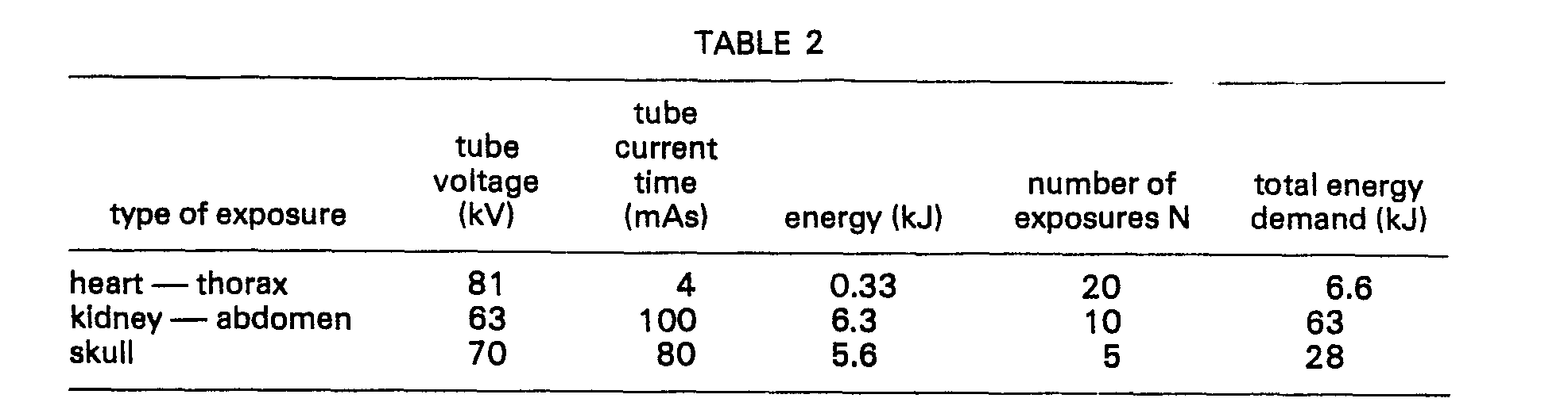
- The term "exposure series" means a sequence of subsequent discrete exposures which are completed one after another. The intervals between successive exposures is so short that the electric motor cannot increase significantly the speed of the
flywheel 4. Therefore the combined full energy for the exposure series must be provided by the mechanial energy obtained by a single slow-down process. - Table 3 shows data for the main types of individual exposures that require the highest energy.

- From Tables 1 to 3 it can be seen that the chosen value of moment of inertia is high enough to provide sufficient energy for carrying out all the kinds of exposures mentioned above at speeds which can be achieved easily in practice.
- The time required for the motor to reach the operational speed is invariably shorter than the time needed for adjusting the position of the patient between two exposures series or for setting a new patient in the proper position, and thus the equipment takes in the energy required for the next exposure or for the next exposure-series during the "idle" time between examinations.
- The processes that take place during the individual exposures or exposure-series will be described in connection with Figs. 20 and 21. The time scale of Fig. 20 is distorted, because for the sake of better understanding the exposure is shown longer than it would be in actual practice. Fig. 21 shows the mechanism of the regulation and the shape of the output signal during a single short exposure pulse, and compared to the scale applied in Fig. 20 its time scale is extended.
- It is assumed that immediately before the time to shown in Fig. 20, the
energy calculating unit 83 has an output signal corresponding to a preset minimum speed no and a reference signal corresponding to this speed no of about 3000 r.p.m. will appear at the output of the quantizingunit 82, which will be sent to the non-inverted input of thedifference circuit 80 of the speed regulating loop that controls the speed of the electric motor to reach the preset value of 3000 r.p.m. The operator sets the parameters of the exposure by means of thecontrol unit 100 in accordance with the diagnostic requirements. When, for example, the exposure-series is chosen for a skull examination as shown in the last line of Table 2, the tube voltage should be set to 70 kV, the tube current to 800 mA, the time of exposure to 0.1 sec and the number of exposures in the series should be set to 5. After setting the required values the operator presses the preparation push-button at the time to, and as a result thereof the inputs of theenergy calculating unit 83 will obtain in the form of analog signals the preset parameters of the exposure. Theunit 83 delivers an analog electric voltage signal at its output which controls the quantizingunit 82 and which is proportional to the full energy demand of 28 kJ of the exposure series (see Table 2). The discrete output signals of the quantizingunit 82 are selected in accordance with the discrete speed values given in Table 1, and for the energy demand of 28 kJ a reference signal corresponding to the speed of 7500 revolutions per minute will be sent from the output of the quantizingunit 82 to the non-inverted input of thedifference circuit 80. Thedifference circuit 80 controls thespeed regulating unit 79 by an analog signal which corresponds to the difference between the instantaneous speed of 3000 revolutions per minute and the required speed of 7000 revolutions per minute, and the electric motor will be driven to cause it to accelerate. The speed of theflywheel 4 increases continuously from the time to, as shown in Fig. 20. - When the preparation push-button is pressed, the automatic
tube protecting device 86 is informed on the preset parameters of the tube, and on the basis of this information it determines that with the preset tube voltage and current, with the energy of 5.6 kJ and exposure time of 0.1 sec belonging to a single exposure and with the total energy of 28 kJ for the whole series of five exposures, theX-ray tube 93 will operate within its normal dissipation range and sends an enable signal to thetube protection input 109 of thecontrol unit 100 at a time t1 (see Fig. 20b). - At a time t2 the speed of the electric motor reaches the preset value of 7500 revolutions per minute. In this case the value of the error signal will practically disappear at the output of the
difference circuit 80, and thecomparator unit 85 will send an enable signal to thespeed input 107 of the control unit 100 (see Fig. 20c). Thecontrol unit 100 is preferably designed so that when the speed enable signal appears a lamp will be switched on indicating that the exposure can be started. The exposure can be started in two steps. !n the first step a prestart signal is provided at time t3 which enables the operation of the auxiliary circuits 94 through the prestart output 106b. The auxiliary circuits 94 will switch on the heating of the filament of the cathode and the running up of the anode, and when theX-ray tube 93 reaches a state suitable for exposure at time t4 an enable signal shown in Fig. 20d is transmitted to theauxiliary circuit input 108 of thecontrol unit 100. Thereafter the operator can start the exposure. - The
control unit 100 is preferably fitted with an automatic timing device, which, following the occurrence of the speed enable signal, waits for a while e.g. for 30 seconds, to receive a prestart signal. If during this waiting time the prestart signal does not arrive, thecontrol unit 100 changes the level of the input signal of theenergy calculating unit 83, and as a result thereof the quantizingunit 82 will be set to the minimum speed setting i.e. 3000 revolutions per minute. Such control eliminates unnecessary running of the equipment. Similarly, after finishing a given program thecontrol unit 100 rotates the electric motor at a minimum speed of e.g. 3000 revolutions per minute for a certain time so that the next exposure can be started within a shorter period. This is the reason for the assumption made above that the electric motor is rotating with a speed of 3000 revolutions per minute before the prestart time to. It is obvious that if no prestart signal arrives within the preset time, e.g. within five minutes thecontrol unit 100 forbids the operation of the quantizingunit 82 across the enableinput 821, and the electric motor, not receiving any control voltage, will stop operating. - From time t4 onwards all the conditions required for starting the program of exposure are met, and the operator can start the program at time t5 by pressing the start of exposure button. At the first exposure a first pulse shown in Fig. 20f will appear at the
exposure output 101 of thecontrol unit 100, which pulse controls the enable input 92 of the pulse-width modulator 90, or in case of an alternative -design it controls thereference signal generator 118. In response to this enable signal the controlledswitch 91 starts operating and transmits the voltage of the controlled directcurrent voltage source 88 to thefield terminals generator unit 2 during the on-state of the controlling modulated pulse. Under the influence of the excitation an alternating voltage will be induced in theexciting machine 2A, which is rectified by therectifier 18 and sent to thefield magnet 6 of thegenerator 2B. A voltage is induced in the high voltage coils of thearmature 8 of thegenerator 2B and it is rectified by thehigh voltage rectifier 2D. The high voltage thus obtained will supply theX-ray tube 93. - As a result of the regulation the voltage and current parameters of the X-ray tube correspond to the values set by the
control unit 100. When the preset exposure time of 0.1 sec has elapsed, thecontrol unit 100 finishes supplying the exposure signal and thegenerator unit 2 gets de-excited. It can be observed in Fig. 20g that during the exposure the speed of the flywheel decreases rapidly and between two exposures it increases to an unsignificant extent, due to the switched on driving of the electric motor. - The
control unit 100 will generate all the exposure signals of the series in accordance with the program, and all the five exposures are completed sequentially. As to the total energy demand of the series, the selected speed of 7500 revolutions per minute will provide sufficient energy therefor so that the five exposures can be completed without the need for accelerating theflywheel 4. - It should be noted that the duration of the running-up of section T1, as indicated in Fig. 20, can vary from 1.5 to 2 minutes at the preset values, and with a driving motor of 600 W capacity the section T2 can vary from about 1 to 10 sec.
- During the section T3 of the exposure the field regulation circuits shown in Fig. 17 will provide the required parameters for the output signal. The essential time processes taking place during exposure are illustrated in Figs. 21 a to 21 e. Using the
excitation calculating unit 87 and relying on the preset values of the exposure, the energy demand of thegenerator unit 2 can be calculated in advance assuming a specified, approximately 20 to 30% space factor (duty cycle) in the way previously described. Bearing in mind the fact that at the beginning of the exposure the steepest possible pulse running-up shape should be provided, at the beginning section of the exposure, thegenerator unit 2 is over-excited by the differentiating elements in the regulatingunit 89. Fig. 21 e illustrates the signal shape of the pulses measured at thefield terminals field magnet 19 of the exciting machine. Fig. 21 b shows the high-voltage pulse applied to the X-ray tube 93 (the output voltage of the checking signal generating unit 11 is proportional to this pulse) and Fig. 21 a shows the speed of theflywheel 4. The time scale in Fig. 21 is given in milliseconds, and the front and rear pulse edges correspond to the shortest values that can be achieved. - The over-exciting during the initial section of the exposure can well be observed in Figs. 21c, d and e. After this section the space factor (duty cycle) of the exciting width-modulated pulse will suddenly decrease, and then will gradually increase under the influence of the proportional and integrating elements of the regulating
unit 89. In response to the decreases in speed theexcitation calculating unit 87 increases the output voltage of the controlled directcurrent voltage source 88, and therefore the amplitudes of the width-modulated pulses will increase as indicated in Fig. 21 e. - In Fig. 21 the dashed and dash-and-dot lines show the relations which exist when using enforced de-exciting circuits. Before describing such circuits the application of the apparatus according to the invention for fluoroscopy mode of operation will be discussed.
- According to an aspect of the invention it has been discovered that the sensed light intensity depends on the intensity of the transmitted illuminating rays. Owing to the persistance of vision of the human eye, if the fluoroscopic rays are emitted in a pulse-like manner with a relatively low space factor and with correspondingly increased intensity having such a high repetition frequency that they are sensed without flickering, then the sensed light intensity will be inversely proportional to the space factor of the pulses at every given radiation energy.
- Fig. 22 shows such fluoroscopic pulses having a peak intensity of i2 and an average intensity of i1. One pulse and the concomitant interval have together a time period ta, and the pulse itself has a duration tb. The energy of the pulse train having pulses with peak intensity of i2 and duration of tb will be given by the product ;2 . tb, and this is equal to the energy of a continuous fluoroscopic X-ray radiation with a peak intensity of i1 and a duration of ta. The main difference lies in the fact that in case of the pulsed fluoroscopy mode the sensed light intensity will be higher, the increase in sensed intensity corresponding to the ratio of i.ji1.
- In conventional fluoroscopy mode e.g. the following continuous parameters can be set: Tube voltage=100 kV, tube current=3 mA, power input=300 W. If, for example, 25 pulses are taken in each second, one pulse will last for 4 ms at a tube voltage of 100 kV and at a tube current of 30 mA and the average power consumption will be again 300 W. With such values a tenfold increase in the sensation of the light intensity will be obtained. The apparatus according to the invention provides a possibility for the continuous generation of pulses with such energy and duration values. This statement can be verified by the fact that the energy of such a 4 ms long pulse is only 0.012 kJ, which is significantly lower than the energy values given for various speeds in Table 1. The main difference between the fluoroscopy and radiography modes of operation is that in the former case between two subsequent exposures the electric motor can speed up the
flywheel 4 to reach again the initial speed, while in the latter case the electric motor can only slightly increase the speed between the exposures in an exposure series, as it has been explained above. This difference is caused by the fact that during fluoroscopy mode of operation, although the pulse power is 3 kW the average power consumption is only 300 W, and this consumption can be covered by the power of the driving electric motor. In case of an exposure series the total energy demand of each exposure in the series should be covered by the stored mechanical energy. In fluoroscopy mode of operation there can be a long-term continuous balance between the power demand and supply. - In case of the illustrated example the space factor of the pulses was 10. If a pulse length of 2 ms is chosen with a repetition frequency of 25 pulses per seconds i.e. with a period time of 40 ms, the light intensity will increase twenty-fold, and in case of 1 ms long pulses it will increase fortyfold having a pulse power of 12 kW.
- Since in the fluoroscopy mode of operation only a small amount of energy is taken out from the
flywheel 4, it is sufficient for the power balance if the flywheel is operated with a lower speed. In this mode of operation thecontrol unit 100 controls the higher priority input of the quantizingunit 82 through the line 102b and in response to such a control the quantizingunit 82 independent of the calculated energy, generates a speed reference signal that corresponds to the lowest discrete speed. If during fluoroscopy a special-purpose radiography exposure is to be taken, then the quantizingunit 82 adjusts the speed according to the energy demand of this exposure. - Fig. 21 shows that the steepness of the front-edge of the exposure pulse can be increased to the required extent by appropriate over-excitation. The shortest running-up time obtained this way can be approximately 0.1 to 0.2 msec.
- When the excitation has finished, the self-de-excitation occur at a slower rate due to the remanence of the field magnets and the time constant of the winding, and in order to provide a definite short rear edge, the de-excitation process should be enforcedly accelerated. In the case of the exciting machine this is an easier task. For accelerating the de-excitation of the exciting machine it is possible, for example, to couple an excitation of opposite polarity to the
field magnet 19 of the exciting machine through thefield terminals field magnet 19 of the exciting machine through an appropriate switching transistor. Such a de-exciting pulse is represented by the last negative polarity spike in the pulse train shown in diagram of Fig. 21. - Although there are several possibilities for achieving enforced de-excitation of the
field magnet 6 of thegenerator 28, some examples of de-exciting circuits will be discussed in connection with Figs. 23 and 24, which are preferred because of their simplicity. - In Fig. 23 the winding of the
armature 17 of the exciting machine is shown with therectifier 18 which rotates together with it. Between thefield magnet 6 and therectifier 18 there is atransistor 120, the base of which is connected to the common cathode of the diodes of the rectifier through aresistor 121. Thefield magnet 6 is connected in parallel with acapacitor 122. - The
transistor 120 is controlled in the forward direction by the output direct current voltage of therectifier 18, so that during excitation thefield magnet 6 is energised through thetransistor 120 in the way described above. When at the end of the exposure signal the excitation is finished, the voltage of thearmature 17 of the exciting machine will drop to zero and an induced voltage of opposite polarity will appear at the coil of thefield magnet 6, and this voltage attempts to maintain the current at the expense of the stored magnetic energy. In this case, however, the forward control of thetransistor 120 has already ceased, so that thetransistor 120 will break the circuit of thefield magnet 6, resulting in a fast de-excitation. Since the circuit elements shown in Fig. 23 i.e. thearmature 17 of the exciting machine, therectifier 18 and thefield magnet 6 are all built in and rotate together with theflywheel 4, the elements providing the fast de-excitation should also be affixed to theflywheel 4. The effect of the de-exciting circuit shown in Fig. 23 is illustrated in Fig. 21 by a curve drawn with a dashed line. - Fig. 24 shows an example of an active de-exciting circuit connection that also comprises the
transistor 120 and theresistor 121 illustrated in Fig. 23, but here thefield magnet 6 is connected to a circuit providing an excitation of reversed direction. Apart from therectifier 18 thearmature 17 of the exciting machine is connected additionally to asecond rectifier 123 generating direct current voltage of opposite polarity, and thisrectifier 123 is connected to one of the plates of anenergy storing capacitor 124. The other plate of thecapacitor 124 is connected to that end terminal of thefield magnet 6 which is coupled to the collector of thetransistor 120. Between the first plate of theenergy storing capacitor 124 and the upper end terminal of thefield magnet 6 there is a pass-throughtransistor 125 which is by-passed by a protectingdiode 126. A controllingtransistor 127 and itscollector resistor 128 are connected between the plates of the energy storing capacitor. The base of thetransistor 125 is connected to the collector of a controllingtransistor 127 and the base of the controllingtransistor 127 is connected through aresistor 129 and aparallel capacitor 130 to the collector of the pass-throughtransistor 125. - The de-exciting circuit shown in Fig. 24 operates as follows. The
rectifier 123 charges theenergy storing capacitor 124 with a voltage of such a polarity (in this case positive) that drives a current through thefield magnet 6 which flows oppositely to the normal exciting current when the pass-throughtransistor 125 is open. When thearmature 17 of the exciting machine generates voltage, the -transistor 125 is kept in an off state by the controllingtransistor 127 being in a conducting state, and at the upper terminal of thefield magnet 6 there is a negative voltage coming from therectifier 18. When the excitation is finished the voltage of thearmature 17 of the exciting machine returns to zero and the controllingtransistor 127 is closed and thetransistor 125 opens. Thecapacitor 130 accelerates the ciosing of the controllingtransistor 127. From the positively charged energy storing capacitor through the transistor 125 a current of opposite direction will flow to thefield magnet 6, resulting in fast de-excitation of the generator. Similar, to the circuit illustrated in Fig. 23 the elements of the circuit shown in Fig. 24 are built in and rotate with theflywheel 4. The curve drawn in a dotted and dashed line in Fig. 21 illustrates the effect of the circuit shown in Fig. 24. - It should be clear from the above explanation that by accelerated de-excitation the rear edge of the output pulse can be steeper, and the off-going time can be adjusted to between about 0.2 and 0.5 msec. For the construction described hereinabove as an example of the apparatus according to the invention, the duration of the shortest pulse which can be generated is approximately 0.6-0.8 msec.
- Obviously constructions can also be used for the enforced de-excitation other than those shown in Figs. 23 and 24. According to an alternative embodiment the exciting machine may have in addition to the armature 17 a separate de-exciting armature winding which can be connected to the
field magnet 6 through a rectifier and a switching transistor having operating principles similar to those oftransistor 120 indicated in Fig. 23. If a separate field magnet energised only for the duration of the de-excitation is associated with this separate winding of the exciting machine, the generated voltage will induce a current of opposite direction in thefield magnet 6, resulting in the fast ending of the voltage. - In another alternative embodiment sections of a permanent magnet can be built in the pole core of the
field magnet 6, or a ring of poles with permanent magnets can be arranged adjacent thereto, so that magnetic fields of these poles can compensate the remanence of the pole core. As a result of this compensation the remaining magnetic field of thefield magnet 6 cannot generate a voltage when excitation has finished. - Another possibility for the fast killing of the remaining voltage is to provide short-circuited windings on the armature of the generator. The turns of this winding should be short-circuited by a separate control unit only for the duration of the complete de-energisation. For this purpose switching circuits controlled by the rear edges of the exposure pulses can be used.
- In connection with the embodiments illustrated as example in Figs. 1 to 24 it is to be understood that the apparatus according to the invention fulfills its basic task i.e. it provides power supply for pulse-like loads with a high power capacity, requires a low power source and as an additional feature it renders possible a sophisticated form of control for the X-ray equipment. In conventional X-ray equipment short exposures are set by biassed magnetic multiphase switches constructed for the peak power of the X-ray equipment. Instead of using the conventional switching unit and the associated automatic control device, the control tasks of the X-ray equipment can be solved according to the invention at a power level which is three to four order of magnitude less than in conventional controls, resulting in lower costs and with smaller dimensions.
- Each parameter of the output pulses can be set to specified values, so that the apparatus according to the invention can provide not only high pulse power but also ensure precisely specified voltage and current behaviour during exposure.
- As a result of the increase in the sensation of light intensity achieved by pulsed fluoroscopy, optical darkening of the fluoroscopy room becomes an unnecessary requirement in case of normal radiation doses. Alternative traditional light intensity can be obtained with significantly smaller irradiation doses. The former advantage improves the working conditions for radiologists and facilitates the picture evaluation, while the latter decreases the dose.
- An apparatus according to the invention which can provide the exposure parameters described in the examples, can be manufactured with a diameter of 0.3 metre, a height of 0.7 metre and with a total weight of approximately 90 kiloponds. The approximate dimensions and weight of the control unit associated therewith are 0.2 mxO.3 mx0.4 m and 10 kps, respectively.
- The high-voltage transformer unit of a traditional X-ray equipment with similar power capacity itself weighs approximately 400 kps, with dimensions of 0.5x0.7x1.2 m, and the dimensions of the control system with the high power switches are 0.5x0.9x1 m, and their weight is 200 kps. Furthermore a conventional control unit is also required for setting the desired exposure values.
- For the purpose of comparison it should also be noted that for the operation of a traditional X-ray equipment a three-phase electric network of 100 kW power capacity is required with approximately 0.05 ohms loop resistance in all the three phases, while in the case of an apparatus according to the invention operating with the same power, only a one-phase electric network is required which can supply a power of 600 to 800 W and its network resistance can be as high as a few ohms.
- The apparatus according to the invention is suitable for supplying not only X-ray apparatuses but it can be used in all applications where the load requires a pulse-like high power supply with a predetermined voltage. In such cases both the level and the time function of the output voltage can be kept at the desired or preset values by means of the control circuits. The driving motor of the flywheel should provide only the average power consumption of the load. The apparatus according to the invention can be used for supplying loads operating with high pulse power, such as, for example, pulse- laser equipment, microwave pulse-generators (radars) linear accelerators and betatrons.
- Within the field of radiology the apparatus according to the invention can be suitable for providing a simple controlled primary side supply for the high voltage circuit of conventional X-ray equipment.
Claims (26)
Priority Applications (1)
| Application Number | Priority Date | Filing Date | Title |
|---|---|---|---|
| DE7979300750T DE2965602D1 (en) | 1979-05-02 | 1979-05-02 | Apparatus for supplying high power electric loads operated in a pulse-like manner, and method for carrying out fluoroscopy |
Applications Claiming Priority (1)
| Application Number | Priority Date | Filing Date | Title |
|---|---|---|---|
| US06/029,352 US4355276A (en) | 1979-04-11 | 1979-04-11 | Apparatus for supplying high power electric loads operated in a pulse-like manner, especially for X-ray equipment |
Publications (2)
| Publication Number | Publication Date |
|---|---|
| EP0018455A1 EP0018455A1 (en) | 1980-11-12 |
| EP0018455B1 true EP0018455B1 (en) | 1983-06-08 |
Family
ID=21848602
Family Applications (1)
| Application Number | Title | Priority Date | Filing Date |
|---|---|---|---|
| EP79300750A Expired EP0018455B1 (en) | 1979-04-11 | 1979-05-02 | Apparatus for supplying high power electric loads operated in a pulse-like manner, and method for carrying out fluoroscopy |
Country Status (4)
| Country | Link |
|---|---|
| US (1) | US4355276A (en) |
| EP (1) | EP0018455B1 (en) |
| AT (1) | ATE3742T1 (en) |
| AU (1) | AU530228B2 (en) |
Families Citing this family (31)
| Publication number | Priority date | Publication date | Assignee | Title |
|---|---|---|---|---|
| EP0090034A4 (en) * | 1981-09-30 | 1984-02-07 | Oscar A Lin | Pulse electro-magnets rotation energy accumulation method and system. |
| US4498015A (en) * | 1982-12-13 | 1985-02-05 | Gottfried Mario H | Flywheel device for a moving vehicle |
| US4540930A (en) * | 1983-09-12 | 1985-09-10 | Wisconsin Alumni Research Foundation | Plywheel-powered mobile X-ray apparatus |
| US4642535A (en) * | 1983-12-29 | 1987-02-10 | Sundstrand Corporation | Electromagnetic energy storage and supply system |
| US4841217A (en) * | 1987-12-14 | 1989-06-20 | The University Of Texas System | Pulsed generator incorporating output waveform flexibility and a pulsed transformer |
| JPH0559007U (en) * | 1991-07-01 | 1993-08-03 | 茂 平松 | Rotational force increasing device |
| US5212437A (en) * | 1991-08-02 | 1993-05-18 | Picker International, Inc. | High speed starter operations monitor |
| US5555120A (en) * | 1994-11-10 | 1996-09-10 | Telymonde; Timothy D. | Cordless control system for an x-ray apparatus |
| DE4444361A1 (en) * | 1994-12-14 | 1996-06-20 | Philips Patentverwaltung | Process for monitoring the speed of an induction motor |
| US5614777A (en) * | 1995-02-06 | 1997-03-25 | U.S. Flywheel Systems | Flywheel based energy storage system |
| AU6026096A (en) * | 1995-06-06 | 1996-12-24 | Magnetic Bearing Technologies, Inc. | Pulsed power rotary amplifier |
| US5770909A (en) * | 1996-12-13 | 1998-06-23 | Rosen Motors, L.P. | Wound rotor synchronous motor-generator and field control system therefor |
| BE1013177A3 (en) * | 1999-12-13 | 2001-10-02 | Ind Control Machines S A | Feeder for thread of x ray tube |
| US6195272B1 (en) | 2000-03-16 | 2001-02-27 | Joseph E. Pascente | Pulsed high voltage power supply radiography system having a one to one correspondence between low voltage input pulses and high voltage output pulses |
| US6707276B2 (en) * | 2000-06-26 | 2004-03-16 | Denso Corporation | Voltage regulator of AC generator having circuit for detecting voltage induced in field coil |
| US7081696B2 (en) | 2004-08-12 | 2006-07-25 | Exro Technologies Inc. | Polyphasic multi-coil generator |
| US7230344B2 (en) * | 2004-09-17 | 2007-06-12 | Rockwell Automation Technologies, Inc. | Apparatus and method for transient and uninterruptible power |
| KR101484980B1 (en) | 2006-06-08 | 2015-01-28 | 엑스로 테크놀러지 아이엔씨. | Multiphase multiple coil generator |
| CN101502185A (en) * | 2006-08-10 | 2009-08-05 | 皇家飞利浦电子股份有限公司 | Fly wheel electrode of an x-ray tube |
| US9126487B2 (en) | 2013-03-15 | 2015-09-08 | Arx Pax, LLC | Hoverboard which generates magnetic lift to carry a person |
| US9352665B2 (en) | 2013-03-15 | 2016-05-31 | Arx Pax Labs, Inc. | Magnetically lifted vehicles using hover engines |
| US9148077B2 (en) * | 2013-03-15 | 2015-09-29 | Arx Pax, LLC | Magnetic levitation of a stationary or moving object |
| US9744878B2 (en) | 2013-03-15 | 2017-08-29 | Arx Pax Labs, Inc. | Magnetically lifted vehicles using hover engines |
| US9263974B1 (en) | 2013-03-15 | 2016-02-16 | Arx Pax, LLC | Hover engine for a hoverboard which generates magnetic lift to carry a person |
| KR20170015881A (en) | 2014-04-08 | 2017-02-10 | 아르스 팍스 랩스, 인크. | Hoverboard |
| EP3586431A4 (en) | 2017-05-23 | 2020-11-11 | DPM Technologies Inc. | Variable coil configuration system control, apparatus and method |
| WO2020047663A1 (en) | 2018-09-05 | 2020-03-12 | Dpm Technologies Inc. | Systems and methods for intelligent energy storage and provisioning using an energy storage control system |
| US11722026B2 (en) | 2019-04-23 | 2023-08-08 | Dpm Technologies Inc. | Fault tolerant rotating electric machine |
| CN110057473B (en) * | 2019-04-30 | 2021-03-26 | 南京信息职业技术学院 | Excitation circuit of single-coil vibrating wire sensor and measuring circuit thereof |
| US11897362B2 (en) | 2021-05-04 | 2024-02-13 | Exro Technologies Inc. | Systems and methods for individual control of a plurality of controllable units of battery cells |
| JP2024518405A (en) | 2021-05-13 | 2024-05-01 | エクスロ テクノロジーズ インク. | Method and apparatus for driving coils of a polyphase electric machine - Patents.com |
Family Cites Families (17)
| Publication number | Priority date | Publication date | Assignee | Title |
|---|---|---|---|---|
| US1456955A (en) * | 1921-02-26 | 1923-05-29 | Westinghouse Electric & Mfg Co | Means for obtaining high momentary current |
| US2301424A (en) * | 1936-05-19 | 1942-11-10 | List Heinrich | Apparatus for generating extremely large short-duration energy impulses |
| GB702462A (en) * | 1950-11-28 | 1954-01-20 | Philips Electrical Ind Ltd | Improvements in and relating to x-ray apparatus |
| US2962594A (en) * | 1956-09-14 | 1960-11-29 | Westinghouse Electric Corp | X-ray apparatus |
| DE1078244B (en) * | 1958-04-18 | 1960-03-24 | Siemens Reiniger Werke Ag | X-ray diagnostic apparatus with initial loading |
| DE1149099B (en) * | 1958-10-28 | 1963-05-22 | Siemens Ag | Exciter arrangement for electrical machines |
| US3193713A (en) * | 1960-10-06 | 1965-07-06 | Gen Motors Corp | Inductor alternator |
| CH459774A (en) * | 1965-09-16 | 1968-07-15 | Oerlikon Maschf | Vehicle with rotational energy storage, process for its operation and process for its production |
| FR1475945A (en) * | 1966-02-25 | 1967-04-07 | Brissonneau & Lotz | Electro-mechanical process and assembly for the accumulation of energy and its return at very high power |
| FR1502641A (en) * | 1966-03-10 | 1967-11-24 | Unelec | Rotary electric pump with radial air gap |
| US3569791A (en) * | 1969-10-22 | 1971-03-09 | Atomic Energy Commission | Remanent-free pulsing magnets |
| FR2071510A5 (en) * | 1969-12-31 | 1971-09-17 | Edf | |
| JPS5233522Y2 (en) * | 1971-08-14 | 1977-07-30 | ||
| DE2631469C2 (en) * | 1975-08-22 | 1986-03-06 | Sundstrand Corp., Rockford, Ill. | Rotating exciter arrangement for a synchronous machine |
| BE834293A (en) * | 1975-10-08 | 1976-04-08 | Acec | DOUBLE DYNAMOELECTRIC MACHINE |
| US4182967A (en) * | 1977-05-23 | 1980-01-08 | Jordan Robert D | Energy storage system |
| US4200831A (en) * | 1978-08-03 | 1980-04-29 | The United States Of America As Represented By The United States Department Of Energy | Compensated pulsed alternator |
-
1979
- 1979-04-11 US US06/029,352 patent/US4355276A/en not_active Expired - Lifetime
- 1979-05-02 AT AT79300750T patent/ATE3742T1/en not_active IP Right Cessation
- 1979-05-02 EP EP79300750A patent/EP0018455B1/en not_active Expired
- 1979-05-08 AU AU46847/79A patent/AU530228B2/en not_active Ceased
Also Published As
| Publication number | Publication date |
|---|---|
| AU4684779A (en) | 1980-11-13 |
| EP0018455A1 (en) | 1980-11-12 |
| US4355276A (en) | 1982-10-19 |
| ATE3742T1 (en) | 1983-06-15 |
| AU530228B2 (en) | 1983-07-07 |
Similar Documents
| Publication | Publication Date | Title |
|---|---|---|
| US4355276A (en) | Apparatus for supplying high power electric loads operated in a pulse-like manner, especially for X-ray equipment | |
| US6380655B1 (en) | Variable-speed electromechanical energy converter | |
| CA1177888A (en) | Greatly prolonged period non-interruptible power supply system | |
| US5955809A (en) | Permanent magnet generator with auxiliary winding | |
| CA1214569A (en) | Flywheel powered mobile x-ray apparatus | |
| US6891302B1 (en) | Light-weight high-power electrical machine | |
| EP2052591A2 (en) | Fly wheel electrode of an x-ray tube | |
| EP2538546A2 (en) | Electrical system architecture and electrical power generation system | |
| AU2001230125B2 (en) | Synchronous generator | |
| WO2024088425A1 (en) | Wireless power transmission apparatus and imaging device comprising same | |
| DE3825349A1 (en) | Portable, variable radio-frequency generator | |
| EP0011458A1 (en) | Computerized tomographic apparatus with a continuously rotating source of X-rays | |
| KR101417509B1 (en) | Synchronous generator system haing dual rotor | |
| CA1133145A (en) | Apparatus for supplying high power electric loads operated in a pulse-like manner, especially for x-ray equipments | |
| US4024455A (en) | Rotary inverters for converting D.C. to A.C. | |
| US5060252A (en) | Generator for operating a rotating anode x-ray tube | |
| US20140361807A1 (en) | Test apparatus and method for testing a first and/or a second electrical machine | |
| US2717315A (en) | X-ray apparatus | |
| HU180107B (en) | Equipment for supplying high power electric consumers operated in pluse like service,in particular x-ray apparatuses with current | |
| PL123467B1 (en) | Apparatus for supplying pulse operating high power energy receivers | |
| KR20140110955A (en) | Generator of a gearless wind turbine | |
| US5265146A (en) | X-ray tube rotor controller using the main high voltage inverters for acceleration and speed maintenance | |
| CN113328594A (en) | Alternating-current magnetic field control multiphase flywheel pulse generator system | |
| KR101380024B1 (en) | System for controlling super conduction generator | |
| RU2249288C2 (en) | Mechanical electrical-energy storage |
Legal Events
| Date | Code | Title | Description |
|---|---|---|---|
| PUAI | Public reference made under article 153(3) epc to a published international application that has entered the european phase |
Free format text: ORIGINAL CODE: 0009012 |
|
| AK | Designated contracting states |
Designated state(s): AT BE CH DE FR GB IT NL SE |
|
| 17P | Request for examination filed |
Effective date: 19801006 |
|
| ITF | It: translation for a ep patent filed | ||
| GRAA | (expected) grant |
Free format text: ORIGINAL CODE: 0009210 |
|
| AK | Designated contracting states |
Designated state(s): AT BE CH DE FR GB IT NL SE |
|
| REF | Corresponds to: |
Ref document number: 3742 Country of ref document: AT Date of ref document: 19830615 Kind code of ref document: T |
|
| REF | Corresponds to: |
Ref document number: 2965602 Country of ref document: DE Date of ref document: 19830714 |
|
| ET | Fr: translation filed | ||
| PLBE | No opposition filed within time limit |
Free format text: ORIGINAL CODE: 0009261 |
|
| STAA | Information on the status of an ep patent application or granted ep patent |
Free format text: STATUS: NO OPPOSITION FILED WITHIN TIME LIMIT |
|
| 26N | No opposition filed | ||
| ITTA | It: last paid annual fee | ||
| PGFP | Annual fee paid to national office [announced via postgrant information from national office to epo] |
Ref country code: NL Payment date: 19900531 Year of fee payment: 12 |
|
| PGFP | Annual fee paid to national office [announced via postgrant information from national office to epo] |
Ref country code: GB Payment date: 19900711 Year of fee payment: 12 |
|
| PGFP | Annual fee paid to national office [announced via postgrant information from national office to epo] |
Ref country code: AT Payment date: 19900713 Year of fee payment: 12 |
|
| PGFP | Annual fee paid to national office [announced via postgrant information from national office to epo] |
Ref country code: FR Payment date: 19900717 Year of fee payment: 12 |
|
| PGFP | Annual fee paid to national office [announced via postgrant information from national office to epo] |
Ref country code: SE Payment date: 19900718 Year of fee payment: 12 |
|
| PGFP | Annual fee paid to national office [announced via postgrant information from national office to epo] |
Ref country code: CH Payment date: 19900726 Year of fee payment: 12 |
|
| PGFP | Annual fee paid to national office [announced via postgrant information from national office to epo] |
Ref country code: DE Payment date: 19900730 Year of fee payment: 12 |
|
| PGFP | Annual fee paid to national office [announced via postgrant information from national office to epo] |
Ref country code: BE Payment date: 19900808 Year of fee payment: 12 |
|
| PG25 | Lapsed in a contracting state [announced via postgrant information from national office to epo] |
Ref country code: GB Effective date: 19910502 Ref country code: AT Effective date: 19910502 |
|
| PG25 | Lapsed in a contracting state [announced via postgrant information from national office to epo] |
Ref country code: SE Effective date: 19910503 |
|
| PG25 | Lapsed in a contracting state [announced via postgrant information from national office to epo] |
Ref country code: CH Effective date: 19910531 Ref country code: BE Effective date: 19910531 |
|
| BERE | Be: lapsed |
Owner name: MEDICOR MUVEK Effective date: 19910531 |
|
| PG25 | Lapsed in a contracting state [announced via postgrant information from national office to epo] |
Ref country code: NL Effective date: 19911201 |
|
| GBPC | Gb: european patent ceased through non-payment of renewal fee | ||
| NLV4 | Nl: lapsed or anulled due to non-payment of the annual fee | ||
| PG25 | Lapsed in a contracting state [announced via postgrant information from national office to epo] |
Ref country code: FR Effective date: 19920131 |
|
| REG | Reference to a national code |
Ref country code: CH Ref legal event code: PL |
|
| PG25 | Lapsed in a contracting state [announced via postgrant information from national office to epo] |
Ref country code: DE Effective date: 19920303 |
|
| REG | Reference to a national code |
Ref country code: FR Ref legal event code: ST |
|
| EUG | Se: european patent has lapsed |
Ref document number: 79300750.1 Effective date: 19911209 |