EP0018300B1 - Tuyère de propulseur à divergent déployable - Google Patents
Tuyère de propulseur à divergent déployable Download PDFInfo
- Publication number
- EP0018300B1 EP0018300B1 EP80400548A EP80400548A EP0018300B1 EP 0018300 B1 EP0018300 B1 EP 0018300B1 EP 80400548 A EP80400548 A EP 80400548A EP 80400548 A EP80400548 A EP 80400548A EP 0018300 B1 EP0018300 B1 EP 0018300B1
- Authority
- EP
- European Patent Office
- Prior art keywords
- layer
- flexible
- sub
- rigid
- rings
- Prior art date
- Legal status (The legal status is an assumption and is not a legal conclusion. Google has not performed a legal analysis and makes no representation as to the accuracy of the status listed.)
- Expired
Links
- 239000002131 composite material Substances 0.000 claims description 19
- 239000004753 textile Substances 0.000 claims description 11
- 239000000835 fiber Substances 0.000 claims description 10
- 229920001971 elastomer Polymers 0.000 claims description 8
- 239000000806 elastomer Substances 0.000 claims description 8
- 239000004744 fabric Substances 0.000 claims description 6
- 238000005470 impregnation Methods 0.000 claims description 5
- 239000011347 resin Substances 0.000 claims description 5
- 229920005989 resin Polymers 0.000 claims description 5
- 239000012774 insulation material Substances 0.000 claims description 4
- 238000004804 winding Methods 0.000 claims description 4
- 239000000805 composite resin Substances 0.000 claims description 3
- VYPSYNLAJGMNEJ-UHFFFAOYSA-N Silicium dioxide Chemical compound O=[Si]=O VYPSYNLAJGMNEJ-UHFFFAOYSA-N 0.000 description 14
- OKTJSMMVPCPJKN-UHFFFAOYSA-N Carbon Chemical compound [C] OKTJSMMVPCPJKN-UHFFFAOYSA-N 0.000 description 7
- 229910052799 carbon Inorganic materials 0.000 description 7
- 239000000377 silicon dioxide Substances 0.000 description 7
- 238000004026 adhesive bonding Methods 0.000 description 3
- 238000011084 recovery Methods 0.000 description 3
- 239000004760 aramid Substances 0.000 description 2
- 229920003235 aromatic polyamide Polymers 0.000 description 2
- 239000011248 coating agent Substances 0.000 description 2
- 238000000576 coating method Methods 0.000 description 2
- 239000011521 glass Substances 0.000 description 2
- 238000009413 insulation Methods 0.000 description 2
- 238000004519 manufacturing process Methods 0.000 description 2
- 239000000463 material Substances 0.000 description 2
- 238000003860 storage Methods 0.000 description 2
- KXGFMDJXCMQABM-UHFFFAOYSA-N 2-methoxy-6-methylphenol Chemical compound [CH]OC1=CC=CC([CH])=C1O KXGFMDJXCMQABM-UHFFFAOYSA-N 0.000 description 1
- 229920000049 Carbon (fiber) Polymers 0.000 description 1
- 238000002679 ablation Methods 0.000 description 1
- 239000004917 carbon fiber Substances 0.000 description 1
- 239000000470 constituent Substances 0.000 description 1
- 238000011065 in-situ storage Methods 0.000 description 1
- 239000007769 metal material Substances 0.000 description 1
- 239000005011 phenolic resin Substances 0.000 description 1
- 229920001568 phenolic resin Polymers 0.000 description 1
- 239000003380 propellant Substances 0.000 description 1
- 239000012209 synthetic fiber Substances 0.000 description 1
- 229920002994 synthetic fiber Polymers 0.000 description 1
- 230000008646 thermal stress Effects 0.000 description 1
- 210000003462 vein Anatomy 0.000 description 1
Images

Classifications
-
- F—MECHANICAL ENGINEERING; LIGHTING; HEATING; WEAPONS; BLASTING
- F02—COMBUSTION ENGINES; HOT-GAS OR COMBUSTION-PRODUCT ENGINE PLANTS
- F02K—JET-PROPULSION PLANTS
- F02K9/00—Rocket-engine plants, i.e. plants carrying both fuel and oxidant therefor; Control thereof
- F02K9/97—Rocket nozzles
- F02K9/976—Deployable nozzles
-
- F—MECHANICAL ENGINEERING; LIGHTING; HEATING; WEAPONS; BLASTING
- F05—INDEXING SCHEMES RELATING TO ENGINES OR PUMPS IN VARIOUS SUBCLASSES OF CLASSES F01-F04
- F05D—INDEXING SCHEME FOR ASPECTS RELATING TO NON-POSITIVE-DISPLACEMENT MACHINES OR ENGINES, GAS-TURBINES OR JET-PROPULSION PLANTS
- F05D2250/00—Geometry
- F05D2250/30—Arrangement of components
- F05D2250/32—Arrangement of components according to their shape
- F05D2250/324—Arrangement of components according to their shape divergent
Definitions
- French patent application No. 78/03090 (published under No. 2 422 831) describes and claims a propellant nozzle comprising a deployable divergent formed by a succession of rigid rings connected to each other and to the nozzle body by rings flexible. These comprise a flexible annular support constituted for example by an elastomer sheet possibly reinforced with synthetic fibers, and a fur coating the internal face of said support. This fur is formed of textile structures offering great freedom of orientation.
- each of the flexible rings is lined with an undercoat attached to the elastomer sheet.
- Textile structures, such as threads, fur, are attached to this undercoat, which may be composed of a skin made of carbon fibers or silica, or of two superimposed skins.
- the rigid rings consist of a layer of thermal insulation material such as a composite of carbon or silica fibers and phenolic resin, optionally coated on the outside with a metallic envelope.
- the flexible ring-rigid ring (or - nozzle body) connections are provided by overflowing, on a small part of an adjacent rigid ring, of the sublayer and of the flexible support.
- the present invention relates to a deployable diverging nozzle having the general structure described in the aforementioned patent application.
- the aforementioned flexible support and underlay extend over the entire length of the divergent and thus constitute a flexible conical envelope extending continuously in the deformable zones and in the non-deformable zones of the diverging part, while the rigid rings corresponding to these latter zones are produced by means of annular layers of rigid composite thermal insulation material.
- Such an arrangement simplifies the manufacture and assembly of the constituent elements of the deployable divergent, all the flexible rings being produced in one piece. It contributes to improving the mechanical strength of the assembly due to the continuity of the sub-layer which constitutes the resistant part of the flexible envelope. It makes it possible to keep the same vein material all along the nozzle and thus to avoid possible variations in profile due to a different resistance to ablation between the “flexible” material and the composite materials of the diverging part of the nozzle.
- the aforementioned fur can also extend over the entire length of the divergent, possibly offering an evolving thickness, while the composite material forming the rigid rings can be located between the underlay and the flexible support, the latter completely covering the external face of the divergent by bonding or impregnation on the one hand on the undercoat in the deformable areas and on the other hand on the rigid layer of composite material in the non-deformable areas.
- the composite material forming the rigid rings may, on the contrary, be situated outside the flexible support, the latter directly covering the entire external face of the underlay.
- Each annular layer of composite material forming a rigid ring is then preferably deposited on the flexible support by rewinding or by draping fibers or textile wicks impregnated with polymerizable resin.
- the fur does not extend beyond the deformable zones of the divergent section and gives way, in the non-deformable zones, to an annular layer of composite material forming each rigid ring, secured to the internal face of the sub- layer, while the flexible support directly lines the entire outer face of the underlay.
- the protruding parts of the aforementioned sublayer and flexible support on the nozzle body can advantageously be joined thereto by a rewinding of a fiber / resin composite.
- Figure 1 shows an axial half-section of a divergent according to the present invention, in the storage position.
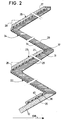
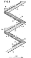
- FIGS. 2 and 3 show in the same way two alternative embodiments of a divergent according to the present invention.
- FIG. 1 there is shown a diverging nozzle according to the invention, comprising, following a rigid nozzle body 10, a succession of alternately flexible and rigid rings, with general references 22 to 25.
- the direction the axis of the nozzle is indicated by the arrow 138.
- the flexible and rigid rings offer a common part constituted by a flexible underlayer 31 extending over the entire length of the divergent, here shown in the folded storage position.
- This sub-layer is composed of a skin or two superimposed skins made of fabric or knitted of refractory fibers (carbon or silica for example).
- On the entire inner face of this underlayer 31 is hung a carpet or fur 29 of textile structures formed and arranged according to the teachings of French patent application No. 78/03090 published under No.
- these textile structures are refractory structures for example based on carbon, silica, carbon or silica with impregnation of resin, etc.
- this fur has, as shown, an evolving thickness all along its profile, insofar as the thermal stresses are less significant towards the end zone.
- an annular layer 27 On the external face of the underlayer 31 is added, in the non-deformable zones of the rigid rings, an annular layer 27 much thicker than the underlayer 31, made of composite material of thermal insulation.
- This layer 27 is formed of fibers or textile wicks (fibers or wicks of aromatic polyamides, glass, carbon, silica, etc.) impregnated with resin and subsequently polymerized.
- An elastomeric sheet 34 forming a flexible support then completely covers the external face of the divergent by bonding or impregnation both on the underlayer 31 in the deformable zones to form the flexible rings 22 and 24, and on the rigid layer 27 in the non-deformable zones to constitute the rigid rings 23 and 25.
- the elastomer sheet 34 is separated from the underlayer 31 in order to allow its elongation during the deployment movements of the nozzle.
- Each rigid ring 23, 25 has at its front part a heel 28 for the recovery of forces resulting from the attachment of actuating cylinders for the deployment of the nozzle, not shown.
- the flexible annular sublayer 31 also extends, as in the embodiment of Figure 1, over the entire length of the divergent. It is also coated on its entire internal face with a fur 29 of textile structures with great freedom of orientation.
- An elastomer sheet 34 forming a flexible support is applied to the external face of the underlayer 31 to form an integral part thereof. It can be simply superimposed in the deformable zones to constitute the flexible rings 22, 24. It is linked by any suitable means to the underlayer 31 in the non-deformable zones. These are obtained by externally coating the flexible support 34 with a layer 27 of composite thermal insulation material.
- This layer is formed by draping or in situ winding of fibers or textile wicks (fibers or wicks of aromatic polyamides, glass, carbon, silica, etc.) impregnated with subsequently polymerized resin, to form the rigid rings 23 , 25.
- Obtaining force recovery points or heels 28 on the latter (attachment of the jacks for example) is then done in a conventional manner by having inserts during winding, for example.
- the parts 35, 36 of the sub-layer 31 and of the elastomer sheet 34 project over the nozzle body 10 to which they are joined by a rewinding 47 of a fiber / resin composite.
- FIG 3 there is shown a second alternative embodiment of a deployable divergent comprising a succession of rigid rings and flexible rings.
- the underlayer 31 is made of fabric or carbon knit in a single piece the size of the deployable divergent.
- the external face of this sub-layer is completely coated, by bonding or impregnation, with an elastomer sheet 34 constituting a flexible support.
- a fur 29 of textile structures is hung on the internal wall of the underlayer 31 and forms with the support the flexible rings 22 and 24.
- the rigid rings 23, 25 are obtained by means of a thick layer 27 made of thermal insulation composite material and secured to the internal face of the underlayer 31 either by gluing and / or stitching, or by mechanical connection.
- a force recovery piece or heel 28 made of composite or metallic material, while the projecting parts 35, 36 are fixed to the nozzle body 10 by means of an attached flange 47 composite or metallic.
Landscapes
- Engineering & Computer Science (AREA)
- Chemical & Material Sciences (AREA)
- Combustion & Propulsion (AREA)
- Mechanical Engineering (AREA)
- General Engineering & Computer Science (AREA)
- Laminated Bodies (AREA)
- Rigid Pipes And Flexible Pipes (AREA)
Applications Claiming Priority (2)
| Application Number | Priority Date | Filing Date | Title |
|---|---|---|---|
| FR7910366 | 1979-04-24 | ||
| FR7910366A FR2455183A2 (fr) | 1979-04-24 | 1979-04-24 | Tuyere de propulseur a divergent deployable |
Publications (2)
| Publication Number | Publication Date |
|---|---|
| EP0018300A1 EP0018300A1 (fr) | 1980-10-29 |
| EP0018300B1 true EP0018300B1 (fr) | 1982-04-28 |
Family
ID=9224670
Family Applications (1)
| Application Number | Title | Priority Date | Filing Date |
|---|---|---|---|
| EP80400548A Expired EP0018300B1 (fr) | 1979-04-24 | 1980-04-23 | Tuyère de propulseur à divergent déployable |
Country Status (3)
| Country | Link |
|---|---|
| EP (1) | EP0018300B1 (enExample) |
| DE (1) | DE3060329D1 (enExample) |
| FR (1) | FR2455183A2 (enExample) |
Families Citing this family (3)
| Publication number | Priority date | Publication date | Assignee | Title |
|---|---|---|---|---|
| FR2658266B1 (fr) * | 1990-02-09 | 1992-06-12 | Aerospatiale | Dispositif de protection thermique flexible et permeable a la pression. |
| FR2840030B1 (fr) | 2002-05-21 | 2005-03-04 | Eads Launch Vehicles | Moteur a tuyere a noyau central pour lanceur spatial |
| RU2647022C1 (ru) * | 2015-12-22 | 2018-03-13 | Акционерное общество "Корпорация "Московский институт теплотехники" (АО "Корпорация "МИТ") | Поворотное управляющее сопло с гибким раскладным насадком |
Citations (1)
| Publication number | Priority date | Publication date | Assignee | Title |
|---|---|---|---|---|
| FR2422831A1 (fr) * | 1978-02-03 | 1979-11-09 | Aerospatiale | Tuyere de propulseur a divergent deployable |
Family Cites Families (5)
| Publication number | Priority date | Publication date | Assignee | Title |
|---|---|---|---|---|
| DE602544C (de) * | 1934-09-11 | Voigt & Haeffner Akt Ges | Elektrischer Schalter oder Sicherung mit Funkenkammer und Lichtbogenloeschung durch magnetische Blasung | |
| DE654659C (de) * | 1935-12-17 | 1937-12-24 | Frida Strauss Geb Ruppel | Elektrischer Stromunterbrecher |
| DE926146C (de) * | 1944-06-29 | 1955-04-07 | Siemens Ag | Anordnung zur Steigerung des Lichtbogengradienten |
| US3716685A (en) * | 1970-09-14 | 1973-02-13 | Massachusetts Inst Technology | Magnetic circuit breaker |
| US3933310A (en) * | 1974-07-11 | 1976-01-20 | Thiokol Corporation | Rocket nozzle construction and surfaces impervious to hot, high velocity gases |
-
1979
- 1979-04-24 FR FR7910366A patent/FR2455183A2/fr active Granted
-
1980
- 1980-04-23 EP EP80400548A patent/EP0018300B1/fr not_active Expired
- 1980-04-23 DE DE8080400548T patent/DE3060329D1/de not_active Expired
Patent Citations (1)
| Publication number | Priority date | Publication date | Assignee | Title |
|---|---|---|---|---|
| FR2422831A1 (fr) * | 1978-02-03 | 1979-11-09 | Aerospatiale | Tuyere de propulseur a divergent deployable |
Also Published As
| Publication number | Publication date |
|---|---|
| EP0018300A1 (fr) | 1980-10-29 |
| DE3060329D1 (en) | 1982-06-09 |
| FR2455183B2 (enExample) | 1981-05-29 |
| FR2455183A2 (fr) | 1980-11-21 |
Similar Documents
| Publication | Publication Date | Title |
|---|---|---|
| EP0263760B1 (fr) | Procédé de fabrication de tubes composites pour le transport de fluides divers | |
| EP2177803B1 (fr) | Canalisation pour tuyauterie de carburant de véhicule aérien ou spatial, son procédé de fabrication et aile d'avion l'incorporant | |
| EP0728273B1 (fr) | Canalisation pour fluide de refrigeration | |
| CA2663555C (fr) | Procede de fabrication d'un panneau en materiau composite thermoplastique | |
| EP0952920B1 (fr) | Panneau en materiau composite a bordures protegees des chocs | |
| CA2364951C (fr) | Procede de fabrication d'un panneau a couche d'amortissement acoustique protegee et panneau acoustique ainsi obtenu | |
| FR2574752A1 (fr) | Pale pour rotor d'helicoptere en materiau composite multilongeron a caissons de torsion et son procede de fabrication | |
| WO2014195884A1 (fr) | Panneau composite pour planchers ou éléments d'habillage de paroi, et procédé de fabrication d'un tel panneau | |
| EP2872746B1 (fr) | Procédé de fabrication d'un carter de turbomachine dans un matériau composite et carter associé | |
| EP0018300B1 (fr) | Tuyère de propulseur à divergent déployable | |
| EP2507040B1 (fr) | Procede de fabrication d'une bielle en materiau composite integrant une chape renforcee | |
| WO1997044181A1 (fr) | Equipement tubulaire en materiaux composites realises par enroulement de tissus desequilibres en trame sur un mandrin compressible | |
| EP0394117B1 (fr) | Revêtement stratifié, élément thermiquement isolant pourvu d'un tel revêtement | |
| EP3594484B1 (fr) | Protection thermique annulaire et procédé de fabrication d'une telle protection | |
| EP0101340A1 (fr) | Matériaux composites et gaines de garnissage intérieur pour conduites réalisées en ces matériaux | |
| FR3121709A1 (fr) | Virole extérieure de carter intermédiaire en matériau composite, pour turbomachine d’aéronef | |
| EP4385882A1 (fr) | Procédé de fabrication d'un cadre de hublot d'aéronef comportant des coutures décalées d'une surface visible, cadre de hublot obtenu à partir de ce procédé et aéronef comprenant au moins un tel cadre de hublot | |
| FR2678546A1 (fr) | Procede d'insertion d'un bandeau metallique dans une structure en materiaux composites. | |
| EP4385881A1 (fr) | Procédé de fabrication d'un cadre de hublot d'aéronef comportant une couche barrière, cadre de hublot obtenu à partir de ce procédé et aéronef comprenant au moins un tel cadre de hublot | |
| FR3106777A3 (fr) | panneau d’aéronef | |
| EP0441703B1 (fr) | Dispositif de protection thermique flexible et perméable à la pression | |
| FR2587083A1 (fr) | Element tubulaire en materiau composite | |
| WO2025062092A1 (fr) | Procede de fabrication d'un reservoir en materiau composite compartimente | |
| FR3153016A1 (fr) | Procédé de fabrication d’un réservoir en matériau composite compartimenté | |
| FR3153017A1 (fr) | Procédé de fabrication d’un réservoir en matériau composite compartimenté |
Legal Events
| Date | Code | Title | Description |
|---|---|---|---|
| PUAI | Public reference made under article 153(3) epc to a published international application that has entered the european phase |
Free format text: ORIGINAL CODE: 0009012 |
|
| 17P | Request for examination filed | ||
| AK | Designated contracting states |
Designated state(s): DE GB IT |
|
| ITF | It: translation for a ep patent filed | ||
| GRAA | (expected) grant |
Free format text: ORIGINAL CODE: 0009210 |
|
| AK | Designated contracting states |
Designated state(s): DE GB IT |
|
| REF | Corresponds to: |
Ref document number: 3060329 Country of ref document: DE Date of ref document: 19820609 |
|
| PGFP | Annual fee paid to national office [announced via postgrant information from national office to epo] |
Ref country code: GB Payment date: 19910412 Year of fee payment: 12 |
|
| ITTA | It: last paid annual fee | ||
| PGFP | Annual fee paid to national office [announced via postgrant information from national office to epo] |
Ref country code: DE Payment date: 19910627 Year of fee payment: 12 |
|
| PG25 | Lapsed in a contracting state [announced via postgrant information from national office to epo] |
Ref country code: GB Effective date: 19920423 |
|
| GBPC | Gb: european patent ceased through non-payment of renewal fee | ||
| PG25 | Lapsed in a contracting state [announced via postgrant information from national office to epo] |
Ref country code: DE Effective date: 19930101 |
|
| PLBE | No opposition filed within time limit |
Free format text: ORIGINAL CODE: 0009261 |
|
| STAA | Information on the status of an ep patent application or granted ep patent |
Free format text: STATUS: NO OPPOSITION FILED WITHIN TIME LIMIT |