EP0018041A2 - Device for correctly positioning a single thermoplastic film bearing symbols with respect to individual articles to be packaged in a packaging machine - Google Patents
Device for correctly positioning a single thermoplastic film bearing symbols with respect to individual articles to be packaged in a packaging machine Download PDFInfo
- Publication number
- EP0018041A2 EP0018041A2 EP80200326A EP80200326A EP0018041A2 EP 0018041 A2 EP0018041 A2 EP 0018041A2 EP 80200326 A EP80200326 A EP 80200326A EP 80200326 A EP80200326 A EP 80200326A EP 0018041 A2 EP0018041 A2 EP 0018041A2
- Authority
- EP
- European Patent Office
- Prior art keywords
- film
- articles
- detecting
- speed
- relative
- Prior art date
- Legal status (The legal status is an assumption and is not a legal conclusion. Google has not performed a legal analysis and makes no representation as to the accuracy of the status listed.)
- Granted
Links
Images

Classifications
-
- B—PERFORMING OPERATIONS; TRANSPORTING
- B65—CONVEYING; PACKING; STORING; HANDLING THIN OR FILAMENTARY MATERIAL
- B65B—MACHINES, APPARATUS OR DEVICES FOR, OR METHODS OF, PACKAGING ARTICLES OR MATERIALS; UNPACKING
- B65B41/00—Supplying or feeding container-forming sheets or wrapping material
- B65B41/18—Registering sheets, blanks, or webs
-
- B—PERFORMING OPERATIONS; TRANSPORTING
- B65—CONVEYING; PACKING; STORING; HANDLING THIN OR FILAMENTARY MATERIAL
- B65B—MACHINES, APPARATUS OR DEVICES FOR, OR METHODS OF, PACKAGING ARTICLES OR MATERIALS; UNPACKING
- B65B9/00—Enclosing successive articles, or quantities of material, e.g. liquids or semiliquids, in flat, folded, or tubular webs of flexible sheet material; Subdividing filled flexible tubes to form packages
- B65B9/06—Enclosing successive articles, or quantities of material, in a longitudinally-folded web, or in a web folded into a tube about the articles or quantities of material placed upon it
Definitions
- This invention relates to a device for correctly positioning the film relative to the articles to be packaged in a packaging machine which employs a printed film as the article-wrapping means.
- Packaging machines which use a film of a plastics material for wrapping thereby articles in individual packets, which are sometimes caused closely to wrap the articles by heat welding.
- An object of the present invention is thus to provide a device which permits that the position of a printed film relative to the articles to be wrapped may be checked and possibly corrected prior to the article-wrapping operation.
- this object is achieved by a device which is characterized in that it comprises first means for detecting the position of the articles prior to their engagement by the printed film, second means for detecting the position of the printed symbols reported on sequential film sections prior to the engagement of said section with the respective articles to be wrapped, means for comparison of the indication of said first and said second detecting means, and actuating means controlled by said comparison means to vary the feeding speed of the film relative to the speed at which said articles are forwarded, and vice versa, in the case in which the indications of said first detecting means do not coincide with those of said second detecting means.
- the device according to the invention is based on the principle of checking the relative phase between the articles and the symbols printed upon the film and of varying the feeding speed of the articles, or of the film, in the case in which the phasing which has been detected does not correspond to the one which is expected. It becomes thus possible to ensure an accurate positioning of the articles relative to the printed film.
- the articles 1 comprise a section, 6, for example an addressing label, which is intended to take an accurately defined position relative to a corresponding section 7 (for example a transparent window) which is present in each of the film sections 3. It is thus required that the feed of the articles 1 is in exact phasing relationship with that of the film 3.
- the articles 1 are drawn from a hopper 29, wherein they are superposedly stacked, by means of two couples of motor-driven rollers 21 and a plate 8 reciprocated horizontally by a lever 9 pivoted at 10 and driven by a rod 11.
- the latter is driven by a wheel 12 arranged eccentrically on a pivotal pin 13: a pinion 14 is axially mounted on 13.
- a driving dhain 15 connects pinion 14 to another pinion 16: the latter, via a bevel gear 17 receives the drive from a drive-transfer shaft 18 which, in its turn is rotated by a motor 19 through a chain drive-transfer 20.
- the drive-transfer shaft 18 also delivers, via a bevel gear 22 and a chain drive 23, the command for the drive of a conveyor 24: this has pushing dogs 25 evenly spaced apart along a belt 26 and the pushing dogs thus are fed one after the other at regular intervals and fed, on a plane 27 fitted with a longitudinal slot 28 (Fig. 2) the articles, 1, as they are drawn from the hopper 29.
- the film 3 in its turn, is paid off of a bobbin 30 ùp to a conveyor belt 31, so as to receive thereon, in correspondence with the sequential film sections, the several article to be wrapped.
- the film 3 is folded around and above the articles 1, whereafter it is welded and, in addition, subjected to a double welded seam between an article and its next and to a cut therebetween by the action of the blade 4 and counterblade 5. While 5 is fixed in apace, blade 4 has a reciprocation relative to the counterblade 5, by exploiting a conventional actuator the details of which are disclosed, inter alia, in the US 3,758,366.
- the blade 4 receives the drive via a rod 32 and a crank 33: the latter is driven to rotation by the drive-transfer shaft 18 via a bevel gear 34, a chain drive 35, and a gearing 36.
- the bevel gear 34 drives also the conveyor belt 31, via two chain drives 37 and 38 and an adjustable output speed differential 39 equipped with a control motor 40.
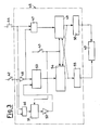
- Driving motor 40 and thus the speed permitted to the conveyor belt 31 by the differential 39, is controlled by the device of Fig. 3, which, in its turn, is connected to two microswitches 42 and 43 associated to a cam 41 integral with the drive-transfer shaft 18 (and is thus in correct phase with the feed of the articles 1) and with a photoelectric cell system 44 arranged along the route of the film 3 from the bobbin 30 to the conveyor belt 31 for detecting the run of the reference symbols 7 on the film.
- the position of the photoelectric cell 44 is so selected as to signal the run of the reference symbols 7 concurrently with the actuation of the microswith 42 if, and only if, the film 3 is correctly positioned relative to the articles 1.
- the signals delivered by the mi- croswitch 42 and by the photoelectric cell 44 synchronously with the feed of the articles 1 and the film 3, respectively, are processed by a comparison circuitry 45, which is comprised of two logical and gates, 46 and 47, the first with inputs directly associated with the photoelectric cell 44and the microswitch 42, and the se- bond with either input directly associated with the photoelectric cell 44 and the other input associated with the microswitch 42 via an inverter 48.
- a storage 49 which, via a timer 50, can apply to the motor 40 of the differential 39 a command for reducing the speed.
- a storage 51 is arranged, which via an inverter 52, can apply a cutoff command to a monostable multivibrator 53: this is driven by the microswitch 42 via inverter 48.
- the monostable 53 drives, in its turn, whenever it is enabled, a atorage 54, which, via a timer 55, is capable of applying a speed increase command to the motor 40 of the differential 39.
- the microswitch 43 has the task of providing to clearing the storages 49 and 54, each of which is also capable of providing to clear the other storage concurrently with the command of the attendant timer 50, 55.
- the storage 54 receives signals adapted to cause the motor 40 of the differential 39 to enter action, so that the conveyor belt 32 proceeds with its speed unaltered and the film 3 can thus maintain the correct phasing relationship with the articles 1.
- the photoelectric cell 44 signals the pass of a reference symbol 7 on the film 3 prior to the closing of the mi-croswitch 42, and this fact indicates that the film is in advance relative to the articles 1, at the output of and AND gate 47 a signal is generated which, stored in the storage 49 causes, via the timer 50, the energization of the motor 40 in the sense of reducing the speed of the conveyor belt 32 and consequently of the film 3.
- the photoelectric cell 44 signals the pass of a reference symbol 7 on the film 3 after that the closure period of the microswitch 42 is over, and this fact indicates that the film 3 is delayed relative to the articles,1
- none of the AND gates 46 and 47 delivers output signals and, conversely, the monostable multivibrator 53 is energized by the inverted signal of the microswitch 42 and produces via the storage 54 and the timer 55 the actuation of the motor 40 in the sense of increasing the speed of the conveyor belt 32 and thus that of the film 3. Every possible discrepancy of the film position from the correct phasing relationship with the articles 1 is thus automatically taken up.
Landscapes
- Engineering & Computer Science (AREA)
- Mechanical Engineering (AREA)
- Basic Packing Technique (AREA)
- Containers And Plastic Fillers For Packaging (AREA)
- Auxiliary Devices For And Details Of Packaging Control (AREA)
Abstract
Description
- This invention relates to a device for correctly positioning the film relative to the articles to be packaged in a packaging machine which employs a printed film as the article-wrapping means.
- Packaging machines are known which use a film of a plastics material for wrapping thereby articles in individual packets, which are sometimes caused closely to wrap the articles by heat welding.
- Until the film is totally devoid of any scripts or symbols, there is no problem in such machines which is bound to the mutual positioning of the articles and the film. The situation changes, instead, when the film is printed with symbols and/or scripts which must take, of necessity, an accurately defined position relative to the packaged articles. Even a slight mutual shift, as due for example to a different expansion of the film as the speed is varied, to frictional forces or mechanical sliding, may become deleterious, in fact, to the end of an attractive presentation of such articles.
- An object of the present invention is thus to provide a device which permits that the position of a printed film relative to the articles to be wrapped may be checked and possibly corrected prior to the article-wrapping operation.
- According to the invention, this object is achieved by a device which is characterized in that it comprises first means for detecting the position of the articles prior to their engagement by the printed film, second means for detecting the position of the printed symbols reported on sequential film sections prior to the engagement of said section with the respective articles to be wrapped, means for comparison of the indication of said first and said second detecting means, and actuating means controlled by said comparison means to vary the feeding speed of the film relative to the speed at which said articles are forwarded, and vice versa, in the case in which the indications of said first detecting means do not coincide with those of said second detecting means.
- Stated otherwise, the device according to the invention is based on the principle of checking the relative phase between the articles and the symbols printed upon the film and of varying the feeding speed of the articles, or of the film, in the case in which the phasing which has been detected does not correspond to the one which is expected. It becomes thus possible to ensure an accurate positioning of the articles relative to the printed film.
- To make the invention more clearly understood, a possible practical embodiment and application of the device of this invention is shown by way of example only in the accompanying drawings, wherein:
- Fig. 1 shows a diagrammatical elevational view of a packaging machine which comprises a positioning-control device according to the invention.
- Fig. 2 diagrammatically shows in plan view the packaging machine aforementioned, and
- Fig. 3 is a block diagram of an exemplary device = according to the invention.
- Figures 1 and 2 diagrammatically show a packaging machine of conventional make, which feeds, one at a time, the articles, 1, to be packaged, to a wrapping station, 2, wherein the articles are wrapped by
individual film sections 3, to be subsequently severed from each other by a cutting blade 4 which welds them and coacts with acounterblade 5. - As shown in Fig. 2, the articles 1 comprise a section, 6, for example an addressing label, which is intended to take an accurately defined position relative to a corresponding section 7 (for example a transparent window) which is present in each of the
film sections 3. It is thus required that the feed of the articles 1 is in exact phasing relationship with that of thefilm 3. - The articles 1 are drawn from a
hopper 29, wherein they are superposedly stacked, by means of two couples of motor-drivenrollers 21 and a plate 8 reciprocated horizontally by a lever 9 pivoted at 10 and driven by a rod 11. The latter, in turn, is driven by awheel 12 arranged eccentrically on a pivotal pin 13: a pinion 14 is axially mounted on 13. A driving dhain 15 connects pinion 14 to another pinion 16: the latter, via a bevel gear 17 receives the drive from a drive-transfer shaft 18 which, in its turn is rotated by amotor 19 through a chain drive-transfer 20. The drive-transfer shaft 18 also delivers, via abevel gear 22 and achain drive 23, the command for the drive of a conveyor 24: this has pushingdogs 25 evenly spaced apart along abelt 26 and the pushing dogs thus are fed one after the other at regular intervals and fed, on aplane 27 fitted with a longitudinal slot 28 (Fig. 2) the articles, 1, as they are drawn from thehopper 29. - The
film 3, in its turn, is paid off of abobbin 30 ùp to aconveyor belt 31, so as to receive thereon, in correspondence with the sequential film sections, the several article to be wrapped. By the agency of properly shaped guiding means, which are conventional and thus are not shown in the drawings hereof, thefilm 3 is folded around and above the articles 1, whereafter it is welded and, in addition, subjected to a double welded seam between an article and its next and to a cut therebetween by the action of the blade 4 andcounterblade 5. While 5 is fixed in apace, blade 4 has a reciprocation relative to thecounterblade 5, by exploiting a conventional actuator the details of which are disclosed, inter alia, in the US 3,758,366. The blade 4 receives the drive via arod 32 and a crank 33: the latter is driven to rotation by the drive-transfer shaft 18 via abevel gear 34, achain drive 35, and agearing 36. Thebevel gear 34 drives also theconveyor belt 31, via twochain drives output speed differential 39 equipped with acontrol motor 40. - Driving
motor 40, and thus the speed permitted to theconveyor belt 31 by thedifferential 39, is controlled by the device of Fig. 3, which, in its turn, is connected to twomicroswitches cam 41 integral with the drive-transfer shaft 18 (and is thus in correct phase with the feed of the articles 1) and with aphotoelectric cell system 44 arranged along the route of thefilm 3 from thebobbin 30 to theconveyor belt 31 for detecting the run of thereference symbols 7 on the film. The position of thephotoelectric cell 44 is so selected as to signal the run of thereference symbols 7 concurrently with the actuation of themicroswith 42 if, and only if, thefilm 3 is correctly positioned relative to the articles 1. - As shown in Fig. 3, the signals delivered by the mi-
croswitch 42 and by thephotoelectric cell 44 synchronously with the feed of the articles 1 and thefilm 3, respectively, are processed by acomparison circuitry 45, which is comprised of two logical and gates, 46 and 47, the first with inputs directly associated with the photoelectric cell 44and themicroswitch 42, and the se- bond with either input directly associated with thephotoelectric cell 44 and the other input associated with themicroswitch 42 via aninverter 48. At the output of theAND gate 47 there is arranged astorage 49 which, via atimer 50, can apply to themotor 40 of the differential 39 a command for reducing the speed. At the output of theAND gate 46, conversely, astorage 51 is arranged, which via aninverter 52, can apply a cutoff command to a monostable multivibrator 53: this is driven by the microswitch 42 viainverter 48. The monostable 53 drives, in its turn, whenever it is enabled, aatorage 54, which, via atimer 55, is capable of applying a speed increase command to themotor 40 of thedifferential 39. Themicroswitch 43 has the task of providing to clearing thestorages attendant timer - The result is the following mode of operation of the control device of Fig. 3. If the
photoelectric cell 44 signals the pass of areference symbol 7 of the film 3 (more detailedly, if in the case considered in Fig. 2 the rear edge of the window 7) while themicroswitch 42 is closed by thecam 41 and this fact indicates that thefilm 3 is correctly phased relative to the articles 1, theAND gate 47 does not deliver any output to thestorage 49, whereas theAND gate 46 delivers an output for the storage 51: the latter, via theinverter 48 cuts off themonostable multivibrator 53. Thus, not even thestorage 54 receives signals adapted to cause themotor 40 of thedifferential 39 to enter action, so that theconveyor belt 32 proceeds with its speed unaltered and thefilm 3 can thus maintain the correct phasing relationship with the articles 1. If, conversely, thephotoelectric cell 44 signals the pass of areference symbol 7 on thefilm 3 prior to the closing of the mi-croswitch 42, and this fact indicates that the film is in advance relative to the articles 1, at the output of and AND gate 47 a signal is generated which, stored in thestorage 49 causes, via thetimer 50, the energization of themotor 40 in the sense of reducing the speed of theconveyor belt 32 and consequently of thefilm 3. If, lastly, thephotoelectric cell 44 signals the pass of areference symbol 7 on thefilm 3 after that the closure period of themicroswitch 42 is over, and this fact indicates that thefilm 3 is delayed relative to the articles,1, none of theAND gates monostable multivibrator 53 is energized by the inverted signal of themicroswitch 42 and produces via thestorage 54 and thetimer 55 the actuation of themotor 40 in the sense of increasing the speed of theconveyor belt 32 and thus that of thefilm 3. Every possible discrepancy of the film position from the correct phasing relationship with the articles 1 is thus automatically taken up.
Claims (5)
Priority Applications (1)
| Application Number | Priority Date | Filing Date | Title |
|---|---|---|---|
| AT80200326T ATE10470T1 (en) | 1979-04-24 | 1980-04-11 | DEVICE FOR CORRECTLY ALIGNING A SINGLE SYMBOL-BEARING THERMOPLASTIC TAPE WITH RESPECT TO INDIVIDUAL ITEMS TO BE PACKAGED IN A PACKAGING MACHINE. |
Applications Claiming Priority (2)
| Application Number | Priority Date | Filing Date | Title |
|---|---|---|---|
| IT22145/79A IT1112724B (en) | 1979-04-24 | 1979-04-24 | DEVICE TO CONTROL THE POSITION OF THE FILM COMPARED TO THE PRODUCTS TO BE PACKED IN A PACKAGING MACHINE USING A PRINTED FILM |
| IT2214579 | 1979-04-24 |
Publications (3)
| Publication Number | Publication Date |
|---|---|
| EP0018041A2 true EP0018041A2 (en) | 1980-10-29 |
| EP0018041A3 EP0018041A3 (en) | 1980-11-12 |
| EP0018041B1 EP0018041B1 (en) | 1984-11-28 |
Family
ID=11192155
Family Applications (1)
| Application Number | Title | Priority Date | Filing Date |
|---|---|---|---|
| EP80200326A Expired EP0018041B1 (en) | 1979-04-24 | 1980-04-11 | Device for correctly positioning a single thermoplastic film bearing symbols with respect to individual articles to be packaged in a packaging machine |
Country Status (5)
| Country | Link |
|---|---|
| US (1) | US4381637A (en) |
| EP (1) | EP0018041B1 (en) |
| AT (1) | ATE10470T1 (en) |
| DE (1) | DE3069689D1 (en) |
| IT (1) | IT1112724B (en) |
Cited By (14)
| Publication number | Priority date | Publication date | Assignee | Title |
|---|---|---|---|---|
| EP0083913A1 (en) * | 1982-01-05 | 1983-07-20 | ALISYNCRO S.p.A. | System for regulating the feed of articles to a wrapping machine |
| EP0084299A1 (en) * | 1982-01-05 | 1983-07-27 | ALISYNCRO S.p.A. | System for regulating the feed of articles to a wrapping machine |
| EP0109819A3 (en) * | 1982-11-12 | 1985-11-21 | Doboy Packaging Machinery Inc. | Finwheel servo drive for packaging machine |
| FR2584054A1 (en) * | 1985-06-26 | 1987-01-02 | Sitma Spa | DEVICE FOR CONTROLLING THE RUNNING OF A PLASTIC FILM IN A PACKAGING MACHINE. |
| EP0209184A3 (en) * | 1985-07-17 | 1988-05-25 | SITMA S.p.A. | Centralised drive device in a packaging machine |
| US4807420A (en) * | 1985-12-24 | 1989-02-28 | Barker Michael J | Horizontal form-fill-seal packaging machines |
| EP0537844A1 (en) * | 1991-10-14 | 1993-04-21 | SITMA S.p.A. | Apparatus for stretching a continuous plastics film in a packaging machine |
| FR2719522A1 (en) * | 1994-05-06 | 1995-11-10 | Ghesquieres Sa Bernard | Method of mfg. window envelopes from opaque material band |
| EP0526944B1 (en) * | 1991-08-05 | 1996-02-07 | SITMA S.p.A. | Apparatus for applying adhesive onto a web of packaging material |
| EP0759357A1 (en) * | 1995-08-23 | 1997-02-26 | Sopaprofipap, S.A.S. | Method and machine for making window envelopes around a document |
| EP1914165A1 (en) | 2004-06-02 | 2008-04-23 | Ferag AG | Method and device for forming a row of flat objects |
| CH699875A1 (en) * | 2008-11-13 | 2010-05-14 | Ferag Ag | Device and method for forming a hose from a web of material. |
| EP2716557A3 (en) * | 2012-10-05 | 2015-07-29 | Pitney Bowes Inc. | System for dynamically adjusting the relative position of internal content material in a mailpiece fabrication system |
| CN114162385A (en) * | 2022-02-11 | 2022-03-11 | 深圳市兴禾自动化股份有限公司 | Full-automatic film coating device and process for battery |
Families Citing this family (27)
| Publication number | Priority date | Publication date | Assignee | Title |
|---|---|---|---|---|
| NL8101588A (en) * | 1981-03-31 | 1982-10-18 | Tevopharm Schiedam Bv | METHOD AND APPARATUS FOR ATTACHING PACKAGING MATERIALS TOGETHER. |
| US4565045A (en) * | 1982-03-11 | 1986-01-21 | Shigeru Ikemoto | Wrapping device |
| US4549386A (en) * | 1983-04-18 | 1985-10-29 | Baker Perkins Holdings Plc | Form-fill-seal wrapping apparatus |
| US4554774A (en) * | 1983-04-30 | 1985-11-26 | Shibuya Kogyo Co., Ltd. | System for synchronizing two or more process units |
| JPS6011347A (en) * | 1983-06-30 | 1985-01-21 | 株式会社古川製作所 | Method and device for making bag |
| US4546597A (en) * | 1983-10-05 | 1985-10-15 | Doboy Packaging Machinery, Inc. | Transfer assembly for literature wrapping equipment |
| US4574566A (en) * | 1985-01-14 | 1986-03-11 | Doboy Packaging Machinery, Inc. | Wrapping machine and method |
| IT206321Z2 (en) * | 1985-09-24 | 1987-08-10 | Sitma | LONGITUDINAL WELDING EQUIPMENT IN A PACKAGING MACHINE. |
| US4712357A (en) * | 1985-10-28 | 1987-12-15 | Fmc Corporation | Computer controlled horizontal wrapper |
| US4722168A (en) * | 1987-06-25 | 1988-02-02 | Doboy Packaging Machinery, Inc. | Product-out-of-registration control for high speed wrapping machine |
| US4828109A (en) * | 1987-08-25 | 1989-05-09 | Alza Corporation | Package having fiber-containing sheath and apparatus and method for packaging |
| US4876842A (en) * | 1988-01-15 | 1989-10-31 | Minigrip, Inc. | Method of and apparatus for packaging product masses in a form, fill and seal machine |
| IT1248310B (en) * | 1991-05-17 | 1995-01-05 | Sitma Spa | LONGITUDINAL WELDING EQUIPMENT IN A PACKAGING MACHINE |
| US5821724A (en) * | 1995-02-03 | 1998-10-13 | Cms Gilbreth Packaging Systems | Feedback limiter for closed loop motor controller |
| US6029957A (en) * | 1994-02-01 | 2000-02-29 | Furniture Row Technologies, Llc | Manufacture of pocket spring assemblies |
| US6315275B1 (en) | 1995-09-18 | 2001-11-13 | Furniture Row Technologies, Llc | Pocket spring assembly and methods |
| US5840243A (en) | 1996-06-17 | 1998-11-24 | Gillette Canada Inc. | Method of forming blister pack packaging |
| US6739107B1 (en) | 2001-02-28 | 2004-05-25 | Paramount Bedding, Inc. | Method and apparatus for compressing a mattress with an inner coil spring |
| US6889398B2 (en) * | 2002-06-17 | 2005-05-10 | Paramount Bedding, Inc. | Coil spring containing mattress and method |
| NL1023745C2 (en) * | 2003-06-25 | 2004-12-28 | Buhrs Zaandam Bv | Feeder equipped with automatic format recognition. |
| ITMI20040831A1 (en) * | 2004-04-27 | 2004-07-27 | Sitma Spa | PROCEDURE FOR FEEDING PRODUCTS OF HEIGHT AND VARIABLE LENGTH IN A CONTINUOUS PACKAGING EQUIPMENT |
| DE102006045087A1 (en) * | 2006-09-21 | 2008-03-27 | Focke & Co.(Gmbh & Co. Kg) | Method and device for handling diapers |
| CN102431817A (en) * | 2010-08-31 | 2012-05-02 | 海德堡印刷机械股份公司 | Transporting apparatus |
| US20130097965A1 (en) | 2011-10-21 | 2013-04-25 | Rethceif Enterprises, Llc | Apparatus for forming elongate plastic film into a tube around variable size articles |
| ITMI20130406A1 (en) * | 2013-03-18 | 2014-09-19 | Sitma Machinery S P A | BENDING UNIT OF A CONTINUOUS SHEET IN PACKAGING MATERIAL, IN PARTICULAR PAPER, APPLICABLE TO AUTOMATIC PACKAGING MACHINES AND AUTOMATIC PACKAGING MACHINE INCLUDING SUCH A BENDING UNIT |
| JP6583341B2 (en) * | 2017-04-14 | 2019-10-02 | オムロン株式会社 | Packaging machine, control device for packaging machine, control method, and program |
| US20240308703A1 (en) * | 2023-02-21 | 2024-09-19 | Intertape Polymer Corp. | Packaging apparatus and method of use |
Family Cites Families (10)
| Publication number | Priority date | Publication date | Assignee | Title |
|---|---|---|---|---|
| US3126431A (en) * | 1964-03-24 | harder etal | ||
| US2296142A (en) * | 1940-08-02 | 1942-09-15 | Samuel J Campbell | Packaging machinery |
| US2977730A (en) * | 1958-08-11 | 1961-04-04 | Lynch Corp | Wrapper registration control |
| US3022618A (en) * | 1959-11-12 | 1962-02-27 | Johnson & Johnson | Machine suitable for packaging and like functions |
| US3075328A (en) * | 1961-03-09 | 1963-01-29 | Battle Creek Packaging Machine | Pouch area marking control for pouch packaging machines |
| US3397505A (en) * | 1965-03-15 | 1968-08-20 | Eastman Kodak Co | Packaging machine |
| DE1461923C3 (en) * | 1965-07-09 | 1974-02-21 | Hoefliger + Karg, 7050 Waiblingen | Device for registering two film webs enclosing a product |
| US3589095A (en) * | 1968-05-09 | 1971-06-29 | Hayssen Mfg Co | Method and apparatus for registering two separate webs of wrapping material |
| US3762125A (en) * | 1971-03-17 | 1973-10-02 | Morrell & Co John | Film registration apparatus |
| US3789574A (en) * | 1971-04-12 | 1974-02-05 | Gen Films Inc | Packaging machine |
-
1979
- 1979-04-24 IT IT22145/79A patent/IT1112724B/en active
-
1980
- 1980-04-11 DE DE8080200326T patent/DE3069689D1/en not_active Expired
- 1980-04-11 EP EP80200326A patent/EP0018041B1/en not_active Expired
- 1980-04-11 AT AT80200326T patent/ATE10470T1/en not_active IP Right Cessation
- 1980-04-15 US US06/140,597 patent/US4381637A/en not_active Expired - Lifetime
Cited By (19)
| Publication number | Priority date | Publication date | Assignee | Title |
|---|---|---|---|---|
| EP0084299A1 (en) * | 1982-01-05 | 1983-07-27 | ALISYNCRO S.p.A. | System for regulating the feed of articles to a wrapping machine |
| EP0083913A1 (en) * | 1982-01-05 | 1983-07-20 | ALISYNCRO S.p.A. | System for regulating the feed of articles to a wrapping machine |
| EP0109819A3 (en) * | 1982-11-12 | 1985-11-21 | Doboy Packaging Machinery Inc. | Finwheel servo drive for packaging machine |
| FR2584054A1 (en) * | 1985-06-26 | 1987-01-02 | Sitma Spa | DEVICE FOR CONTROLLING THE RUNNING OF A PLASTIC FILM IN A PACKAGING MACHINE. |
| EP0209184A3 (en) * | 1985-07-17 | 1988-05-25 | SITMA S.p.A. | Centralised drive device in a packaging machine |
| US4807420A (en) * | 1985-12-24 | 1989-02-28 | Barker Michael J | Horizontal form-fill-seal packaging machines |
| EP0526944B1 (en) * | 1991-08-05 | 1996-02-07 | SITMA S.p.A. | Apparatus for applying adhesive onto a web of packaging material |
| EP0537844A1 (en) * | 1991-10-14 | 1993-04-21 | SITMA S.p.A. | Apparatus for stretching a continuous plastics film in a packaging machine |
| US5285621A (en) * | 1991-10-14 | 1994-02-15 | Sitma S.P.A. | Apparatus for stretching a continuous plastics film in a packaging machine |
| FR2719522A1 (en) * | 1994-05-06 | 1995-11-10 | Ghesquieres Sa Bernard | Method of mfg. window envelopes from opaque material band |
| EP0759357A1 (en) * | 1995-08-23 | 1997-02-26 | Sopaprofipap, S.A.S. | Method and machine for making window envelopes around a document |
| EP1914165A1 (en) | 2004-06-02 | 2008-04-23 | Ferag AG | Method and device for forming a row of flat objects |
| US7757461B2 (en) | 2004-06-02 | 2010-07-20 | Ferag Ag | Method and device packaging flat objects |
| US7877965B2 (en) | 2004-06-02 | 2011-02-01 | Ferag Ag | Method and device packaging flat objects |
| CH699875A1 (en) * | 2008-11-13 | 2010-05-14 | Ferag Ag | Device and method for forming a hose from a web of material. |
| WO2010054489A1 (en) * | 2008-11-13 | 2010-05-20 | Ferag Ag | Device and method for forming a tube from a material web |
| EP2716557A3 (en) * | 2012-10-05 | 2015-07-29 | Pitney Bowes Inc. | System for dynamically adjusting the relative position of internal content material in a mailpiece fabrication system |
| US9714102B2 (en) | 2012-10-05 | 2017-07-25 | Pitney Bowes Inc. | Method and system for dynamically adjusting the relative position of internal content material in a mailpiece fabrication system |
| CN114162385A (en) * | 2022-02-11 | 2022-03-11 | 深圳市兴禾自动化股份有限公司 | Full-automatic film coating device and process for battery |
Also Published As
| Publication number | Publication date |
|---|---|
| DE3069689D1 (en) | 1985-01-10 |
| US4381637A (en) | 1983-05-03 |
| EP0018041B1 (en) | 1984-11-28 |
| EP0018041A3 (en) | 1980-11-12 |
| IT1112724B (en) | 1986-01-20 |
| IT7922145A0 (en) | 1979-04-24 |
| ATE10470T1 (en) | 1984-12-15 |
Similar Documents
| Publication | Publication Date | Title |
|---|---|---|
| US4381637A (en) | Device for correctly positioning the film relative to the articles to be wrapped in a packaging machine | |
| US5671593A (en) | Semiautomatic package wrapping machine | |
| CA1299704C (en) | Product-out-of-registration control for high speed wrapping machine | |
| CN1020184C (en) | Equipment for wrapping article or material | |
| US4338768A (en) | Automatic machine for sorting items of correspondence, particularly magazines, into batches each having a different general destination | |
| US2199708A (en) | Method of and apparatus for feeding web material | |
| JPS62215456A (en) | Method and mechanism foor feeding material web | |
| US3751875A (en) | Apparatus for filling, sealing and dispensing bags | |
| EP0712782A1 (en) | Apparatus for wrapping articles with a strip of wrapping material | |
| US2951325A (en) | Sealing and severing mechanism | |
| EP0044820A1 (en) | A machine and a process for packaging articles of products | |
| US3706183A (en) | Rotary heat-sealing and cut-off mechanism | |
| US7568511B2 (en) | Synchronized stamp applicator machine and method of operating the same | |
| EP0084299A1 (en) | System for regulating the feed of articles to a wrapping machine | |
| US2871639A (en) | Wrapper indexing mechanism for wrapping machines | |
| US3212229A (en) | Film packaging arrangement | |
| US3283474A (en) | Bag tying machine | |
| USRE29362E (en) | Packaging apparatus | |
| US20050034580A1 (en) | Device for transversally cutting into portions a continuous strip of containers | |
| CN109305413A (en) | A kind of double plastics spoon townhouse packing machine and packing method | |
| US3656273A (en) | Wrapping machine | |
| US3416289A (en) | Apparatus for wrapping cigarette packs and the like | |
| US2740244A (en) | Bag sealing machine | |
| US4075816A (en) | Wrapper sheet feed for wrapping machine | |
| JPH0366208B2 (en) |
Legal Events
| Date | Code | Title | Description |
|---|---|---|---|
| PUAI | Public reference made under article 153(3) epc to a published international application that has entered the european phase |
Free format text: ORIGINAL CODE: 0009012 |
|
| PUAL | Search report despatched |
Free format text: ORIGINAL CODE: 0009013 |
|
| AK | Designated contracting states |
Designated state(s): AT BE CH DE FR GB IT LU NL SE |
|
| AK | Designated contracting states |
Designated state(s): AT BE CH DE FR GB IT LU NL SE |
|
| 17P | Request for examination filed |
Effective date: 19810414 |
|
| ITF | It: translation for a ep patent filed | ||
| GRAA | (expected) grant |
Free format text: ORIGINAL CODE: 0009210 |
|
| AK | Designated contracting states |
Designated state(s): AT BE CH DE FR GB IT LI LU NL SE |
|
| REF | Corresponds to: |
Ref document number: 10470 Country of ref document: AT Date of ref document: 19841215 Kind code of ref document: T |
|
| REF | Corresponds to: |
Ref document number: 3069689 Country of ref document: DE Date of ref document: 19850110 |
|
| ET | Fr: translation filed | ||
| PLBE | No opposition filed within time limit |
Free format text: ORIGINAL CODE: 0009261 |
|
| STAA | Information on the status of an ep patent application or granted ep patent |
Free format text: STATUS: NO OPPOSITION FILED WITHIN TIME LIMIT |
|
| 26N | No opposition filed | ||
| ITPR | It: changes in ownership of a european patent |
Owner name: CAMBIO RAGIONE SOCIALE;SITMA S.P.A. |
|
| REG | Reference to a national code |
Ref country code: GB Ref legal event code: 732 |
|
| NLS | Nl: assignments of ep-patents |
Owner name: SITMA S.P.A. TE SPILAMBERTO, ITALIE. |
|
| REG | Reference to a national code |
Ref country code: FR Ref legal event code: TP |
|
| REG | Reference to a national code |
Ref country code: CH Ref legal event code: PUE Owner name: SITMA S.P.A. |
|
| ITTA | It: last paid annual fee | ||
| REG | Reference to a national code |
Ref country code: FR Ref legal event code: EM |
|
| EPTA | Lu: last paid annual fee | ||
| EAL | Se: european patent in force in sweden |
Ref document number: 80200326.9 |
|
| PGFP | Annual fee paid to national office [announced via postgrant information from national office to epo] |
Ref country code: GB Payment date: 19980402 Year of fee payment: 19 |
|
| PGFP | Annual fee paid to national office [announced via postgrant information from national office to epo] |
Ref country code: BE Payment date: 19980416 Year of fee payment: 19 |
|
| PGFP | Annual fee paid to national office [announced via postgrant information from national office to epo] |
Ref country code: AT Payment date: 19980423 Year of fee payment: 19 |
|
| PGFP | Annual fee paid to national office [announced via postgrant information from national office to epo] |
Ref country code: CH Payment date: 19980427 Year of fee payment: 19 |
|
| PGFP | Annual fee paid to national office [announced via postgrant information from national office to epo] |
Ref country code: FR Payment date: 19980428 Year of fee payment: 19 |
|
| PGFP | Annual fee paid to national office [announced via postgrant information from national office to epo] |
Ref country code: SE Payment date: 19980429 Year of fee payment: 19 |
|
| PGFP | Annual fee paid to national office [announced via postgrant information from national office to epo] |
Ref country code: NL Payment date: 19980430 Year of fee payment: 19 Ref country code: LU Payment date: 19980430 Year of fee payment: 19 |
|
| PGFP | Annual fee paid to national office [announced via postgrant information from national office to epo] |
Ref country code: DE Payment date: 19980529 Year of fee payment: 19 |
|
| PG25 | Lapsed in a contracting state [announced via postgrant information from national office to epo] |
Ref country code: LU Free format text: LAPSE BECAUSE OF EXPIRATION OF PROTECTION Effective date: 19990411 Ref country code: GB Free format text: LAPSE BECAUSE OF NON-PAYMENT OF DUE FEES Effective date: 19990411 Ref country code: AT Free format text: LAPSE BECAUSE OF NON-PAYMENT OF DUE FEES Effective date: 19990411 |
|
| PG25 | Lapsed in a contracting state [announced via postgrant information from national office to epo] |
Ref country code: SE Free format text: LAPSE BECAUSE OF NON-PAYMENT OF DUE FEES Effective date: 19990412 |
|
| PG25 | Lapsed in a contracting state [announced via postgrant information from national office to epo] |
Ref country code: LI Free format text: LAPSE BECAUSE OF NON-PAYMENT OF DUE FEES Effective date: 19990430 Ref country code: CH Free format text: LAPSE BECAUSE OF NON-PAYMENT OF DUE FEES Effective date: 19990430 Ref country code: BE Free format text: LAPSE BECAUSE OF NON-PAYMENT OF DUE FEES Effective date: 19990430 |
|
| BERE | Be: lapsed |
Owner name: SITMA SOCIETA ITALIANA MACCHINE AUTOMATICHE S.P.A Effective date: 19990430 |
|
| PG25 | Lapsed in a contracting state [announced via postgrant information from national office to epo] |
Ref country code: NL Free format text: LAPSE BECAUSE OF NON-PAYMENT OF DUE FEES Effective date: 19991101 |
|
| GBPC | Gb: european patent ceased through non-payment of renewal fee |
Effective date: 19990411 |
|
| REG | Reference to a national code |
Ref country code: CH Ref legal event code: PL |
|
| PG25 | Lapsed in a contracting state [announced via postgrant information from national office to epo] |
Ref country code: FR Free format text: LAPSE BECAUSE OF NON-PAYMENT OF DUE FEES Effective date: 19991231 |
|
| NLV4 | Nl: lapsed or anulled due to non-payment of the annual fee |
Effective date: 19991101 |
|
| EUG | Se: european patent has lapsed |
Ref document number: 80200326.9 |
|
| REG | Reference to a national code |
Ref country code: FR Ref legal event code: ST |
|
| PG25 | Lapsed in a contracting state [announced via postgrant information from national office to epo] |
Ref country code: DE Free format text: LAPSE BECAUSE OF NON-PAYMENT OF DUE FEES Effective date: 20000201 |