EP0017392A1 - Latch mechanism for locking differential - Google Patents
Latch mechanism for locking differential Download PDFInfo
- Publication number
- EP0017392A1 EP0017392A1 EP80300853A EP80300853A EP0017392A1 EP 0017392 A1 EP0017392 A1 EP 0017392A1 EP 80300853 A EP80300853 A EP 80300853A EP 80300853 A EP80300853 A EP 80300853A EP 0017392 A1 EP0017392 A1 EP 0017392A1
- Authority
- EP
- European Patent Office
- Prior art keywords
- latch
- differential gear
- axis
- flyweight
- rotation
- Prior art date
- Legal status (The legal status is an assumption and is not a legal conclusion. Google has not performed a legal analysis and makes no representation as to the accuracy of the status listed.)
- Granted
Links
Images


Classifications
-
- F—MECHANICAL ENGINEERING; LIGHTING; HEATING; WEAPONS; BLASTING
- F16—ENGINEERING ELEMENTS AND UNITS; GENERAL MEASURES FOR PRODUCING AND MAINTAINING EFFECTIVE FUNCTIONING OF MACHINES OR INSTALLATIONS; THERMAL INSULATION IN GENERAL
- F16H—GEARING
- F16H48/00—Differential gearings
- F16H48/20—Arrangements for suppressing or influencing the differential action, e.g. locking devices
- F16H48/22—Arrangements for suppressing or influencing the differential action, e.g. locking devices using friction clutches or brakes
-
- F—MECHANICAL ENGINEERING; LIGHTING; HEATING; WEAPONS; BLASTING
- F16—ENGINEERING ELEMENTS AND UNITS; GENERAL MEASURES FOR PRODUCING AND MAINTAINING EFFECTIVE FUNCTIONING OF MACHINES OR INSTALLATIONS; THERMAL INSULATION IN GENERAL
- F16H—GEARING
- F16H48/00—Differential gearings
- F16H48/06—Differential gearings with gears having orbital motion
- F16H48/08—Differential gearings with gears having orbital motion comprising bevel gears
-
- F—MECHANICAL ENGINEERING; LIGHTING; HEATING; WEAPONS; BLASTING
- F16—ENGINEERING ELEMENTS AND UNITS; GENERAL MEASURES FOR PRODUCING AND MAINTAINING EFFECTIVE FUNCTIONING OF MACHINES OR INSTALLATIONS; THERMAL INSULATION IN GENERAL
- F16H—GEARING
- F16H48/00—Differential gearings
- F16H48/20—Arrangements for suppressing or influencing the differential action, e.g. locking devices
- F16H48/24—Arrangements for suppressing or influencing the differential action, e.g. locking devices using positive clutches or brakes
-
- F—MECHANICAL ENGINEERING; LIGHTING; HEATING; WEAPONS; BLASTING
- F16—ENGINEERING ELEMENTS AND UNITS; GENERAL MEASURES FOR PRODUCING AND MAINTAINING EFFECTIVE FUNCTIONING OF MACHINES OR INSTALLATIONS; THERMAL INSULATION IN GENERAL
- F16H—GEARING
- F16H48/00—Differential gearings
- F16H48/06—Differential gearings with gears having orbital motion
- F16H48/08—Differential gearings with gears having orbital motion comprising bevel gears
- F16H2048/085—Differential gearings with gears having orbital motion comprising bevel gears characterised by shafts or gear carriers for orbital gears
Definitions
- the present invention relates generally to differential mechanisms, and more particularly, to such mechanisms of the type commonly referred to as "locking differentials".
- Differential gear mechanisms of the type to which the present invention applies are broadly referred to as “limited slip differentials” and typically include a clutch pack which is operable to limit or retard differentiating action between the output gears (side gears). More specifically, however, the present invention is intended for use on limited slip differentials of the type referred to as “locking differentials", and will be described in connection therewith.
- a locking differential means are provided for engaging or locking the clutch set, rather than permitting it to slip, to substantially reduce the amount of differentiating action permitted between the side gears.
- Locking differentials of various types are now generally well known in the art, including both inter- axle lockers, and inter-wheel lockers.
- Inter-wheel locking differentials may be applied either to conventional rear-wheel drive vehicles, or to the more recent front-wheel drive vehicles.
- the present invention may be utilized to advantage in any of the above-described types of locking differential, it is especially advantageous when applied to an inter-wheel, front-wheel drive vehicle, and will be described in connection therewith.
- a locking differential In a locking differential, the space problem is con- pounded by the dimensional limitations imposed in regard to both the axial length and the gear case outside diameter. For example, the location of adjacent drive train components and accessories may result in a specified maximum case diameter, over at least a major portion of the axial extent of the locking differential.
- a lockup means for locking up the differential gear set, and an actuating means for actuating the lockup means.
- the actuating means includes a rotatable flyweight mechanism and a latch mechanism which is movable between an operative position and an inoperative position.
- the latch mechanism engages the flyweight mechanism to prevent rotation thereof and actuate the lockup means, and in the inoperative position, the latch mechanism is incapable of engaging the flyweights.
- the inoperative position occurs when the rotational speed of the differential gear case exceeds a predetermined limit. Normally, with no differentiation occurring between the side gears, the vehicle speed is a direct function of the gear case rotational speed.
- the performance of an actuating means of the type to which the present invention applies can be improved by increasing the size of the flyweight mechanism, and by increasing the weight of the latch mechanism.
- the flyweight mechanism and the latch mechanism have been disposed circumferentially adjacent each other, and in a locking differential for a front-wheel drive vehicle, requiring a reduced case diameter, there would be insufficient space to utilize the prior art arrangement, with the flyweight and latch mechanisms adjacent each other, unless the size and weight of the mechanisms would be reduced, which would adversely effect the performance.
- Performance of a locking differential is evaluated primarily in terms of "missed engagements", i.e., the number of times that one of the wheels “spins out” or accelerates, without the latch mechanism engaging the flyweight mechanism to initiate locking of the differential gear set.
- Missed engagements i.e., the number of times that one of the wheels “spins out” or accelerates
- One of the primary causes of missed engagement is the effect of gravity on the weighted portion of the latch mechanism. For example, if the latch mechanism is designed not to engage at case rotational speeds above 200 rpm, the actual maximum engagement speed will vary depending upon the rotational orientation of the differential case at the instant the flyweights move to the extended position.
- a graph of case rotational speed (maximum speed at which engagement can occur) versus rotational orientation is shaped generally like a sine wave, with the amplitude of the curve indicating the relative effect of gravity on the operation of the latch mechanism.
- This sine wave may also be considered as a graph of case speed above which lockout of the latch mechanism (i.e., movement of the latch mechanism to an inoperative position) will occur, and therefore, will be referred to hereinafter, for simplicity, as the "lockout" curve.
- flyweights are designed to move to the extended position at 100 rpm difference between the side gears, no engagement can occur at case speeds below 50 rpm (the average of the side gear speeds).
- a line may then be placed on the above-mentioned graph at the 50 rpm level. Evaluation of this graph indicates that engagement will not occur at case speeds above the "lockout” curve, nor below the 50 rpm line. If the "lockout" curve dips below the 50 rpm line, over a range of case orientations, the indicated result is that engagement cannot occur within that particular range of rotational orientations, resulting in a spin out or acceleration.
- the attempts to reduce the amplitude of the engagement curve are related to the previously-described size and space problems involved in the design of locking differentials for front-wheel drive vehicles. It has been found that the amplitude of the lockout curve is related to the geometry of the latch mechanism, and more specifically, to the center of gravity (CG) of the weighted portion of the latch mechanism.
- CG center of gravity
- R One of the factors involved in the radius (R), i.e., the distance from the axis of rotation of the differential to the CG of the weight, when the latch mechanism is in the operative position, i.e., the position in which engagement of the flyweights can occur. As R increases, the amplitude of the curve decreases.
- a differential gear mechanism including a lockup means for locking up the differential gear means to retard differentiating action and an actuating means for actuating the lockup means.
- the lockup means includes clutch means and a cam means
- the actuating means includes retarding means operable to engage the cam means and retard rotation of a portion thereof.
- the retarding means comprises a flyweight mechanism rotatable about its axis at a speed generally proportional to the level of differentiating action.
- the flyweight mechanism defines a stop surface movable from a retracted position to an extended position in response to an increase in the level of differentiating action.
- the actuating means further includes a latch mechanism including a latch member and means biasing the latch member toward an operative position. When the latch member is in the operative position, it is disposed to engage the stop surface, with the stop surface in the extended position.
- the latch mechanism further includes a weight oppositely disposed from the latch member, about the axis of rotation, the weight being operable to move the latch mechanism in opposition to the biasing means along a straight, generally diametrally-orientated path in response to an increasing rotational speed of the differential gear mechanism. Above a predetermined rotational speed of the mechanism, the weight is operable to move the latch member from its operative position to an inoperative position, incapable of engaging the stop surface of the flyweight mechanism.
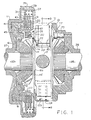
- FIG. 1 is an axial cross section of a differential gear mechanism made in accordance with the present invention.
- the differential gear mechanism includes a gear case comprising a lefthand casing section 11 and a righthand casing section 13. Torque input to the gear mechanism is typically by means of an input gear (not shown), which may be bolted to the casing section 13.
- a differential gear set including a pair of planet pinions 15 (see FIG. 2), rotatably mounted on a pinion shaft 17 which, in turn, is pinned to the casing section 13.
- the planet pinions 15 comprise the input gears of the differential gear set and are in meshing engagement with a pair of side gears 19 and 21, which comprise the output gears of the differential gear set.
- the side gears 19 and 21 are splined to a pair of axle shafts 23 and 25, respectively.
- the casing sections 11 and 13 include annular hub portions 27 and 29, respectively, on which are mounted the bearing sets (not shown) used to provide rotational support for the differential gear mechanism, relative to the main, outer casing (not shown).
- the differential gear mechanism of the present invention is provided with a lockup means for locking up the differential gear set, and an actuating means for actuating the lockup means.
- the lockup means comprises a clutch mechanism including a plurality of clutch discs 31 and a plurality of clutch discs 33.
- the casing section 13 defines a plurality of semi-cylindrical openings 35.
- there are four of the openings 35, and disposed within each opening is a semi-cylindrical guide member 37 which helps to guide the clutch discs 31.
- a helical compression spring 39 Disposed within each of the guide members 37 is a helical compression spring 39 which seats, at its opposite ends, against the lefthand and righthand clutch discs 31.
- the biasing force exerted by the springs 39 must be sufficient to maintain the clutch discs 31 and 33 in the disengaged condition shown in FIG. 1, in the absence of other forces biasing the clutch discs together.
- the lockup means further includes a cam mechanism, generally designated 41.
- a cam mechanism As is well known to those skilled in the locking differential art, one function of the cam mechanism 41 is to effect movement of the clutch pack from the disengaged condition shown in FIG. 1 to an engaged condition. It will become apparent from the subsequent description that, within the scope of the present invention, many different configurations and types of cam mechanism may be utilized. In the subject embodiment, the cam mechanism 41 is of the type illustrated and described in greater detail in copending European Patent Application No. (Jenkins & Co. Reference J. 147671.
- the cam mechanism 41 includes a main cam member 43 and an intermediate cam member 45.
- the main cam member 43 defines a set of external splines 47
- the clutch discs 33 define a set of internal splines such that the clutch discs 33 are splined to the main cam member 43 for rotation therewith.
- the intermediate cam member 45 defines a set of straight, internal splines 51 which are in meshing engagement with a set of straight, external splines 53, formed about the outer periphery of the side gear 19.
- the intermediate cam member 45 is splined to the side gear 19 for rotation therewith, such that the forces transmitted from the intermediate cam member 45 to the side gear 19 are only rotational, with no substantial axial forces being transmitted to the side gear 19.
- the intermediate cam member 45 defines a plurality of cam ramp surfaces 57
- the main cam member 43 defines a plurality of cam ramp surfaces 61.
- the relative rotational position of the cam members 43 and 45, wherein the cam ramp surfaces 57 and 61 are in meshing engagement, corresponds to the disengaged condition of the clutch mechanism shown in FIG. 1.
- the cam members 43 and 45 remain in that relative rotational position, and rotate with the side gear 19, at the same rotational speed.
- movement of the clutch mechanism to the engaged condition may be accomplished by retarding rotation of the main cam member 43, relative to the intermediate cam member 45. Such relative rotation between the cam members 43 and 45 will cause “ramping" of the ramp surfaces 57 and 61, resulting in axial movement of the main cam member 43, to the right in FIG. 1. Such movement of the cam member 43 is in opposition to the biasing force of the springs 39.
- the lockup means utilized with the present invention is of the "self-energizing" type, i.e., the coefficient of friction of the discs 31 and 33 and the cam angle (angle of ramp surfaces 57 and 61) are selected such that the cam member 43 would ramp and lock the clutch pack merely as a result of frictional drag between the discs, in the absence of the springs 39.
- the springs 39 prevent the discs from exerting sufficient drag on the cam member 43 to cause it to ramp.
- ramping and locking of the clutch pack will occur.
- the lockup means will remain actuated (with the differential gear set locked up) until the torque difference across the lockup means is substantially eliminated (e.g., both wheels turning at the same speed, with full traction), at which time the springs disengage the clutch pack.
- the actuating means utilized with the present invention includes a retarding mechanism.
- the retarding mechanism comprises a flyweight mechanism, generally designated 71.
- the flyweight mechanism 71 could have many different configurations, but in the subject embodiment, it is made in accordance with U. S. Pat. Nos. Re. 28,004 and 3,985,045, both of which are assigned to the assignee of the present invention.
- the flyweight mechanism 71 includes a main shaft 73 on which is mounted a pair of cone clutch members 75 and 77.
- a pair of endcaps 79 and 81 are biased into engagement with the cone clutch members 75 and 77, respectively, by a compression spring 83.
- Also disposed about the support shaft 85 is a spacer 91, and disposed between the flyweights 87 and 89 is a torsional spring member 93.
- the spring member 93 includes a pair of end portions 95 and 97, which engage the flyweights 87 and 89, respectively, to maintain the flyweights in the retracted position shown in FIG. 4, in the absence of centrifugal force.
- an externally- toothed gear member 101 which is in engagement with a set of internal gear teeth 103 formed about the inner periphery of the main cam member 43, as is described in greater detail in the above-referenced copending application.
- a bracket member 105 is rigidly attached to the casing section 13 by four machine screws 107.
- the bracket member 105 defines a generally circular central opening 109, and a straight-sided opening 110, disposed above the opening 109 and contiguous therewith. The function of the opening 110 will be described subsequently.
- the bracket member 105 further defines a circular opening which receives and supports the cone clutch 75 and main shaft 73 of the flyweight mechanism 71, with the opposite end of the main shaft 73 being rotatably supported by the casing section 13. Therefore, the flyweight mechanism 71 is mounted for rotation about its own axis.
- the actuating means of the present invention includes a stop means (or latch means), operable to prevent rotation of the flyweight mechanism 71, when a predetermined level of differentiating action occurs.
- a stop means or latch means
- the additional retarding force thereby applied to the main cam member 43 is sufficient to overcome the biasing force of the springs 39, resulting in lockup of the clutch pack.
- the stop means or latch means of the present invention comprises a novel latch mechanism, generally designated 111.
- the latch mechanism 111 includes a one-piece, stamped frame member 113, including an arcuate latch member 115 which, as may be seen in FIG. 1, extends toward the bracket member 105.
- the latch member 115 includes a guide tab 116 which is movably disposed (up and down in FIGS. 1 and 2) within the opening 110, to help maintain orientation of the latch mechanism 111 relative to the bracket member 105, during operating conditions which will be described subsequently.
- the latch mechanism 111 further includes a weighted member 117 which is attached to the frame member 113 by means of a rivet 119.
- the weighted member 117 defines a cylindrical bore 121 within which is seated a compression spring 123 (FIGS. 1 and 8). The other end of the spring 123 is seated against a lower, L--shaped portion 124 of the bracket member 105.
- the latch member 115 includes a pair of oppositely disposed latch surfaces 125 and 127 which are effective to prevent rotation of the latch mechanism 71 in a manner to be described subsequently.
- the torsion spring 93 is effective to maintain the flyweights 87 and 89 in the retracted position of FIG. 4.
- the compression spring 123 biases the latch mechanism 111 toward the flyweight mechanism 71, such that the latch member 115 is in the position shown in FIGS. 3 and 4, either touching the end caps 79 and 81 or being closely spaced apart therefrom.
- flyweights 87 and 89 When the level of differentiating action exceeds a predetermined limit, centrifugal force causes the flyweights 87 and 89 to overcome the biasing force of the spring 93 and move outwardly to the position shown in FIG. 5.
- the flyweights 87 and 89 define stop surfaces 129 and 131, respectively, which are in the extended position, with the flyweights disposed outwardly as shown in FIG. 5.
- one of the stop surfaces will engage one of the latch surfaces, preventing further rotation of the flyweight mechanism 71. For example, with the flyweight mechanism 71 rotating clockwise as shown in FIG.
- the stop surface 131 defined by the flyweight 89 engages the latch surface 127 on the latch member 115. If the latch mechanism 71 were rotating counterclockwise, with the stop surfaces in the extended position, the stop surface 129 defined by the flyweight 87 would engage the latch surface 125.
- the stop means such as the latch mechanism 111 of the present invention, be operable to prevent rotation of the flyweight mechanism 71 only up to a predetermined rotational speed of the differential gear mechanism, corresponding to a predetermined vehicle speed.
- the latch mechanism 111 will operate as described above.
- the latch mechanism 111 of the present invention is effective to be deactivated or "locked out" above a predetermined rotational speed of the differential gear mechanism.
- FIG. 8 the operation of the present invention above the predetermined rotational speed is illustrated.
- the flyweights 87 and 89 move outwardly, moving the stop surfaces 129 and 131 to their extended positions, the same as in FIG. 5.
- centrifugal force acts on the weighted member 117 and causes movement of the entire latch mechanism, in opposition to the biasing force of the spring 123.
- FIG. 8 As illuatrated in FIG.
Landscapes
- Engineering & Computer Science (AREA)
- General Engineering & Computer Science (AREA)
- Mechanical Engineering (AREA)
- Retarders (AREA)
Abstract
Description
- The present invention relates generally to differential mechanisms, and more particularly, to such mechanisms of the type commonly referred to as "locking differentials".
- Differential gear mechanisms of the type to which the present invention applies are broadly referred to as "limited slip differentials" and typically include a clutch pack which is operable to limit or retard differentiating action between the output gears (side gears). More specifically, however, the present invention is intended for use on limited slip differentials of the type referred to as "locking differentials", and will be described in connection therewith. In a locking differential, means are provided for engaging or locking the clutch set, rather than permitting it to slip, to substantially reduce the amount of differentiating action permitted between the side gears.
- Locking differentials of various types are now generally well known in the art, including both inter- axle lockers, and inter-wheel lockers. Inter-wheel locking differentials may be applied either to conventional rear-wheel drive vehicles, or to the more recent front-wheel drive vehicles. Although the present invention may be utilized to advantage in any of the above-described types of locking differential, it is especially advantageous when applied to an inter-wheel, front-wheel drive vehicle, and will be described in connection therewith.
- As is now quite well known to those involved in the design of front-wheel drive vehicles, especially the "compact" and subcompact" automobiles, one of the major problems involves the limited amount of space available for the various engine and drive train components and accessories. The lack of space becomes especially difficult in the case of a component which is "optional" to the vehicle purchaser, and which is larger than the standard component being replaced. Such is the case with a locking differential replacing a conventional, open differential.
- In a locking differential, the space problem is con- pounded by the dimensional limitations imposed in regard to both the axial length and the gear case outside diameter. For example, the location of adjacent drive train components and accessories may result in a specified maximum case diameter, over at least a major portion of the axial extent of the locking differential. In prior art locking differentials of the type illustrated in U. S. Pat. No. Re. 28,004, assigned to the assignee of the present invention, there is included a lockup means for locking up the differential gear set, and an actuating means for actuating the lockup means. The actuating means includes a rotatable flyweight mechanism and a latch mechanism which is movable between an operative position and an inoperative position. In the operative'position, the latch mechanism engages the flyweight mechanism to prevent rotation thereof and actuate the lockup means, and in the inoperative position, the latch mechanism is incapable of engaging the flyweights. Typically, the inoperative position occurs when the rotational speed of the differential gear case exceeds a predetermined limit. Normally, with no differentiation occurring between the side gears, the vehicle speed is a direct function of the gear case rotational speed.
- As is well known to those skilled in the art, the performance of an actuating means of the type to which the present invention applies can be improved by increasing the size of the flyweight mechanism, and by increasing the weight of the latch mechanism. However, in prior art locking differentials, the flyweight mechanism and the latch mechanism have been disposed circumferentially adjacent each other, and in a locking differential for a front-wheel drive vehicle, requiring a reduced case diameter, there would be insufficient space to utilize the prior art arrangement, with the flyweight and latch mechanisms adjacent each other, unless the size and weight of the mechanisms would be reduced, which would adversely effect the performance.
- Accordingly, it is an object of the present invention to provide a differential gear mechanism of the locking differential type which makes it possible to reduce the gear case diameter without the need to reduce the size of the flyweight mechanism or the weight of the latch mechanism.
- It is a more specific object of the present invention to provide a locking differential in which the flyweight mechanism and latch mechanism are not disposed circumferentially adjacent each other.
- It is another object of the present invention to provide a locking differential mechanism which accomplishes the above-stated objects, without increasing the axial length of the differential gear mechanism.
- Performance of a locking differential, and more specifically, of the flyweight and latch mechanisms, is evaluated primarily in terms of "missed engagements", i.e., the number of times that one of the wheels "spins out" or accelerates, without the latch mechanism engaging the flyweight mechanism to initiate locking of the differential gear set. One of the primary causes of missed engagement is the effect of gravity on the weighted portion of the latch mechanism. For example, if the latch mechanism is designed not to engage at case rotational speeds above 200 rpm, the actual maximum engagement speed will vary depending upon the rotational orientation of the differential case at the instant the flyweights move to the extended position. A graph of case rotational speed (maximum speed at which engagement can occur) versus rotational orientation is shaped generally like a sine wave, with the amplitude of the curve indicating the relative effect of gravity on the operation of the latch mechanism. This sine wave may also be considered as a graph of case speed above which lockout of the latch mechanism (i.e., movement of the latch mechanism to an inoperative position) will occur, and therefore, will be referred to hereinafter, for simplicity, as the "lockout" curve. Using the example above, with a case speed of 200 rpm being the selected maximum "lockout" speed, it will next be assumed for purposes of explanation that the locking differential encounters a "spin out" condition, such that one side gear rotates at 0 rpm, and the other side gear begins to accelerate.
- If the flyweights are designed to move to the extended position at 100 rpm difference between the side gears, no engagement can occur at case speeds below 50 rpm (the average of the side gear speeds). A line may then be placed on the above-mentioned graph at the 50 rpm level. Evaluation of this graph indicates that engagement will not occur at case speeds above the "lockout" curve, nor below the 50 rpm line. If the "lockout" curve dips below the 50 rpm line, over a range of case orientations, the indicated result is that engagement cannot occur within that particular range of rotational orientations, resulting in a spin out or acceleration. Therefore, in designing a flyweight mechanism and latch mechanism for a locking differential, it is one objective of those skilled in the art to reduce the amplitude of the above-described "lockout" curve, thus reducing the range of case orientations in which a misses engagement can occur.
- The attempts to reduce the amplitude of the engagement curve are related to the previously-described size and space problems involved in the design of locking differentials for front-wheel drive vehicles. It has been found that the amplitude of the lockout curve is related to the geometry of the latch mechanism, and more specifically, to the center of gravity (CG) of the weighted portion of the latch mechanism. One of the factors involved in the radius (R), i.e., the distance from the axis of rotation of the differential to the CG of the weight, when the latch mechanism is in the operative position, i.e., the position in which engagement of the flyweights can occur. As R increases, the amplitude of the curve decreases. Therefore, for a given locking differential design, and with all other factors remaining constant, the frequency of missed engagements can be reduced by increasing R, which theoretically may be accomplished by moving the latch mechanism further outward radially on the differential. However, because of the difficulty of finding sufficient space for the latch mechanism in prior art locking differentials, it has already been customary for the flyweight mechanism and latch mechanism to be placed in an opening defined by the wall of the case, far enough inside the case diameter to permit the latch mechanism to pivot from the operative position to an inoperative position, without any portion of the mechanism moving outside the case diameter.
- Accordingly, it is an object of the present invention to provide a latch mechanism for a locking differential which is capable of reducing the amplitude of the "lockout" curve, without the need to increase the case diameter.
- It is a more specific object of the present invention to provide a latch mechanism for a locking differential having an increased radius to its center of gravity without causing an increase in the case diameter.
- The above and other objects of the present invention are accomplished by the provision of a differential gear mechanism or the type described, including a lockup means for locking up the differential gear means to retard differentiating action and an actuating means for actuating the lockup means. The lockup means includes clutch means and a cam means, and the actuating means includes retarding means operable to engage the cam means and retard rotation of a portion thereof. The retarding means comprises a flyweight mechanism rotatable about its axis at a speed generally proportional to the level of differentiating action. The flyweight mechanism defines a stop surface movable from a retracted position to an extended position in response to an increase in the level of differentiating action. The actuating means further includes a latch mechanism including a latch member and means biasing the latch member toward an operative position. When the latch member is in the operative position, it is disposed to engage the stop surface, with the stop surface in the extended position. The latch mechanism further includes a weight oppositely disposed from the latch member, about the axis of rotation, the weight being operable to move the latch mechanism in opposition to the biasing means along a straight, generally diametrally-orientated path in response to an increasing rotational speed of the differential gear mechanism. Above a predetermined rotational speed of the mechanism, the weight is operable to move the latch member from its operative position to an inoperative position, incapable of engaging the stop surface of the flyweight mechanism.
-
- FIG. 1 is an axial cross section of a locking differential gear mechanism made in accordance with the present invention.
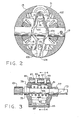
- FIG. 2 is a transverse cross section, taken generally along line 2-2 of FIG. 1, but on a smaller scale, and with all of the actuating.mechanism of the present invention in place.
- FIG. 3 is an axial cross section of the flyweight mechanism shown in FIG. 1, but on a larger scale than FIG. 1.
- FIG. 4 is a transverse cross section, taken on line 4-4 of FIG. 3, with the flyweight mechanism in the retracted position.
- FIG. 5 is a transverse cross section, similar to FIG. 4, with the flyweight mechanism in the extended position.
- FIG. 6 is a front elevation of the latch mechanism of the present invention, viewed in the same direction as FIG. 2.
- FIG. 7 is a side elevation of the latch mechanism, viewed in the same direction as in FIG. 1.
- FIG. 8 is a transverse cross section, also taken generally on line 2-2 of FIG. 1, but on a larger scale, and illustrating the inoperative position of the latch mechanism of the present invention.
- Referring now to the drawings, which are not intended to limit the present invention, FIG. 1 is an axial cross section of a differential gear mechanism made in accordance with the present invention. The differential gear mechanism includes a gear case comprising a lefthand casing section 11 and a
righthand casing section 13. Torque input to the gear mechanism is typically by means of an input gear (not shown), which may be bolted to thecasing section 13. - Disposed within the gear case is a differential gear set including a pair of planet pinions 15 (see FIG. 2), rotatably mounted on a
pinion shaft 17 which, in turn, is pinned to thecasing section 13. The planet pinions 15 comprise the input gears of the differential gear set and are in meshing engagement with a pair of side gears 19 and 21, which comprise the output gears of the differential gear set. The side gears 19 and 21 are splined to a pair ofaxle shafts casing sections 11 and 13 includeannular hub portions - During normal, straight-ahead operation of the vehicle, no differentiating action occurs between the left and
right axle shafts pinions 15 do not rotate relative to thepinion shaft 17, such that thecasing sections 11 and 13, thepinions 15, and side gears 19 and 21 and theaxle shafts shafts - Under certain operating conditions, such as when the vehicle is turning, or a slight loss of traction occurs, it is permissible for a certain amount of differentiating action to occur between the side gears 19 and 21, up to a predetermined level. Above that predetermined level of differentiating action (e.g., a difference of 100 rpm between the side gears), it is desirable to retard the relative rotation between the gear case and the side gears, to prevent excessive differentiating action.
- In order to retard differentiating action, the differential gear mechanism of the present invention is provided with a lockup means for locking up the differential gear set, and an actuating means for actuating the lockup means. In the subject embodiment, the lockup means comprises a clutch mechanism including a plurality of
clutch discs 31 and a plurality of clutch discs 33. Thecasing section 13 defines a plurality ofsemi-cylindrical openings 35. In the subject embodiment, there are four of theopenings 35, and disposed within each opening is asemi-cylindrical guide member 37 which helps to guide theclutch discs 31. Disposed within each of theguide members 37 is ahelical compression spring 39 which seats, at its opposite ends, against the lefthand and righthandclutch discs 31. The biasing force exerted by thesprings 39 must be sufficient to maintain theclutch discs 31 and 33 in the disengaged condition shown in FIG. 1, in the absence of other forces biasing the clutch discs together. - The lockup means further includes a cam mechanism, generally designated 41. As is well known to those skilled in the locking differential art, one function of the
cam mechanism 41 is to effect movement of the clutch pack from the disengaged condition shown in FIG. 1 to an engaged condition. It will become apparent from the subsequent description that, within the scope of the present invention, many different configurations and types of cam mechanism may be utilized. In the subject embodiment, thecam mechanism 41 is of the type illustrated and described in greater detail in copending European Patent Application No. (Jenkins & Co. Reference J. 147671. - The
cam mechanism 41 includes amain cam member 43 and anintermediate cam member 45. Themain cam member 43 defines a set ofexternal splines 47, and the clutch discs 33 define a set of internal splines such that the clutch discs 33 are splined to themain cam member 43 for rotation therewith. Theintermediate cam member 45 defines a set of straight,internal splines 51 which are in meshing engagement with a set of straight,external splines 53, formed about the outer periphery of theside gear 19. Thus, theintermediate cam member 45 is splined to theside gear 19 for rotation therewith, such that the forces transmitted from theintermediate cam member 45 to theside gear 19 are only rotational, with no substantial axial forces being transmitted to theside gear 19. - As is described in greater detail in the above-referenced copending application, the
intermediate cam member 45 defines a plurality of cam ramp surfaces 57, and themain cam member 43 defines a plurality of cam ramp surfaces 61. The relative rotational position of thecam members cam members side gear 19, at the same rotational speed. - As is also generally well known to those skilled in the art, movement of the clutch mechanism to the engaged condition may be accomplished by retarding rotation of the
main cam member 43, relative to theintermediate cam member 45. Such relative rotation between thecam members main cam member 43, to the right in FIG. 1. Such movement of thecam member 43 is in opposition to the biasing force of thesprings 39. Preferably, the lockup means utilized with the present invention is of the "self-energizing" type, i.e., the coefficient of friction of thediscs 31 and 33 and the cam angle (angle of ramp surfaces 57 and 61) are selected such that thecam member 43 would ramp and lock the clutch pack merely as a result of frictional drag between the discs, in the absence of thesprings 39. - However, under normal operating conditions, the
springs 39 prevent the discs from exerting sufficient drag on thecam member 43 to cause it to ramp. When the retarding torque on the main cam member is sufficient to overcome the force of thesprings 39, ramping and locking of the clutch pack will occur. The lockup means will remain actuated (with the differential gear set locked up) until the torque difference across the lockup means is substantially eliminated (e.g., both wheels turning at the same speed, with full traction), at which time the springs disengage the clutch pack. - In order to retard rotation of the
main cam member 43, relative to theintermediate cam member 45, the actuating means utilized with the present invention includes a retarding mechanism. In the subject embodiment, the retarding mechanism comprises a flyweight mechanism, generally designated 71. Within the scope of the invention, theflyweight mechanism 71 could have many different configurations, but in the subject embodiment, it is made in accordance with U. S. Pat. Nos. Re. 28,004 and 3,985,045, both of which are assigned to the assignee of the present invention. - As may best be seen by viewing FIGS. 3 and 4, in conjunction with FIG. 1, the
flyweight mechanism 71 includes amain shaft 73 on which is mounted a pair of coneclutch members endcaps clutch members compression spring 83. Received within cylindrical openings in theendcaps support shaft 85, and pivotally mounted on thesupport shaft 85 is a pair offlyweights support shaft 85 is aspacer 91, and disposed between theflyweights torsional spring member 93. As may best be seen in FIG. 4, thespring member 93 includes a pair ofend portions flyweights - Also mounted on the
main shaft 73 is an externally-toothed gear member 101 which is in engagement with a set of internal gear teeth 103 formed about the inner periphery of themain cam member 43, as is described in greater detail in the above-referenced copending application. - As may best be seen in FIGS. I and 2, a
bracket member 105 is rigidly attached to thecasing section 13 by fourmachine screws 107. Thebracket member 105 defines a generally circularcentral opening 109, and a straight-sided opening 110, disposed above theopening 109 and contiguous therewith. The function of theopening 110 will be described subsequently. Thebracket member 105 further defines a circular opening which receives and supports thecone clutch 75 andmain shaft 73 of theflyweight mechanism 71, with the opposite end of themain shaft 73 being rotatably supported by thecasing section 13. Therefore, theflyweight mechanism 71 is mounted for rotation about its own axis. - During operation, if differentiating action begins to occur between the
axle shafts side gear 19 and the gear case, thecam members gear member 101 and gear teeth 103, theflyweight mechanism 71 will begin to rotate about its own axis at a rotational speed which is a function of the level of the differentiating action. As the speed of rotation of theflyweight mechanism 71 increases, centrifugal force causes theflyweights spring 93. - In order to retard rotation of the
main cam member 43, relative to theintermediate cam member 45, the actuating means of the present invention includes a stop means (or latch means), operable to prevent rotation of theflyweight mechanism 71, when a predetermined level of differentiating action occurs. When rotation of theflyweight mechanism 71 is prevented, the additional retarding force thereby applied to themain cam member 43 is sufficient to overcome the biasing force of thesprings 39, resulting in lockup of the clutch pack. - Referring now primarily to FIGS. 6 and 7, in conjunction with FIG. 1, the stop means or latch means of the present invention comprises a novel latch mechanism, generally designated 111. In the subject embodiment, and by way of example only, the latch mechanism 111 includes a one-piece, stamped
frame member 113, including anarcuate latch member 115 which, as may be seen in FIG. 1, extends toward thebracket member 105. Thelatch member 115 includes aguide tab 116 which is movably disposed (up and down in FIGS. 1 and 2) within theopening 110, to help maintain orientation of the latch mechanism 111 relative to thebracket member 105, during operating conditions which will be described subsequently. The latch mechanism 111 further includes aweighted member 117 which is attached to theframe member 113 by means of arivet 119. Theweighted member 117 defines acylindrical bore 121 within which is seated a compression spring 123 (FIGS. 1 and 8). The other end of thespring 123 is seated against a lower, L--shapedportion 124 of thebracket member 105. Referring now to FIGS. 4 and 5, in conjunction with FIGS. 6 and 7, thelatch member 115 includes a pair of oppositely disposed latch surfaces 125 and 127 which are effective to prevent rotation of thelatch mechanism 71 in a manner to be described subsequently. - Under normal operating conditions, with little or no differentiating action occurring, the
torsion spring 93 is effective to maintain theflyweights compression spring 123 biases the latch mechanism 111 toward theflyweight mechanism 71, such that thelatch member 115 is in the position shown in FIGS. 3 and 4, either touching the end caps 79 and 81 or being closely spaced apart therefrom. - When the level of differentiating action exceeds a predetermined limit, centrifugal force causes the
flyweights spring 93 and move outwardly to the position shown in FIG. 5. Theflyweights stop surfaces latch mechanism 71, which in turn depends upon the direction of relative rotation between the side gears 19 and 21, one of the stop surfaces will engage one of the latch surfaces, preventing further rotation of theflyweight mechanism 71. For example, with theflyweight mechanism 71 rotating clockwise as shown in FIG. 5, thestop surface 131 defined by theflyweight 89 engages thelatch surface 127 on thelatch member 115. If thelatch mechanism 71 were rotating counterclockwise, with the stop surfaces in the extended position, thestop surface 129 defined by theflyweight 87 would engage thelatch surface 125. - As is well known to those skilled in the locking differential art, it is considered desirable that the stop means, such as the latch mechanism 111 of the present invention, be operable to prevent rotation of the
flyweight mechanism 71 only up to a predetermined rotational speed of the differential gear mechanism, corresponding to a predetermined vehicle speed. For example, at vehicle speeds below about 20 mph, the latch mechanism 111 will operate as described above. However, at vehicle speeds of about 20 mph or greater, it is generally considered unnecessary, or even undesirable, by those skilled in the art to lockup the differential gear set, regardless of the level of differentiating action. Accordingly, the latch mechanism 111 of the present invention is effective to be deactivated or "locked out" above a predetermined rotational speed of the differential gear mechanism. - Referring now primarily to FIG. 8, the operation of the present invention above the predetermined rotational speed is illustrated. With the occurrence of a sufficient level of differentiating action, the
flyweights weighted member 117 and causes movement of the entire latch mechanism, in opposition to the biasing force of thespring 123. As illuatrated in FIG. 8, because theweighted member 117 is oppositely disposed from thelatch member 115, about the axis of rotation of the mechanism, movement of theweighted member 117 outwardly, as a result of centrifugal force, causes movement of thelatch member 115 inwardly. An important feature of the present invention, also illustrated in FIG. 8, is that the movement of the latch mechanism 111 is along a path which is straight and which is generally diametrally-oriented, rather than being pivotal. As a result, substantially the entire mass of theweighted member 117 is directly effected by centrifugal force. - Referring still to FIG. 8, it may be seen that the movement of the latch mechanism 111, as a result of centrifugal force acting on the
weighted member 117, moves thelatch member 115 from its operative position (shown by a dotted line in FIG. 8, corresponding to the FIG. 5 position), to an inoperative position. In the operative position illustrated in FIG. 8, rotation of theflyweight mechanism 71 does not cause engagement of either of the stop surfaces 129 or 131 by itsrespective latch surface
Claims (12)
Applications Claiming Priority (2)
| Application Number | Priority Date | Filing Date | Title |
|---|---|---|---|
| US22662 | 1979-03-22 | ||
| US06/022,662 US4265143A (en) | 1979-03-22 | 1979-03-22 | Latch mechanism for locking differential |
Publications (2)
| Publication Number | Publication Date |
|---|---|
| EP0017392A1 true EP0017392A1 (en) | 1980-10-15 |
| EP0017392B1 EP0017392B1 (en) | 1983-06-29 |
Family
ID=21810764
Family Applications (1)
| Application Number | Title | Priority Date | Filing Date |
|---|---|---|---|
| EP80300853A Expired EP0017392B1 (en) | 1979-03-22 | 1980-03-19 | Latch mechanism for locking differential |
Country Status (4)
| Country | Link |
|---|---|
| US (1) | US4265143A (en) |
| EP (1) | EP0017392B1 (en) |
| JP (1) | JPS55129642A (en) |
| DE (1) | DE3063944D1 (en) |
Cited By (1)
| Publication number | Priority date | Publication date | Assignee | Title |
|---|---|---|---|---|
| EP1156233A2 (en) * | 2000-05-15 | 2001-11-21 | Eaton Corporation | Compact locking differential |
Families Citing this family (10)
| Publication number | Priority date | Publication date | Assignee | Title |
|---|---|---|---|---|
| US4389909A (en) * | 1981-05-26 | 1983-06-28 | Eaton Corporation | Cam mechanism for limited slip or locking differential |
| US4554845A (en) * | 1982-10-01 | 1985-11-26 | Goscenski Jr Edward J | Positive drive and secondary clutch means therefor |
| JPS6173858U (en) * | 1984-10-19 | 1986-05-19 | ||
| US7438661B2 (en) * | 2006-02-15 | 2008-10-21 | Eaton Corporation | Mechanical locking differential lockout mechanism |
| US7399248B2 (en) * | 2006-05-22 | 2008-07-15 | Ford Motor Company | Moving coil electronic locking differential |
| US7602271B2 (en) * | 2006-08-21 | 2009-10-13 | American Axle & Manufacturing, Inc. | Electronically actuated apparatus using solenoid actuator with integrated sensor |
| US10364850B2 (en) * | 2012-10-23 | 2019-07-30 | Ford Global Technologies, Llc | Clutch mechanism |
| US9587692B2 (en) | 2015-04-01 | 2017-03-07 | Akebono Brake Industry Co., Ltd | Differential for a parking brake assembly |
| US10066722B2 (en) * | 2017-01-05 | 2018-09-04 | GM Global Technology Operations LLC | Limited slip differentials with centrifugal spring mass actuator for vehicle powertrains |
| US11339842B2 (en) | 2019-03-26 | 2022-05-24 | Akebono Brake Industry Co., Ltd. | Brake system with torque distributing assembly |
Citations (5)
| Publication number | Priority date | Publication date | Assignee | Title |
|---|---|---|---|---|
| US1522739A (en) * | 1923-04-13 | 1925-01-13 | Henry C Mohr | Fencepost |
| US3517573A (en) * | 1968-05-08 | 1970-06-30 | Eaton Yale & Towne | Centrifugally actuated locking differential |
| USRE28004E (en) * | 1973-06-07 | 1974-05-07 | Centrifugal actuator for limited slip differential | |
| US3938408A (en) * | 1973-06-28 | 1976-02-17 | Eaton Corporation | Differential drive mechanism |
| US3985045A (en) * | 1975-01-17 | 1976-10-12 | Eaton Corporation | Locking device for a differential drive mechanism |
Family Cites Families (7)
| Publication number | Priority date | Publication date | Assignee | Title |
|---|---|---|---|---|
| US2387031A (en) * | 1944-03-04 | 1945-10-16 | Letourneau Inc | Self-locking differential |
| DE1063906B (en) * | 1958-01-03 | 1959-08-20 | Wilhelm Bors | Trailer axle drive |
| US3606803A (en) * | 1969-09-17 | 1971-09-21 | Eaton Yale & Towne | Centrifugal actuator for limited slip differential |
| US3831462A (en) * | 1972-03-16 | 1974-08-27 | Eaton Corp | Limited slip differential |
| US3818781A (en) * | 1973-01-02 | 1974-06-25 | Eaton Corp | Differential gear mechanism |
| US3893351A (en) * | 1973-06-19 | 1975-07-08 | Eaton Corp | Limited slip differential drive mechanism |
| US3845672A (en) * | 1973-11-08 | 1974-11-05 | Eaton Corp | Differential drive mechanism |
-
1979
- 1979-03-22 US US06/022,662 patent/US4265143A/en not_active Expired - Lifetime
-
1980
- 1980-03-19 EP EP80300853A patent/EP0017392B1/en not_active Expired
- 1980-03-19 DE DE8080300853T patent/DE3063944D1/en not_active Expired
- 1980-03-22 JP JP3679880A patent/JPS55129642A/en active Granted
Patent Citations (5)
| Publication number | Priority date | Publication date | Assignee | Title |
|---|---|---|---|---|
| US1522739A (en) * | 1923-04-13 | 1925-01-13 | Henry C Mohr | Fencepost |
| US3517573A (en) * | 1968-05-08 | 1970-06-30 | Eaton Yale & Towne | Centrifugally actuated locking differential |
| USRE28004E (en) * | 1973-06-07 | 1974-05-07 | Centrifugal actuator for limited slip differential | |
| US3938408A (en) * | 1973-06-28 | 1976-02-17 | Eaton Corporation | Differential drive mechanism |
| US3985045A (en) * | 1975-01-17 | 1976-10-12 | Eaton Corporation | Locking device for a differential drive mechanism |
Cited By (2)
| Publication number | Priority date | Publication date | Assignee | Title |
|---|---|---|---|---|
| EP1156233A2 (en) * | 2000-05-15 | 2001-11-21 | Eaton Corporation | Compact locking differential |
| EP1156233A3 (en) * | 2000-05-15 | 2006-08-16 | Eaton Corporation | Compact locking differential |
Also Published As
| Publication number | Publication date |
|---|---|
| US4265143A (en) | 1981-05-05 |
| DE3063944D1 (en) | 1983-08-04 |
| JPS6238577B2 (en) | 1987-08-18 |
| JPS55129642A (en) | 1980-10-07 |
| EP0017392B1 (en) | 1983-06-29 |
Similar Documents
| Publication | Publication Date | Title |
|---|---|---|
| EP1156233B1 (en) | Compact locking differential | |
| US5007886A (en) | Limited slip differential | |
| EP0017392B1 (en) | Latch mechanism for locking differential | |
| EP1984653B1 (en) | Mechanical locking differential lockout mechanism | |
| US4389909A (en) | Cam mechanism for limited slip or locking differential | |
| US3831462A (en) | Limited slip differential | |
| US3886813A (en) | Differential | |
| KR101836789B1 (en) | Reaction bolck mounted lock-out mechanism and differential having such a reaction block | |
| US3517573A (en) | Centrifugally actuated locking differential | |
| CA2763433A1 (en) | Locking differential side gear to friction disc unloading | |
| US3818781A (en) | Differential gear mechanism | |
| EP2057391A1 (en) | Cam gear for mechanical locking differential | |
| EP0016641B1 (en) | Locking differential | |
| US3811341A (en) | Differential gear mechanism | |
| US5310382A (en) | Transmission device with a controlled viscous coupler, in particular for a motor vehicle | |
| US4206662A (en) | Locking differential for a four-wheel drive system having a coast-release mechanism | |
| US11592094B2 (en) | Differential having an overrunning clutch with inertial compensation tuning | |
| EP0263578A1 (en) | Limited slip differential | |
| WO2022251198A1 (en) | Differential having an overrunning clutch with inertial compensation tuning | |
| JPH05223133A (en) | Driving force transmission | |
| KR20000011401A (en) | Center differential device |
Legal Events
| Date | Code | Title | Description |
|---|---|---|---|
| PUAI | Public reference made under article 153(3) epc to a published international application that has entered the european phase |
Free format text: ORIGINAL CODE: 0009012 |
|
| AK | Designated contracting states |
Designated state(s): DE FR GB IT |
|
| 17P | Request for examination filed |
Effective date: 19810303 |
|
| ITF | It: translation for a ep patent filed |
Owner name: ING. C. GREGORJ S.P.A. |
|
| GRAA | (expected) grant |
Free format text: ORIGINAL CODE: 0009210 |
|
| AK | Designated contracting states |
Designated state(s): DE FR GB IT |
|
| REF | Corresponds to: |
Ref document number: 3063944 Country of ref document: DE Date of ref document: 19830804 |
|
| ET | Fr: translation filed | ||
| PLBE | No opposition filed within time limit |
Free format text: ORIGINAL CODE: 0009261 |
|
| STAA | Information on the status of an ep patent application or granted ep patent |
Free format text: STATUS: NO OPPOSITION FILED WITHIN TIME LIMIT |
|
| 26N | No opposition filed | ||
| PGFP | Annual fee paid to national office [announced via postgrant information from national office to epo] |
Ref country code: FR Payment date: 19891210 Year of fee payment: 11 |
|
| PGFP | Annual fee paid to national office [announced via postgrant information from national office to epo] |
Ref country code: DE Payment date: 19891212 Year of fee payment: 11 |
|
| PGFP | Annual fee paid to national office [announced via postgrant information from national office to epo] |
Ref country code: GB Payment date: 19891231 Year of fee payment: 11 |
|
| ITTA | It: last paid annual fee | ||
| PG25 | Lapsed in a contracting state [announced via postgrant information from national office to epo] |
Ref country code: GB Effective date: 19910319 |
|
| GBPC | Gb: european patent ceased through non-payment of renewal fee | ||
| PG25 | Lapsed in a contracting state [announced via postgrant information from national office to epo] |
Ref country code: FR Effective date: 19911129 |
|
| PG25 | Lapsed in a contracting state [announced via postgrant information from national office to epo] |
Ref country code: DE Effective date: 19920101 |
|
| REG | Reference to a national code |
Ref country code: FR Ref legal event code: ST |