EP0017082A1 - Dispositif thermoélectrique à transfert de chaleur entre un premier fluide gazeux et un deuxième fluide - Google Patents
Dispositif thermoélectrique à transfert de chaleur entre un premier fluide gazeux et un deuxième fluide Download PDFInfo
- Publication number
- EP0017082A1 EP0017082A1 EP80101434A EP80101434A EP0017082A1 EP 0017082 A1 EP0017082 A1 EP 0017082A1 EP 80101434 A EP80101434 A EP 80101434A EP 80101434 A EP80101434 A EP 80101434A EP 0017082 A1 EP0017082 A1 EP 0017082A1
- Authority
- EP
- European Patent Office
- Prior art keywords
- cell
- type
- heat
- thermal
- stack
- Prior art date
- Legal status (The legal status is an assumption and is not a legal conclusion. Google has not performed a legal analysis and makes no representation as to the accuracy of the status listed.)
- Withdrawn
Links
- 239000012530 fluid Substances 0.000 title claims description 34
- 239000002470 thermal conductor Substances 0.000 claims abstract description 36
- 239000007787 solid Substances 0.000 claims description 5
- 239000000463 material Substances 0.000 claims description 4
- 238000010438 heat treatment Methods 0.000 abstract description 5
- XLYOFNOQVPJJNP-UHFFFAOYSA-N water Substances O XLYOFNOQVPJJNP-UHFFFAOYSA-N 0.000 description 23
- 230000006835 compression Effects 0.000 description 9
- 238000007906 compression Methods 0.000 description 9
- 239000004020 conductor Substances 0.000 description 8
- 206010017076 Fracture Diseases 0.000 description 4
- 229910052751 metal Inorganic materials 0.000 description 4
- 239000002184 metal Substances 0.000 description 4
- 238000003466 welding Methods 0.000 description 4
- 208000010392 Bone Fractures Diseases 0.000 description 3
- 238000004519 manufacturing process Methods 0.000 description 3
- RYGMFSIKBFXOCR-UHFFFAOYSA-N Copper Chemical compound [Cu] RYGMFSIKBFXOCR-UHFFFAOYSA-N 0.000 description 2
- 241000287107 Passer Species 0.000 description 2
- 238000004378 air conditioning Methods 0.000 description 2
- 229910052782 aluminium Inorganic materials 0.000 description 2
- XAGFODPZIPBFFR-UHFFFAOYSA-N aluminium Chemical compound [Al] XAGFODPZIPBFFR-UHFFFAOYSA-N 0.000 description 2
- 230000008602 contraction Effects 0.000 description 2
- 238000001816 cooling Methods 0.000 description 2
- 229910052802 copper Inorganic materials 0.000 description 2
- 239000010949 copper Substances 0.000 description 2
- 238000005452 bending Methods 0.000 description 1
- 229910052797 bismuth Inorganic materials 0.000 description 1
- JCXGWMGPZLAOME-UHFFFAOYSA-N bismuth atom Chemical compound [Bi] JCXGWMGPZLAOME-UHFFFAOYSA-N 0.000 description 1
- 238000010276 construction Methods 0.000 description 1
- 230000010339 dilation Effects 0.000 description 1
- 238000006073 displacement reaction Methods 0.000 description 1
- 238000009826 distribution Methods 0.000 description 1
- 230000005489 elastic deformation Effects 0.000 description 1
- 239000006260 foam Substances 0.000 description 1
- 239000012212 insulator Substances 0.000 description 1
- 238000005304 joining Methods 0.000 description 1
- 230000007774 longterm Effects 0.000 description 1
- 239000000203 mixture Substances 0.000 description 1
- 229920000915 polyvinyl chloride Polymers 0.000 description 1
- 239000004800 polyvinyl chloride Substances 0.000 description 1
- 238000003825 pressing Methods 0.000 description 1
- 238000007789 sealing Methods 0.000 description 1
- 229910001220 stainless steel Inorganic materials 0.000 description 1
- 239000010935 stainless steel Substances 0.000 description 1
- XSOKHXFFCGXDJZ-UHFFFAOYSA-N telluride(2-) Chemical compound [Te-2] XSOKHXFFCGXDJZ-UHFFFAOYSA-N 0.000 description 1
Images


Classifications
-
- F—MECHANICAL ENGINEERING; LIGHTING; HEATING; WEAPONS; BLASTING
- F25—REFRIGERATION OR COOLING; COMBINED HEATING AND REFRIGERATION SYSTEMS; HEAT PUMP SYSTEMS; MANUFACTURE OR STORAGE OF ICE; LIQUEFACTION SOLIDIFICATION OF GASES
- F25B—REFRIGERATION MACHINES, PLANTS OR SYSTEMS; COMBINED HEATING AND REFRIGERATION SYSTEMS; HEAT PUMP SYSTEMS
- F25B21/00—Machines, plants or systems, using electric or magnetic effects
- F25B21/02—Machines, plants or systems, using electric or magnetic effects using Peltier effect; using Nernst-Ettinghausen effect
-
- H—ELECTRICITY
- H10—SEMICONDUCTOR DEVICES; ELECTRIC SOLID-STATE DEVICES NOT OTHERWISE PROVIDED FOR
- H10N—ELECTRIC SOLID-STATE DEVICES NOT OTHERWISE PROVIDED FOR
- H10N10/00—Thermoelectric devices comprising a junction of dissimilar materials, i.e. devices exhibiting Seebeck or Peltier effects
-
- H—ELECTRICITY
- H10—SEMICONDUCTOR DEVICES; ELECTRIC SOLID-STATE DEVICES NOT OTHERWISE PROVIDED FOR
- H10N—ELECTRIC SOLID-STATE DEVICES NOT OTHERWISE PROVIDED FOR
- H10N10/00—Thermoelectric devices comprising a junction of dissimilar materials, i.e. devices exhibiting Seebeck or Peltier effects
- H10N10/10—Thermoelectric devices comprising a junction of dissimilar materials, i.e. devices exhibiting Seebeck or Peltier effects operating with only the Peltier or Seebeck effects
- H10N10/13—Thermoelectric devices comprising a junction of dissimilar materials, i.e. devices exhibiting Seebeck or Peltier effects operating with only the Peltier or Seebeck effects characterised by the heat-exchanging means at the junction
-
- H—ELECTRICITY
- H10—SEMICONDUCTOR DEVICES; ELECTRIC SOLID-STATE DEVICES NOT OTHERWISE PROVIDED FOR
- H10N—ELECTRIC SOLID-STATE DEVICES NOT OTHERWISE PROVIDED FOR
- H10N10/00—Thermoelectric devices comprising a junction of dissimilar materials, i.e. devices exhibiting Seebeck or Peltier effects
- H10N10/10—Thermoelectric devices comprising a junction of dissimilar materials, i.e. devices exhibiting Seebeck or Peltier effects operating with only the Peltier or Seebeck effects
- H10N10/17—Thermoelectric devices comprising a junction of dissimilar materials, i.e. devices exhibiting Seebeck or Peltier effects operating with only the Peltier or Seebeck effects characterised by the structure or configuration of the cell or thermocouple forming the device
Definitions
- thermoelements thermoelectric elements mounted between thermal conductors associated with hot exchangers traversed by a hot fluid and with exchangers cold crossed by a cold fluid.
- the heat is brought to the thermoelements and to the thermal conductors by the cold exchangers and transferred to the hot exchangers.
- thermoelements being supplied with direct electric current to maintain a temperature difference between the thermal conductors.
- a device called a "heat pump”
- heat pump can also be used for air conditioning purposes by heating or cooling a fluid from the ambient atmosphere.
- thermoelectric devices For the construction of thermoelectric devices, it has already been proposed to make them comprise batteries of hot and cold exchangers electrically conductive and separated by thermoelements alternately of types P and N, the electric current flowing in the direction of stacking, this sense being vertical for example.
- These vertical stacks are arranged side by side so as to constitute a set of parallelepipedal shape in which the plates constituting the thermoelements are arranged in a succession of horizontal planes and the exchangers in the intermediate horizontal planes.
- Each exchanger is traversed by one of the fluids in a horizontal direction which is not the same depending on whether it is the cold fluid or the hot fluid.
- the mechanical structure is designed to reconcile the sealing requirements concerning the fluid circuits with the presence of differential thermal expansions.
- the realization of this structure is made particularly delicate by the fact that the known thermoelements based on bismuth telluride are extremely fragile.
- a first drawback is due to the need to pass a sufficient gas flow through the gas exchangers, that is to say through the heat exchangers supplying or taking heat to the gas. This necessity leads to giving these exchangers large dimensions which cause considerable bulk of the device.
- a second drawback stems from the fact that the gas circuit, when it must pass through the successive gas exchangers of the same stack, is necessarily a sinuous path which causes high pressure drops. Bulky and noisy fans must therefore be provided to circulate the gas.
- each stage of the stack comprises a P type thermoelement by example, a hot exchanger for example, an N type thermoelement and a cold exchanger, the current flowing in series through these four elements of each stage and all the stages of the stack.
- the stack is kept in permanent vertical compression thanks to a spring pressing on one of its ends, this to avoid the appearance of mechanical tensions in thermoelements.
- This device allows heat transfer between two cold and hot air ducts arranged on the right and left of the stack, respectively.
- Each exchanger comprises a part arranged in the stack clamped between two thermoelements, and traversed by the electric current, and a part arranged outside the stack, in the corresponding air duct so as to ensure heat exchange with the 'air. Heat is therefore transferred laterally between the stack and each duct.
- This device having a hot side and an opposite cold side, has the drawback of undergoing asymmetrical thermal dilations or contractions which tend to create a curvature of the stack, and lead in the long term to fractures of the thermoelements.
- the object of the present invention is to produce a thermoelectric device for heat transfer between a first gaseous fluid and a second fluid, making it possible to act on a large gas flow rate with a reduced bulk of the device and low pressure drops in the gas circuit, while avoiding any asymmetrical thermal expansion.
- This gas pipe is advantageously parallel to the cell.
- the device has several batteries.
- several gas conduits can conduct the gas perpendicular to the piles of the same row, next to the row and in its direction.
- the first embodiment of the invention operates thermally between a first fluid which is air and a second fluid which is water.
- Air constitutes the hot source and is heated by cooling the cold source constituted by water, that is to say that the device constitutes a water-air heat pump.
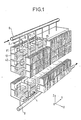
- This pump has a row of batteries such as P1, P2, P3 etc. constituted by a stack of thermoelements and thermal conductors forming part of heat exchangers of a first type, air, and of a second type, water.
- Each stack rises in a vertical direction OZ, the row extending in a horizontal direction OY which will be considered for example as going from front to back.
- each pile has the shape of a vertical prism with square section, two sides of the square being prallel to OY and two others to a horizontal direction OX perpendicular to OY which we will consider for example as going from right to left.
- each stack has four vertical faces: front, right, rear and left.
- the elements which make up the stack do not all have the same horizontal dimensions, those of the thermoelements being notably much smaller than those of the heat exchangers, the axis of the stack being a vertical line passing through the centers of all the thermoelements of the stack.
- the air heat exchangers are the widest. They each have a part which is located between the thermoelements. It is this part inside the battery which constitutes a thermal conductor of the first type previously mentioned.
- Each stage of the stack comprises a heat conductor of the first type forming part of an air heat exchanger, a thermoelement of a first type P or N, a heat conductor of the second type constituting a water heat exchanger and a thermoelement of a second type opposite to the first.
- Three circuits are connected to these batteries, namely an electrical circuit, and a first and a second fluid circuit which are an air circuit and a water circuit.
- the electric circuit is intended to make the thermoelements cross by an electric current directed according to OZ, for example for the batteries of even rank such as P2, and according to ZO for the batteries of odd rank such as P1 and P3.
- These batteries are successively supplied in series from two terminals such as 2 each disposed at a suitable end of one of the two batteries located at the two ends of the row.
- Such a series connection makes it possible to obtain an acceptable impedance of the heat pump despite the low impedance of each cell.
- the connections between batteries are made by bars such as 4 arranged alternately in the lower part and in the upper part.
- the set of air circuits in the row of cells is essentially constituted by two vertical air ducts such as 28 (see Figure 4) forming two symmetrical air layers to the left and right of the row. It would obviously be possible, but the folding less advantageous, that there is only one conduit per pile, on the left or on the right, or that the conduits corresponding to the various piles are completely separated from each other.
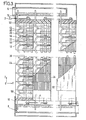
- Each conduit such as 28 is mainly limited by two vertical walls parallel to the YOZ plane, an internal wall 34 which is not homogeneous, the composition of which will be described below, and an external wall 32, for example an insulating wall. It can also be limited at the front and rear by two plates parallel to the XOZ plane and not shown.
- the entire volume of the duct is occupied by a set of heat exchange blocks such as 36 constituted by vertical fins having a large surface area for heat exchange with air, as known.
- Each of these blocks is part of a heat exchanger comprising an air thermal conductor of the cell.
- These blocks follow one another vertically opposite a pile, and horizontally back and forth, opposite the successive piles of the row. They are made of a metal that is a good thermal conductor such as aluminum. They are fixed to the internal wall 34 by welding.
- the wall 34 is constituted by vertical lateral cheeks, such as 38 forming the raised ends of horizontal arms such as 40 arranged to the right and to the left of each air thermal conductor such as 54 (see Figures 2 and 4), in good contact thermal. More particularly the latter has the shape of a vertical solid cylinder passing through the center of a horizontal plate 42 and welded to the latter and the two sides of this plate form the two arms 40 to the right and to the left.
- These cheeks 38 have the shape of rectangular plates arranged in planes parallel to YOZ, and having dimensions such that they occupy substantially the entire surface of the wall 32. To avoid electrical short circuits of thin insulating sheets such as 44 are arranged between the edges of the adjacent plates formed by these cheeks.
- tie rods around each stack at the four corners of its square section. They are threaded at their ends so as to allow, with the aid of nuts 48 and insulating support plates 50, to provide the assembly with effective compression which is essentially supported by the cheeks 38, ensures the rigidity of the 'the entire stack, and keeps the thermoelements in compression.
- the assembly of the plate 42 with the two arms 40 to the right and to the left, and of the two cheeks 38 at the ends of these arms constitutes a single piece 52 made for example of nickel-plated aluminum.
- This part can be considered as formed by three plates which are two vertical plates parallel to the plane YOZ, that is to say the two cheeks 38, and the horizontal base plate 42 joining the two cheeks. It presents front view, the shape of a U, but could also present that of a lying I.
- the cheeks 38 extend rearwards beyond the base plate 42 and provide between them a free space partially occupied by the connecting sections of a water conduit which will be described later.
- Such a part has two functions: a first function is that it constitutes a stage of a holding column formed by the stack of similar parts, and cooperating with the tie rods 30 to produce a rigid mechanical structure, solid and easy to assemble , each stage of this column corresponding to one stage of the stack.
- the second function is to cooperate with the heat exchange blocks 26 to form an air heat exchanger on each stage of the stack.
- thermoelements The contact between the thermoelements and the part 52 is ensured by the solid cylinders 54 of the same material as the latter and arranged in the holes drilled in the center of the plates 42 projecting above and below.
- the thickness of the plate 42 is for example 6 mm, its width along OY 50 mm, its length along OX 63 mm, the cheeks 38 having a thickness of 2 mm, a height of 24 mm, and a width of 50 mm.
- the water circuit includes an inlet manifold 6 bringing lukewarm water (15 ° C) and an outlet manifold 8, supplying cooled water (O O C), these two collectors being arranged parallel to OY above and below the row of batteries.
- the cells are supplied in parallel between these two collectors, each by a conduit such as 10 which passes in series through all the thermal conductors for water in the cell.
- the lower end of this duct is situated substantially vertically from its upper end, but it has a complex sinuous shape between the two, constituted by an alternating succession of connecting sections such as 12 and of heat exchange sections such as 14 (see figure 2).
- Each heat exchange section is arranged in a horizontal plane, in a water thermal conductor.
- connection section has the shape of a U in a plane parallel to YOZ, the branches of the U being parallel to OY, one above the other below, in continuity with the ends of the exchange sections thermal passing through two thermal water conductors in succession in the stack. All the heat exchange sections overlap.
- the connecting sections alternately overlap in two planes parallel to YOZ, one on the right, the other on the left.
- the heat exchange sections must have a low thermal resistance when crossing their wall.
- the connecting sections must have a strong longitudinal electrical resistance and could in some cases be made of a material insulator such as polyvinyl chloride.
- the heat exchange sections pass through the water thermal conductors, such as 16 previously called thermal conductors of the second type, and cooperate with them to form water heat exchangers, that is to say that these thermal conductors, which form part of the stack, directly transmit heat between water and the thermoelements of the stack.
- thermal conductors which form part of the stack
- They could be formed in various known ways, for example in the form of solid blocks of copper crossed by the heat exchange sections of the tube 10. It has however been found preferable to constitute them in an inexpensive manner, suitable for give them some elasticity in the direction of the pile.
- Such elasticity makes it possible to easily maintain the stack in compression over the entire length despite small longitudinal displacements which are imposed on it from place to place by a rigid holding structure which is external to it and which undergoes thermal expansions and contractions, this structure being here constituted by the previously mentioned holding column and formed by the stack of parts 52 cooperating with the tie rods 30.
- Such permanent compression has the advantage of reducing the risk of fracture of the thermoelements, and, if such a fracture occurs however, maintain acceptable electrical contact at the location of the fracture.
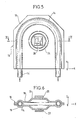
- Each water heat exchanger consists of two sheets of copper (or of another metal which is a good thermal conductor) welded to each other on part of their edges and arranged symmetrically on either side of the plane d 'a heat exchange section 14 to which they are also welded, so as in particular to improve the thermal contact.
- each heat exchange section such as U-shaped 14 makes a U-turn around the compressed area of the stack in which the thermoelements such as 20 and 22 are in the form of platelets. horizontal squares. These plates are arranged substantially vertically from the center of a semicircle constituting the base of the U.
- the sheet 18 covers the U and projects laterally to the right and left beyond the branches and rearward beyond from the base so that the U is completely located inside the sheet.
- the sheet 18 is stamped so that its part which projects beyond the U is in contact with the sheet 19, in the median horizontal plane of the heat exchange section 14. It is in this projecting part that these two sheets are welded. one to the other.
- thermoelement 20 There is no rimpedement or welding of the two sheets on the front edge and in the entire area between the two branches of the U.
- the sheet 18 is stamped so as to still move away from the sheet 19 and to form a projection central 24 upwards in the zone on which the thermoelement 20 is welded. It is the space between the two sheets under the central projection and up to the heat exchange section 14 which, by bending of the sheet, gives at the heat exchanger a certain longitudinal elasticity, that is to say in the direction OZ, because the mechanical connection between the thermoelements 20 and 22 is made by means of the sheets 18 and 19 which are only joined by their edges and by the heat exchange section 14.
- the following dimensions can be given for the water heat exchanger:
- the cylinders 54 are welded to the plates 42, and the thermos elements 20, 22 to these cylinders and to the central projections 24 of the water exchangers.
- the compression maintaining column is then put by tightening the nuts 48.
- the interior space between the walls 34 is filled with an insulating foam polymerized in place and intended to avoid thermal short-circuits.
- the water-air heat pump thus produced can advantageously be used for heating the air in a living room from a water circuit. It can be combined with various conventional heating or air conditioning devices.
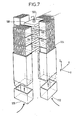
- FIG. 7 An air-air heat pump shown very schematically in FIG. 7.
- This consists of a vertical stack (direction OZ) supplied electrically by means of terminals such as 100.
- Each stage of this stack comprises an air thermal conductor of a first type such as 102 for example hot, a P type thermoelement such as 104, a thermal air conductor such as 106 of a second type identical to the first, for example cold, and an N type thermoelement such as 108.
- Each thermal conductor is part of an air heat exchanger similar to those of the first embodiment of the invention and which transmits heat; outside the stack, in both directions in a direction OX (and XO) for hot thermal conductors and in both directions in a perpendicular direction OY (and YO) for cold conductors.
- OX and XO
- OY and YO
- Four hot 110 and cold 112 vertical air ducts are arranged along the four faces of the stack and contain heat exchange blocks with vertical fins such as 114 identical to those of the first embodiment of the invention.
- the hot ducts are arranged for example in front and behind the stack, and the cold ones on the left and on the right.
Landscapes
- Engineering & Computer Science (AREA)
- Physics & Mathematics (AREA)
- Mechanical Engineering (AREA)
- Thermal Sciences (AREA)
- General Engineering & Computer Science (AREA)
- Heat-Exchange Devices With Radiators And Conduit Assemblies (AREA)
Applications Claiming Priority (2)
| Application Number | Priority Date | Filing Date | Title |
|---|---|---|---|
| FR7907517 | 1979-03-26 | ||
| FR7907517A FR2452795A1 (fr) | 1979-03-26 | 1979-03-26 | Dispositif thermoelectrique a transfert de chaleur entre un premier fluide gazeux et un deuxieme fluide |
Publications (1)
| Publication Number | Publication Date |
|---|---|
| EP0017082A1 true EP0017082A1 (fr) | 1980-10-15 |
Family
ID=9223558
Family Applications (1)
| Application Number | Title | Priority Date | Filing Date |
|---|---|---|---|
| EP80101434A Withdrawn EP0017082A1 (fr) | 1979-03-26 | 1980-03-19 | Dispositif thermoélectrique à transfert de chaleur entre un premier fluide gazeux et un deuxième fluide |
Country Status (3)
| Country | Link |
|---|---|
| US (1) | US4306426A (OSRAM) |
| EP (1) | EP0017082A1 (OSRAM) |
| FR (1) | FR2452795A1 (OSRAM) |
Cited By (3)
| Publication number | Priority date | Publication date | Assignee | Title |
|---|---|---|---|---|
| FR2540978A1 (fr) * | 1983-02-11 | 1984-08-17 | Realisa Aerothermiques Et | Dispositif de climatisation et engin de transport muni d'un tel dispositif |
| DE3624844A1 (de) * | 1986-07-23 | 1988-01-28 | Josef Schucker | Temperiergeraet fuer fluessige klebstoffe |
| CN112041631A (zh) * | 2018-06-20 | 2020-12-04 | 柯勒米拉有限公司 | 能量回收 |
Families Citing this family (17)
| Publication number | Priority date | Publication date | Assignee | Title |
|---|---|---|---|---|
| DE3164237D1 (en) * | 1980-12-23 | 1984-07-19 | Air Ind | Thermo-electrical plants |
| FR2514113A1 (fr) * | 1981-10-07 | 1983-04-08 | Comp Generale Electricite | Pompe a chaleur thermoelectrique air-air |
| FR2542855B1 (fr) * | 1983-03-17 | 1985-06-28 | France Etat Armement | Installation thermoelectrique |
| US4734139A (en) * | 1986-01-21 | 1988-03-29 | Omnimax Energy Corp. | Thermoelectric generator |
| US4828627A (en) * | 1987-09-02 | 1989-05-09 | Living Water Corporation | Thermoelectric module optimized for low temperature difference |
| US4938244A (en) * | 1987-10-05 | 1990-07-03 | Murata Manufacturing Co., Ltd. | Temperature difference detecting element using semiconductive ceramic material |
| US4833889A (en) * | 1988-06-17 | 1989-05-30 | Microluminetics | Thermoelectric refrigeration apparatus |
| US4947648A (en) * | 1988-06-17 | 1990-08-14 | Microluminetics, Inc. | Thermoelectric refrigeration apparatus |
| US5029445A (en) * | 1990-03-19 | 1991-07-09 | Higgins Robert W | Thermal electric cooling system for liquids |
| US5450726A (en) * | 1993-07-16 | 1995-09-19 | Noah Precision, Inc. | Thermal electric air cooling apparatus and method |
| US5427086A (en) * | 1993-07-26 | 1995-06-27 | Rochester Gas And Electric Co. | Forced air furnace having a thermoelectric generator for providing continuous operation during an electric power outage |
| US5584183A (en) * | 1994-02-18 | 1996-12-17 | Solid State Cooling Systems | Thermoelectric heat exchanger |
| US5612982A (en) * | 1995-07-31 | 1997-03-18 | Westinghouse Electric Corporation | Nuclear power plant with containment cooling |
| US6338251B1 (en) * | 1999-07-22 | 2002-01-15 | International Business Machines Corporation | Mixed thermoelectric cooling apparatus and method |
| US6385976B1 (en) * | 2000-09-08 | 2002-05-14 | Ferrotec (Usa) Corporation | Thermoelectric module with integrated heat exchanger and method of use |
| US7032389B2 (en) * | 2003-12-12 | 2006-04-25 | Thermoelectric Design, Llc | Thermoelectric heat pump with direct cold sink support |
| US7475551B2 (en) * | 2004-12-23 | 2009-01-13 | Nanocoolers, Inc. | System employing temporal integration of thermoelectric action |
Citations (3)
| Publication number | Priority date | Publication date | Assignee | Title |
|---|---|---|---|---|
| FR1430425A (fr) * | 1964-02-10 | 1966-03-04 | élément thermo-électrique et ensemble en comportant application | |
| FR2035167A1 (OSRAM) * | 1969-03-21 | 1970-12-18 | Siemens Ag | |
| DE2201338A1 (de) * | 1971-01-21 | 1972-08-24 | Allmaenna Svenska Elek Ska Ab | Thermoelektrische Anordnung |
Family Cites Families (8)
| Publication number | Priority date | Publication date | Assignee | Title |
|---|---|---|---|---|
| DE1454636A1 (de) * | 1962-04-19 | 1969-01-30 | Siemens Elektrogeraete Gmbh | Mit Peltierelementen betriebene Klimaanlage |
| US3148511A (en) * | 1962-10-01 | 1964-09-15 | Carrier Corp | Heat exchange apparatus |
| US3290177A (en) * | 1963-12-30 | 1966-12-06 | Westinghouse Electric Corp | Thermoelectric heat exchange apparatus |
| US3213630A (en) * | 1964-12-18 | 1965-10-26 | Westinghouse Electric Corp | Thermoelectric apparatus |
| GB1136729A (en) | 1965-12-30 | 1968-12-18 | Borg Warner | Thermoelectric assembly |
| US3481393A (en) * | 1968-01-15 | 1969-12-02 | Ibm | Modular cooling system |
| US3474632A (en) * | 1968-10-21 | 1969-10-28 | Borg Warner | Thermoelectric conditioning apparatus |
| US3626704A (en) * | 1970-01-09 | 1971-12-14 | Westinghouse Electric Corp | Thermoelectric unit |
-
1979
- 1979-03-26 FR FR7907517A patent/FR2452795A1/fr active Granted
-
1980
- 1980-03-19 EP EP80101434A patent/EP0017082A1/fr not_active Withdrawn
- 1980-03-25 US US06/133,698 patent/US4306426A/en not_active Expired - Lifetime
Patent Citations (3)
| Publication number | Priority date | Publication date | Assignee | Title |
|---|---|---|---|---|
| FR1430425A (fr) * | 1964-02-10 | 1966-03-04 | élément thermo-électrique et ensemble en comportant application | |
| FR2035167A1 (OSRAM) * | 1969-03-21 | 1970-12-18 | Siemens Ag | |
| DE2201338A1 (de) * | 1971-01-21 | 1972-08-24 | Allmaenna Svenska Elek Ska Ab | Thermoelektrische Anordnung |
Cited By (4)
| Publication number | Priority date | Publication date | Assignee | Title |
|---|---|---|---|---|
| FR2540978A1 (fr) * | 1983-02-11 | 1984-08-17 | Realisa Aerothermiques Et | Dispositif de climatisation et engin de transport muni d'un tel dispositif |
| DE3624844A1 (de) * | 1986-07-23 | 1988-01-28 | Josef Schucker | Temperiergeraet fuer fluessige klebstoffe |
| US4998502A (en) * | 1986-07-23 | 1991-03-12 | Josef Schucker | Apparatus for tempering fluid masses |
| CN112041631A (zh) * | 2018-06-20 | 2020-12-04 | 柯勒米拉有限公司 | 能量回收 |
Also Published As
| Publication number | Publication date |
|---|---|
| FR2452795A1 (fr) | 1980-10-24 |
| FR2452795B1 (OSRAM) | 1982-06-25 |
| US4306426A (en) | 1981-12-22 |
Similar Documents
| Publication | Publication Date | Title |
|---|---|---|
| EP0017084A1 (fr) | Dispositif thermoélectrique de transfert de chaleur avec circuit de liquide | |
| EP0017082A1 (fr) | Dispositif thermoélectrique à transfert de chaleur entre un premier fluide gazeux et un deuxième fluide | |
| EP0119502B1 (fr) | Installation thermoélectrique | |
| EP2291871B1 (fr) | Dispositif de generation d'energie electrique, faisceau d'echange de chaleur comprenant un tel dispositif et echangeur de chaleur comprenant un tel faisceau | |
| EP0176671B1 (fr) | Perfectionnements apportés aux modules thermo-électriques à plusieurs thermo-éléments pour installation thermo-électrique, et installation thermo-électrique comportant de tels modules thermo-électriques | |
| EP3014676B1 (fr) | Bande de cellules électrochimiques pour réaliser un module de batterie pour véhicule électrique ou hybride, et procédé de réalisation d'un tel module | |
| EP3732740B1 (fr) | Couvercle d'element electrochimique a conduction thermique renforcee | |
| CH621018A5 (OSRAM) | ||
| FR2565735A1 (fr) | Convertisseur thermoelectrique | |
| FR2809484A1 (fr) | Bloc echangeur de chaleur | |
| CA1033393A (en) | Thermoelectric heat pump | |
| EP2936573B1 (fr) | Ensemble comprenant un élément thermo électrique et un moyen de connexion électrique dudit élément thermo électrique, module et dispositif thermo électrique comprenant un tel ensemble | |
| EP0017083A1 (fr) | Dispositif thermoélectrique à transfert de chaleur entre deux fluides | |
| EP2783401A1 (fr) | Dispositif thermo electrique, notamment destine a generer un courant electrique dans un vehicule automobile, et procede de fabrication dudit dispositif | |
| EP2538456B1 (fr) | Module solaire hybride photovoltaïque/thermique | |
| WO2014016323A1 (fr) | Module thermo électrique | |
| FR2463372A1 (fr) | Dispositif thermoelectrique a transfert de chaleur entre un premier fluide liquide et un deuxieme fluide | |
| FR3097954A1 (fr) | Plaque constitutive d’un échangeur de chaleur et échangeur de chaleur comprenant au moins une telle plaque | |
| FR2561362A1 (fr) | Absorbeur plan pour capteur solaire, capteur solaire equipe d'un tel absorbeur et applications dudit absorbeur | |
| FR2496266A1 (fr) | Plaques thermostatiques equipant un dispositif d'electrophorese | |
| FR2611034A1 (fr) | Conduit d'echangeur a paroi deformable, et echangeur realise avec de tels conduits | |
| FR2657954A1 (fr) | Dispositif d'echange thermique a plaques planes et a turbulateurs. | |
| WO2014019901A1 (fr) | Ensemble comprenant un element thermo electrique et un moyen de connexion electrique dudit element thermo electrique, module thermo electrique comprenant un tel ensemble. | |
| FR2619205A1 (fr) | Echangeur de chaleur a impact de jet | |
| BE544800A (OSRAM) |
Legal Events
| Date | Code | Title | Description |
|---|---|---|---|
| PUAI | Public reference made under article 153(3) epc to a published international application that has entered the european phase |
Free format text: ORIGINAL CODE: 0009012 |
|
| AK | Designated contracting states |
Designated state(s): BE CH DE FR GB IT NL SE |
|
| 17P | Request for examination filed |
Effective date: 19801106 |
|
| STAA | Information on the status of an ep patent application or granted ep patent |
Free format text: STATUS: THE APPLICATION IS DEEMED TO BE WITHDRAWN |
|
| 18D | Application deemed to be withdrawn |
Effective date: 19821203 |
|
| RIN1 | Information on inventor provided before grant (corrected) |
Inventor name: RAVELET, ROBERT Inventor name: KERMARREC, JEAN-CLAUDE Inventor name: BERTHET, MICHEL |