EP0016670A2 - Thermoelektrische Anlage - Google Patents
Thermoelektrische Anlage Download PDFInfo
- Publication number
- EP0016670A2 EP0016670A2 EP80400201A EP80400201A EP0016670A2 EP 0016670 A2 EP0016670 A2 EP 0016670A2 EP 80400201 A EP80400201 A EP 80400201A EP 80400201 A EP80400201 A EP 80400201A EP 0016670 A2 EP0016670 A2 EP 0016670A2
- Authority
- EP
- European Patent Office
- Prior art keywords
- drawer
- frame
- drawers
- thermoelements
- exchangers
- Prior art date
- Legal status (The legal status is an assumption and is not a legal conclusion. Google has not performed a legal analysis and makes no representation as to the accuracy of the status listed.)
- Granted
Links
Images

Classifications
-
- B—PERFORMING OPERATIONS; TRANSPORTING
- B60—VEHICLES IN GENERAL
- B60H—ARRANGEMENTS OF HEATING, COOLING, VENTILATING OR OTHER AIR-TREATING DEVICES SPECIALLY ADAPTED FOR PASSENGER OR GOODS SPACES OF VEHICLES
- B60H1/00—Heating, cooling or ventilating [HVAC] devices
- B60H1/00478—Air-conditioning devices using the Peltier effect
-
- F—MECHANICAL ENGINEERING; LIGHTING; HEATING; WEAPONS; BLASTING
- F25—REFRIGERATION OR COOLING; COMBINED HEATING AND REFRIGERATION SYSTEMS; HEAT PUMP SYSTEMS; MANUFACTURE OR STORAGE OF ICE; LIQUEFACTION SOLIDIFICATION OF GASES
- F25B—REFRIGERATION MACHINES, PLANTS OR SYSTEMS; COMBINED HEATING AND REFRIGERATION SYSTEMS; HEAT PUMP SYSTEMS
- F25B21/00—Machines, plants or systems, using electric or magnetic effects
- F25B21/02—Machines, plants or systems, using electric or magnetic effects using Peltier effect; using Nernst-Ettinghausen effect
-
- H—ELECTRICITY
- H10—SEMICONDUCTOR DEVICES; ELECTRIC SOLID-STATE DEVICES NOT OTHERWISE PROVIDED FOR
- H10N—ELECTRIC SOLID-STATE DEVICES NOT OTHERWISE PROVIDED FOR
- H10N10/00—Thermoelectric devices comprising a junction of dissimilar materials, i.e. devices exhibiting Seebeck or Peltier effects
- H10N10/10—Thermoelectric devices comprising a junction of dissimilar materials, i.e. devices exhibiting Seebeck or Peltier effects operating with only the Peltier or Seebeck effects
- H10N10/17—Thermoelectric devices comprising a junction of dissimilar materials, i.e. devices exhibiting Seebeck or Peltier effects operating with only the Peltier or Seebeck effects characterised by the structure or configuration of the cell or thermocouple forming the device
Definitions
- thermoelectric installations comprising thermoelements (or thermoelectric elements) mounted between heat exchange walls belonging to hot exchangers traversed by a hot fluid or to be heated and to cold exchangers traversed with a cold fluid or to cool.
- Such installations can be used to generate a continuous electric current when the heat exchange walls are maintained at different temperatures by the hot fluid and the cold fluid, or, on the contrary, to maintain the heat exchange walls at temperatures different in order to heat or cool one fluid with respect to the other when the direct electric current flows in the thermoelements, this electric current being brought to said thermoelements by the exchangers.
- thermoelements being supplied with direct electric current to maintain a temperature difference between the heat exchange walls.
- a heat pump can be used for air conditioning purposes by heating or cooling a fluid from the ambient atmosphere.
- thermoelements are of two types, namely P type thermoelements, which transfer calories in the direction of the current, and N type thermoelements which transfer calories in the opposite direction to the current.
- thermoelectric installations For the construction of thermoelectric installations, it has already been proposed to make them comprise stacks of hot and cold exchangers, alternating with thermoelements, the exchanger or exchangers on either side of which the thermoelements are located or not insulated electrically, these stacks being arranged side by side or nested (according to the means of electrical connection of the thermoelements to each other) so as to constitute a drawer of parallelepipedal shape in which the thermoelements are in parallel planes and the exchangers facing each other others.
- the components of this drawer are held together by fastening means and housed in a frame.
- thermoelements In such a construction, there are often problems of realization because one is, of course, in the presence of a large number of thermoelements and one must satisfy sealing requirements between the fluids passing through the exchangers , free expansion of certain parts of the installation, and assembly and disassembly of the parts of the installation comprising the thermoelements.
- thermoelectric installation of this type is carried out so that the seal between the fluids passing through the exchanger is ensured by reliable and simple means, that the expansion of the parts of the installation which are subjected to temperature gradients can '' operate freely and that the disassembly and assembly of the parts of the installation carrying the thermoelements are quick and easy.
- thermoelectric installation comprising a gasket at each thermoelement plane, this seal cooperating, by a peripheral rim, with a support surface of the frame, the support of this rim being obtained by relative movement of the drawer and the frame.
- This embodiment although being reliable and practical, does not ensure a perfect seal between the fluids passing through, on the one hand, the hot exchangers, and, on the other hand, the cold exchangers, and, in particular at the level of the connections between drawers or between drawers and frame.
- the present invention aims at a thermoelectric installation, produced so that between the drawers, or between the drawers and the frame, the hot and cold fluid streams cannot exist simultaneously, and this in retaining the following advantages, namely: use of reliable and simple means; free expansion of the parts of the installation which are subjected to temperature gradients; and quick and easy installation disassembly and assembly.
- the partitions and the joints form watertight channels for the flow of fluids in the drawer, and provide a seal between the flow channels of the hot and cold fluid veins.
- the invention consists, apart from the arrangement which has just been mentioned above, in other arrangements which are preferably used at the same time and which will be described in more detail below.
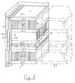
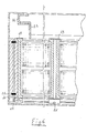
- thermoelectric installation of the "heat pump” type has been shown in which the thermoelements, generally designated by the reference numeral 1, are supplied with direct electric current to maintain a temperature difference between the heat exchange walls 2 and 3, on either side of each thermoelement 1.
- These heat exchange walls 2 and 3 belong to hot exchangers traversed by a hot fluid and to cold exchangers traversed by a fluid cold, the directions of circulation of these hot and cold fluids being identified in FIGS. 1 and 2 by the arrows F.
- thermoelectric installations As regards the supply of direct electric current to the thermoelements 1, this can be done by means of connection 4 supplied by wires 5, and by means of heat exchangers which are therefore traversed by the electric current which passes through the thermoelements 1.
- thermoelectric installations it has already been proposed to make them comprise stacks 6 of hot and cold exchangers alternating with the thermoelements 1, the exchanger or exchangers on either side of which are the thermoelements which are not electrically insulated and which can form a monobloc assembly these stacks 6 are arranged side by side and the electrical connection of the thermoelements between them made through the exchangers along a grinding path - line (mounting column).
- the exchanger or exchangers on either side of which the thermoelements are located can be electrically isolated; the stacks are then nested and the electrical connection of the thermoelements to each other is made by the base of the exchangers and following a route in Greek (bridge mounting).
- the stacks of exchangers arranged side by side or nested constitute a drawer 7 of parallelepipedal shape in which the thermoelements are in parallel planes and the exchangers facing each other others.
- the constituent elements of this drawer are held together by fixing means such, for example, as a central tie 8, and housed in a frame 9 in which are formed passages 9a allowing the circulation of hot fluid and cold fluid .
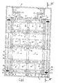
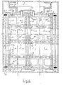
- thermoelements are provided at each plane of the thermoelements, this seal being constituted by a plate comprising as many openings 11 as there are thermoelements 1 in the above plan, this seal being pinched between the walls 2 and 3 opposite the hot and cold exchangers and comprising, in addition, a peripheral rim 12 provided, on its upper and lower faces, with a continuous groove 13, this peripheral rim in relief, coming to surround the exchangers disposed at the periphery of the drawer 7 .
- Each seal 10 can advantageously comprise, as shown in FIGS. 2 and 6, raised central ribs 14 which come to be interposed between the exchangers of the drawer 7 for, on the one hand, ensuring the seal between the exchangers and, on the other hand, playing the role of spacers ensuring the relative positioning of the exchangers with each other with a suspension and vibration damping effect.
- the two seals 10, located at the two ends of the drawer 7, are arranged differently to cooperate respectively with two end pieces 15, 16 biased towards each other by the central tie rod 8.
- Connection partitions 17, as shown in FIGS. 1, 2, 4 and 5, connect the seals 10, by their peripheral edge 12 where these connection partitions 17 are embedded in the continuous groove 13, on two of their opposite sides, parallel to the direction of flow of fluids.
- these connecting partitions 17 form, with the seals 10 and the heat exchange walls 2 and 3, sealed conduits for circulation of the hot or cold fluids in the drawer 7.
- Connecting devices between the drawer 7 and the frame 9 are provided to ensure the continuity of the passages 9a of the frame 9 with the spaces of the corresponding exchangers of the drawer 7.
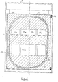
- a first support plate 18 is applied against a lateral face of the drawer 7 and fixed to the latter by a strip of adhesive material 19 surrounding it and adhering to the edges of the seals 10 and on the connecting partitions 17.
- the support plate 18 has openings 18a, corresponding to the passages 9a of the frame, and a groove 18b, of generally elliptical shape, surrounding the openings 18a and opening out through a window 18c.
- a second support plate 20 Facing this first support plate 18, a second support plate 20, with its openings 20a and its windows 20c, identical, is fixed to the frame 9.
- a collar 21, metallic or composite (metal and elastic material), is introduced, through the windows 18c and 20c of the plates 18 and 20, into the two grooves 18b and 20b to ensure the connection of the plates support 8 and 20 between them.
- the hot fluid cannot mix with the cold fluid.
- a seal 22, fixed to the frame 9, surrounds all of the passages 9a.
- FIGS. 1, 4 and 6 Such an arrangement is shown in FIGS. 1, 4 and 6.
- the seal between drawers is produced by a strip of adhesive material 19 surrounding the two adjacent ends of the neighboring drawers and coming to adhere to the edges of the seals 10 and on the connecting partitions 17 of each of the drawers. Only the two faces of the extreme drawers, close to the frame, are provided with support plates 18 intended to be secured to the support plates 20 of the frame 9.
- thermoelectric installation in which the seal between the hot fluid and the cold fluid is ensured by reliable and simple means since, in the frame, there can be no contact between the hot and cold fluids, one of the fluids being perfectly channeled in the drawers by the seals 10 and the connecting partitions 17; between the drawers by the strip of adhesive material 19; between the drawers and the frame, by the support plates 18 and 20 and the collar 21.
- the arrangement of the drawer in its frame allows the drawer to expand freely since the connections are provided by a strip of adhesive material 19 and a collar 21.
- This space can be used to receive the water contained in the air and condensed on contact with the heat exchange surfaces.
- this water can be easily evacuated by gravity into the "well” formed between drawers and / or between drawer and frame.
- the present invention therefore finds a particularly advantageous application in the air conditioning (heating and cooling) of railway cars which can then comprise, under their chassis, a whole series of frames each housing a drawer.
- air conditioning heating and cooling
- the problems of tightness, free expansion and ease of assembly and disassembly are particularly important and that the advantages provided by the invention will only be appreciated.
- the suspension and vibration damping effect caused by the seals and the drawer suspension system will allow the installation to be better withstand the conditions of use in railway cars.
Landscapes
- Engineering & Computer Science (AREA)
- Physics & Mathematics (AREA)
- Mechanical Engineering (AREA)
- Thermal Sciences (AREA)
- General Engineering & Computer Science (AREA)
- Gloves (AREA)
- Details Of Garments (AREA)
- Telephone Function (AREA)
- Electromagnetic Pumps, Or The Like (AREA)
- Cooling Or The Like Of Electrical Apparatus (AREA)
- Devices That Are Associated With Refrigeration Equipment (AREA)
- Heat-Exchange Devices With Radiators And Conduit Assemblies (AREA)
Priority Applications (1)
| Application Number | Priority Date | Filing Date | Title |
|---|---|---|---|
| AT80400201T ATE3219T1 (de) | 1979-02-22 | 1980-02-08 | Thermoelektrische anlage. |
Applications Claiming Priority (2)
| Application Number | Priority Date | Filing Date | Title |
|---|---|---|---|
| FR7904597A FR2449857A1 (fr) | 1979-02-22 | 1979-02-22 | Perfectionnements apportes aux installations thermoelectriques |
| FR7904597 | 1979-02-22 |
Publications (3)
| Publication Number | Publication Date |
|---|---|
| EP0016670A2 true EP0016670A2 (de) | 1980-10-01 |
| EP0016670A3 EP0016670A3 (en) | 1980-12-10 |
| EP0016670B1 EP0016670B1 (de) | 1983-05-04 |
Family
ID=9222337
Family Applications (1)
| Application Number | Title | Priority Date | Filing Date |
|---|---|---|---|
| EP80400201A Expired EP0016670B1 (de) | 1979-02-22 | 1980-02-08 | Thermoelektrische Anlage |
Country Status (4)
| Country | Link |
|---|---|
| EP (1) | EP0016670B1 (de) |
| AT (1) | ATE3219T1 (de) |
| DE (1) | DE3062921D1 (de) |
| FR (1) | FR2449857A1 (de) |
Cited By (1)
| Publication number | Priority date | Publication date | Assignee | Title |
|---|---|---|---|---|
| WO2007107403A1 (de) * | 2006-03-23 | 2007-09-27 | BSH Bosch und Siemens Hausgeräte GmbH | Wärmetauscheranordnung, insbesondere für ein hausgerät |
Family Cites Families (7)
| Publication number | Priority date | Publication date | Assignee | Title |
|---|---|---|---|---|
| US3196620A (en) * | 1964-02-10 | 1965-07-27 | Thore M Elfving | Thermoelectric cooling system |
| US3213630A (en) * | 1964-12-18 | 1965-10-26 | Westinghouse Electric Corp | Thermoelectric apparatus |
| US3474632A (en) * | 1968-10-21 | 1969-10-28 | Borg Warner | Thermoelectric conditioning apparatus |
| US3626704A (en) * | 1970-01-09 | 1971-12-14 | Westinghouse Electric Corp | Thermoelectric unit |
| US3899359A (en) * | 1970-07-08 | 1975-08-12 | John Z O Stachurski | Thermoelectric generator |
| FR2315771A1 (fr) * | 1975-06-27 | 1977-01-21 | Air Ind | Perfectionnements apportes aux installations thermo-electriques |
| FR2353138A2 (fr) * | 1975-06-27 | 1977-12-23 | Air Ind | Perfectionnements apportes aux installations thermoelectriques |
-
1979
- 1979-02-22 FR FR7904597A patent/FR2449857A1/fr active Granted
-
1980
- 1980-02-08 EP EP80400201A patent/EP0016670B1/de not_active Expired
- 1980-02-08 DE DE8080400201T patent/DE3062921D1/de not_active Expired
- 1980-02-08 AT AT80400201T patent/ATE3219T1/de not_active IP Right Cessation
Cited By (1)
| Publication number | Priority date | Publication date | Assignee | Title |
|---|---|---|---|---|
| WO2007107403A1 (de) * | 2006-03-23 | 2007-09-27 | BSH Bosch und Siemens Hausgeräte GmbH | Wärmetauscheranordnung, insbesondere für ein hausgerät |
Also Published As
| Publication number | Publication date |
|---|---|
| FR2449857B1 (de) | 1981-08-14 |
| ATE3219T1 (de) | 1983-05-15 |
| DE3062921D1 (en) | 1983-06-09 |
| EP0016670A3 (en) | 1980-12-10 |
| FR2449857A1 (fr) | 1980-09-19 |
| EP0016670B1 (de) | 1983-05-04 |
Similar Documents
| Publication | Publication Date | Title |
|---|---|---|
| EP2770809B1 (de) | Elektronische Karte | |
| EP1467607B1 (de) | Leistungsschaltermodul und Wechselrichter mit einem solchen Modul | |
| EP2653021B1 (de) | Kühlung einer elektronischen vorrichtung | |
| FR2809281A1 (fr) | Dispositif electronique de puissance | |
| CA1252508A (fr) | Installation de dissipation pour elements semi- conducteurs de puissance | |
| FR3049160A1 (fr) | Dispositif electronique et methode d'assemblage d'un tel dispositif | |
| FR2803166A1 (fr) | Module electronique a haut pouvoir de refroidissement | |
| EP3621093B1 (de) | Kapazitiver block mit einem kühlkörper | |
| EP1005083B1 (de) | Elektronisches Leistungselement mit Kühlvorrichtung | |
| EP0020758A1 (de) | Apparat zum erzeugen und speichern von energie | |
| EP0016670B1 (de) | Thermoelektrische Anlage | |
| FR2560476A1 (fr) | Element d'electronique aerospatiale | |
| FR2732819A1 (fr) | Thermoelement a dissipation concentrique | |
| JPH10321920A (ja) | 熱電変換装置 | |
| EP4345575B1 (de) | Verfahren zur herstellung eines kühlkörpers | |
| EP1259104B1 (de) | Leistungswandlersystem eines Schienenfahrzeuges | |
| JP2024025536A (ja) | 熱電発電モジュール及び熱電発電ユニット | |
| EP0734066B1 (de) | Elektronischer Leistungsmodul | |
| FR2786658A1 (fr) | Structure composite pour composant electronique de puissance procede de fabrication de cette structure et composant electronique de puissance pourvu d'une telle structure | |
| EP4082306A1 (de) | Wärmeableitungsvorrichtung, elektrisches system mit einer solchen vorrichtung und zugehöriges herstellungsverfahren | |
| JP4271012B2 (ja) | 電気車制御装置 | |
| EP4543183A1 (de) | Modul zur thermoelektrischen erzeugung und einheit zur thermoelektrischen erzeugung | |
| FR2463372A1 (fr) | Dispositif thermoelectrique a transfert de chaleur entre un premier fluide liquide et un deuxieme fluide | |
| FR2607911A1 (fr) | Dissipateur de chaleur a circulation de fluide et profile metallique permettant sa realisation | |
| FR2704310A1 (fr) | Echangeur à plaques et barrettes à circuits croisés. |
Legal Events
| Date | Code | Title | Description |
|---|---|---|---|
| PUAI | Public reference made under article 153(3) epc to a published international application that has entered the european phase |
Free format text: ORIGINAL CODE: 0009012 |
|
| AK | Designated contracting states |
Designated state(s): AT CH DE GB IT SE |
|
| PUAL | Search report despatched |
Free format text: ORIGINAL CODE: 0009013 |
|
| AK | Designated contracting states |
Designated state(s): AT CH DE GB IT SE |
|
| 17P | Request for examination filed |
Effective date: 19801128 |
|
| ITF | It: translation for a ep patent filed | ||
| GRAA | (expected) grant |
Free format text: ORIGINAL CODE: 0009210 |
|
| AK | Designated contracting states |
Designated state(s): AT CH DE GB IT SE |
|
| REF | Corresponds to: |
Ref document number: 3219 Country of ref document: AT Date of ref document: 19830515 Kind code of ref document: T |
|
| REF | Corresponds to: |
Ref document number: 3062921 Country of ref document: DE Date of ref document: 19830609 |
|
| PLBE | No opposition filed within time limit |
Free format text: ORIGINAL CODE: 0009261 |
|
| STAA | Information on the status of an ep patent application or granted ep patent |
Free format text: STATUS: NO OPPOSITION FILED WITHIN TIME LIMIT |
|
| 26N | No opposition filed | ||
| PGFP | Annual fee paid to national office [announced via postgrant information from national office to epo] |
Ref country code: AT Payment date: 19910124 Year of fee payment: 12 |
|
| PGFP | Annual fee paid to national office [announced via postgrant information from national office to epo] |
Ref country code: GB Payment date: 19910125 Year of fee payment: 12 |
|
| PGFP | Annual fee paid to national office [announced via postgrant information from national office to epo] |
Ref country code: DE Payment date: 19910220 Year of fee payment: 12 |
|
| ITTA | It: last paid annual fee | ||
| PGFP | Annual fee paid to national office [announced via postgrant information from national office to epo] |
Ref country code: SE Payment date: 19910228 Year of fee payment: 12 Ref country code: CH Payment date: 19910228 Year of fee payment: 12 |
|
| PG25 | Lapsed in a contracting state [announced via postgrant information from national office to epo] |
Ref country code: GB Effective date: 19920208 Ref country code: AT Effective date: 19920208 |
|
| PG25 | Lapsed in a contracting state [announced via postgrant information from national office to epo] |
Ref country code: SE Effective date: 19920209 |
|
| PG25 | Lapsed in a contracting state [announced via postgrant information from national office to epo] |
Ref country code: CH Effective date: 19920229 |
|
| GBPC | Gb: european patent ceased through non-payment of renewal fee | ||
| REG | Reference to a national code |
Ref country code: CH Ref legal event code: PL |
|
| PG25 | Lapsed in a contracting state [announced via postgrant information from national office to epo] |
Ref country code: DE Effective date: 19921103 |
|
| EUG | Se: european patent has lapsed |
Ref document number: 80400201.2 Effective date: 19920904 |