EP0016648B1 - A catalyst for cracking and/or oxidation of heavy hydrocarbons - Google Patents
A catalyst for cracking and/or oxidation of heavy hydrocarbons Download PDFInfo
- Publication number
- EP0016648B1 EP0016648B1 EP80300889A EP80300889A EP0016648B1 EP 0016648 B1 EP0016648 B1 EP 0016648B1 EP 80300889 A EP80300889 A EP 80300889A EP 80300889 A EP80300889 A EP 80300889A EP 0016648 B1 EP0016648 B1 EP 0016648B1
- Authority
- EP
- European Patent Office
- Prior art keywords
- catalyst
- iron
- tower
- cracking
- coke
- Prior art date
- Legal status (The legal status is an assumption and is not a legal conclusion. Google has not performed a legal analysis and makes no representation as to the accuracy of the status listed.)
- Expired
Links
Images


Classifications
-
- C—CHEMISTRY; METALLURGY
- C10—PETROLEUM, GAS OR COKE INDUSTRIES; TECHNICAL GASES CONTAINING CARBON MONOXIDE; FUELS; LUBRICANTS; PEAT
- C10G—CRACKING HYDROCARBON OILS; PRODUCTION OF LIQUID HYDROCARBON MIXTURES, e.g. BY DESTRUCTIVE HYDROGENATION, OLIGOMERISATION, POLYMERISATION; RECOVERY OF HYDROCARBON OILS FROM OIL-SHALE, OIL-SAND, OR GASES; REFINING MIXTURES MAINLY CONSISTING OF HYDROCARBONS; REFORMING OF NAPHTHA; MINERAL WAXES
- C10G11/00—Catalytic cracking, in the absence of hydrogen, of hydrocarbon oils
- C10G11/14—Catalytic cracking, in the absence of hydrogen, of hydrocarbon oils with preheated moving solid catalysts
- C10G11/18—Catalytic cracking, in the absence of hydrogen, of hydrocarbon oils with preheated moving solid catalysts according to the "fluidised-bed" technique
-
- B—PERFORMING OPERATIONS; TRANSPORTING
- B01—PHYSICAL OR CHEMICAL PROCESSES OR APPARATUS IN GENERAL
- B01J—CHEMICAL OR PHYSICAL PROCESSES, e.g. CATALYSIS OR COLLOID CHEMISTRY; THEIR RELEVANT APPARATUS
- B01J23/00—Catalysts comprising metals or metal oxides or hydroxides, not provided for in group B01J21/00
- B01J23/70—Catalysts comprising metals or metal oxides or hydroxides, not provided for in group B01J21/00 of the iron group metals or copper
- B01J23/74—Iron group metals
- B01J23/755—Nickel
-
- C—CHEMISTRY; METALLURGY
- C01—INORGANIC CHEMISTRY
- C01B—NON-METALLIC ELEMENTS; COMPOUNDS THEREOF; METALLOIDS OR COMPOUNDS THEREOF NOT COVERED BY SUBCLASS C01C
- C01B3/00—Hydrogen; Gaseous mixtures containing hydrogen; Separation of hydrogen from mixtures containing it; Purification of hydrogen; Reversible storage of hydrogen
- C01B3/02—Production of hydrogen; Production of gaseous mixtures containing hydrogen
- C01B3/06—Production of hydrogen; Production of gaseous mixtures containing hydrogen by reaction of inorganic compounds containing electro-positively bound hydrogen with inorganic reducing agents
- C01B3/061—Production of hydrogen; Production of gaseous mixtures containing hydrogen by reaction of inorganic compounds containing electro-positively bound hydrogen with inorganic reducing agents by reaction of water with metal oxides
- C01B3/063—Cyclic methods
-
- C—CHEMISTRY; METALLURGY
- C01—INORGANIC CHEMISTRY
- C01B—NON-METALLIC ELEMENTS; COMPOUNDS THEREOF; METALLOIDS OR COMPOUNDS THEREOF NOT COVERED BY SUBCLASS C01C
- C01B3/00—Hydrogen; Gaseous mixtures containing hydrogen; Separation of hydrogen from mixtures containing it; Purification of hydrogen; Reversible storage of hydrogen
- C01B3/02—Production of hydrogen; Production of gaseous mixtures containing hydrogen
- C01B3/06—Production of hydrogen; Production of gaseous mixtures containing hydrogen by reaction of inorganic compounds containing electro-positively bound hydrogen with inorganic reducing agents
- C01B3/08—Production of hydrogen; Production of gaseous mixtures containing hydrogen by reaction of inorganic compounds containing electro-positively bound hydrogen with inorganic reducing agents by reaction of inorganic compounds with metals
- C01B3/10—Production of hydrogen; Production of gaseous mixtures containing hydrogen by reaction of inorganic compounds containing electro-positively bound hydrogen with inorganic reducing agents by reaction of inorganic compounds with metals by reaction of water vapour with metals
-
- C—CHEMISTRY; METALLURGY
- C10—PETROLEUM, GAS OR COKE INDUSTRIES; TECHNICAL GASES CONTAINING CARBON MONOXIDE; FUELS; LUBRICANTS; PEAT
- C10G—CRACKING HYDROCARBON OILS; PRODUCTION OF LIQUID HYDROCARBON MIXTURES, e.g. BY DESTRUCTIVE HYDROGENATION, OLIGOMERISATION, POLYMERISATION; RECOVERY OF HYDROCARBON OILS FROM OIL-SHALE, OIL-SAND, OR GASES; REFINING MIXTURES MAINLY CONSISTING OF HYDROCARBONS; REFORMING OF NAPHTHA; MINERAL WAXES
- C10G11/00—Catalytic cracking, in the absence of hydrogen, of hydrocarbon oils
- C10G11/02—Catalytic cracking, in the absence of hydrogen, of hydrocarbon oils characterised by the catalyst used
-
- Y—GENERAL TAGGING OF NEW TECHNOLOGICAL DEVELOPMENTS; GENERAL TAGGING OF CROSS-SECTIONAL TECHNOLOGIES SPANNING OVER SEVERAL SECTIONS OF THE IPC; TECHNICAL SUBJECTS COVERED BY FORMER USPC CROSS-REFERENCE ART COLLECTIONS [XRACs] AND DIGESTS
- Y02—TECHNOLOGIES OR APPLICATIONS FOR MITIGATION OR ADAPTATION AGAINST CLIMATE CHANGE
- Y02E—REDUCTION OF GREENHOUSE GAS [GHG] EMISSIONS, RELATED TO ENERGY GENERATION, TRANSMISSION OR DISTRIBUTION
- Y02E60/00—Enabling technologies; Technologies with a potential or indirect contribution to GHG emissions mitigation
- Y02E60/30—Hydrogen technology
- Y02E60/36—Hydrogen production from non-carbon containing sources, e.g. by water electrolysis
Definitions
- This invention relates to a catalyst for cracking heavy hydrocarbons to produce a light oil, i.e., light gas and cracked oil, and for producing hydrogen by the reaction between the catalyst and steam utilizing an oxidation-reduction reaction.
- the inventors of the present invention have previously proposed a process which comprises catalytically cracking a heavy oil (e.g., atmospheric residual oil, vacuum residual oil) in the presence of a nickel ore, by which heavy metals contained in the heavy oil are removed and the heavy oil is cracked (see Japanese Patent Application (OPI) No. 10202/74).
- a heavy oil e.g., atmospheric residual oil, vacuum residual oil
- OPI Japanese Patent Application
- the inventors have found that, if the above-described heavy hydrocarbon is subjected to catalytic cracking in the presence of laterite or a laterite-containing catalyst, coke is formed on the laterite catalyst in a greater amount as the heavy hydrocarbon is cracked to a light oil, although the yield of cracked distillate oil is slightly decreased when compared to the use of the above-described nickel ore.
- the laterite catalyst on which the coke is deposited is heated in a gas stream, the iron oxides in the laterite catalyst are very rapidly reduced and hydrogen is easily formed by the steam-iron reaction.
- the inventors have also proposed a process for producing a cracked distillate and hydrogen from a heavy oil which comprises cracking the heavy oil in the presence of laterite or a laterite-containing catalyst while simultaneously depositing coke on the laterite or laterite-containing catalyst, reducing the laterite or laterite-containing catalyst on which the coke is deposited while simultaneously burning the coke in a reducing atmosphere, and forming a hydrogen- rich gas by contacting the reduced laterite or laterite-containing catalyst with steam (see Japanase Patent Application (OPI) No. 47708/79, Japanese Patent Application No. 9413/79 and U.S. Patent Application No. 22,385, filed March 21, 1979).
- OPI Japanase Patent Application
- an object of the present invention is to provide a catalyst suitable for conducting in a stable manner and over a long period of time, a process for cracking and/or oxidizing a heavy hydrocarbon and also for producing hydrogen by reaction between the catalyst and steam.
- the invention resides in a catalyst for use in a process under fluidizing conditions, for oxidizing and/or cracking a heavy hydrocarbon in the presence of the catalyst and producing hydrogen by reacting a reduced oxidation-state iron as metallic iron and iron oxides having a small oxidation number in the catalyst with steam, and said catalyst consisting of from 30 to 60 wt% Fe as Fe 2 0 3 , 0.1 to 10 wt% Ni as NiO, and up to 10 wt% Si0 2 , the balance being an inorganic refractory material, and having a specific surface area of from 0.1 to 30 m 2 /g and an apparent specific gravity of from 2.5 to 4.0.
- the catalyst according to the present invention will now be explained in terms of its chemical state, particularly that of the Fe, at different times during the process.
- the iron is converted into various oxidation states, i.e., metallic iron, iron oxides (FeO, Fe 3 0 4 and Fe z 0 3 ), and iron sulfide.
- reduced oxidation state iron means metallic iron and iron oxides having a small oxidation number, such as the type of iron oxides referred to as "iron suboxides".
- the iron suboxides refer to FeO and Fe 3 0 4 , both of which have a small oxidation number among the iron oxides, and particularly to a suboxide containing FeO as a main ingredient.
- the term “reduction rate” (abbreviated as "R") is used. This term is based on the amount of oxygen chemically combined with the iron, and when all of the iron in the catalyst is converted to Fe 2 0 3 (that is, where the Fe has the highest possible oxidation number among the iron oxides), this is defined as 0%.
- the reduction rate R is given by the following equation: Therefore, when all of the iron in the catalyst is present in the state of metallic Fe, the reduction rate is 100%, and when all of the iron is present in the state of FeO, then the reduction rate becomes 66.7%. Further, if the iron is all present in an Fe 3 0 4 state, the reduction rate is 1 1 . 1%.
- the oxidation state of iron changes at each reaction stage.
- iron is not present in a single oxidation state, and thus the reduced oxidation-state iron may have a reduction rate of, for example, 60% or 30%, i.e., the reduction rate varies depending upon the ratio of Fe, FeO and Fe 3 0 4 in the catalyst.
- a heavy hydrocarbon (H) is cracked in a cracking tower (1) to produce light oils (L) such as light gas and cracked oil, and also coke.
- Coke deposited on the catalyst is transferred into a regeneration tower (2) and partially combusted by feeding oxygen-containing gas (A), such as air, in an amount not enough for complete combustion of the coke.
- oxygen-containing gas (A) such as air
- the iron component in the catalyst is reduced by the gas containing carbon-monoxide and hydrogen and/or by coke in the tower.
- Exhaust gas (G) is withdrawn from the top of tower (2).
- the reduced oxidation-state iron catalyst is then charged into a gasification tower (3) and reacts with steam (S) to produce hydrogen (G').
- the presence of CaO in the catalyst accelerates the sulfur-capturing effect, due to formation of calcium sulfide.
- the catalyst-captured sulfur i.e., iron sulfide and calcium sulfide, reacts with steam (S) and the sulfur is released from the catalyst and converted to hydrogen sulfide, whereas the catalyst is regenerated in an oxidized state.
- introduction of carbon dioxide gas together with steam into the gasification tower (3) further accelerates the catalyst-regenerating effect.
- the regenerated catalyst is returned into the cracking tower (1) through the line (8).
- Figure 2 shows a two tower system, one being the regeneration tower (4) and the other being the gasification tower (5). Partial combustion of heavy hydrocarbon, reduction of the catalyst with carbon monoxide gas and/or coke and also heating of the catalyst occur in the regeneration tower (4). Reaction between steam and iron to produce hydrogen, and oxidation of the catalyst with steam occur in the gasification tower (5). This process will be explained in more detail below.
- a heavy hydrocarbon (H) is combusted in the fluidized state with an oxygen-containing gas (A) (e.g., air) being supplied in an amount to provide less than the amount of oxygen theoretically required for complete combustion and, at the same time, the iron component in the catalyst is reduced by gas containing CO and H 2 , and/or by coke in the regeneration tower (4).
- A oxygen-containing gas
- the reduced oxidation-state iron in the catalyst reacts with steam (S) to produce hydrogen (G') and, at the same time, the reduced oxidation-state iron in the catalyst is oxidized by steam in the gasification tower (5).
- the heat produced in the regeneration tower (4) can be used for steam generation for example.
- the catalyst is passed from the top of the regeneration tower (4) to the bottom of the gasification tower (5) via conduit (9), then moves up through the tower (5) and returns to the regeneration tower (4) via conduit (9').
- Figure 3 shows a process which employs three towers, a first regeneration tower (6), a second regeneration tower (6') and a gasification tower (7).
- a heavy hydrocarbon is combusted in the fluidized state with an oxygen-containing gas (A) in an amount to provide less than the amount of oxygen theoretically required for complete combustion.
- iron oxides in the catalyst are reduced by the gas containing CO and H 2 and/or by coke and the used gas is withdrawn from the top of the tower (6).
- Coke deposited on the catalyst is removed by subjecting it to combustion under a reducing atmosphere produced by feeding an oxygen-containing gas (A') into the second regeneration tower (6') while withdrawing a gas (G") containing CO, CO 2 , H 2 , etc., from the top of the tower (6') and hydrogen (G') is produced by the reaction between the reduced oxidation-state iron and steam (S) in gasification tower (7).
- the sulfur compound when processing a high-sulfur heavy hydrocarbon according to the process (2) or (3), the sulfur compound reacts with reduced oxidation-state iron in the catalyst to form iron sulfide in the regeneration towers (4), (6) and (6').
- the catalyst including the captured sulfur compound in turn reacts with steam (S) in the gasification towers (7) and (5) to release the sulfur compound in the catalyst as hydrogen sulfide and, at the same time, the catalyst is thus regenerated in an oxidized state.
- heavy hydrocarbons that can be processed according to the above-described processes (1), (2) and (3), include residual oils, e.g., atmospheric residual oil, vacuum residual oil and a solvent-deasphalting residue obtained from crude oil, tar sand, oil shale and liquefied coal oil.
- Solid state heavy hydrocarbons, such as coal, asphaltene and resins can also be processed.
- the steam-iron reaction proceeds faster as the reduction rate R of the iron component increases.
- the reduction rate R in the above-described processes (1), (2) and (3) varies depending upon the reaction temperature and the catalyst residence time but, usually, an iron component with a reduction rate R of about 25 to 45% provides an extremely fast oxidation reaction, and no differences are observed at 700 to 800°C, though the oxidation reaction becomes slightly slower at 600°C or less.
- most of the coke deposited on the catalyst to be used for the steam-iron reaction is removed before being introduced into the gasification tower.
- the iron component must be properly dispersed in the catalyst using an inorganic refractory material, such as AI 2 0 3 and/or MgO, which serves to increase the surface area and enhance the catalyst activity.
- Another problem is that, when cracking or partially combusting a heavy hydrocarbon, coking often takes place within, or at the outlet of, the cracking and/or regeneration towers. Utilization of heat energy to heat low temperature parts or of kinetic energy to scrape off coke from the catalyst particles is effective for decoking. Such a method can be effective for scraping the coke deposited at the outlet of a reaction tower by the catalyst particles blown up to the outlet. These methods necessitate the use of a catalyst with definite strength and density properties.
- the catalyst of the present invention consisting essentially of from 30 to 60 wt% Fe as Fe 2 0 3 , 0.1 to 10 wt% Ni as NiO and 10 wt% or less Si0 2 the balance being an inorganic refractory material and having a specific surface area of from 0.1 to 30 m 2 /g and an apparent specific gravity of from 2.5 to 4.0 satisfies the above-described requirements.
- the inorganic refractory material is preferably AI Z 0 3 , MgO or a mixture of two or more of AI 2 0 3 , Mgo and CaO.
- the reason for limiting the iron content in the above-described composition of the catalyst to from 30 to 60 wt% is that: (I) if the content is less than 30 wt%, the amount of H 2 to be produced in the gasification tower by the steam-iron reaction decreases, and the proportion of a water gas reaction between coke and steam increases, thus the H 2 concentration in the gas being decreased; in addition, the sulfur-capturing ratio in the regeneration tower decreases; and (ii) if the content exceeds 60 wt%, bogging is likely to occur.
- Ni promotes the aforesaid reaction (1) of cracking a heavy hydrocarbon, and has the effect of depositing coke, necessary in the iron oxides-reducing step, on the catalyst, i.e., it has the effect of raising the yield of coke.
- Ni has the effect of accelerating the foregoing iron sulfide- decomposing reaction (6) between iron sulfide and steam.
- Ni must be incorporated in a content of at least 0.1 wt% but, if the content exceeds 10 wt%, there results nickel ferrite which increases sintering of iron and therefore inhibits the foregoing reaction (5).
- Ni must be incorporated within the range of from 0.1 to 10 wt%.
- Si0 2 also contributes to the cracking of a heavy hydrocarbon to some extent, but it primarily functions as an iron-dispersing agent to prevent bogging of the catalyst.
- Si0 2 has also been found to influence the aforesaid reaction (5) in long term use of the catalyst. Possibly, the Si0 2 forms a complex salt with reduced oxidation-state iron, thus inhibiting the reaction between steam and iron. Therefore, the Si0 2 content should be not more than 10 wt%.
- CaO is preferably incorporated in an amount of from 0.01 to 20 wt%. If the content exceeds 20 wt%, there results a decrease in the H 2 concentration in the gasification tower (as a result of acceleration of water gas reaction) and a reduction in the strength of the catalyst occurs. On the other hand, since CaO accelerates not only the reduction reaction of the iron oxides but also the capture of sulfur, it is preferably incorporated in a content of 0.01 wt% or more.
- an inorganic refractory material e.g. AI 2 0 3 and/or MgO
- an inorganic refractory material e.g. AI 2 0 3 and/or MgO
- the specific surface area was measured according to ASTM D3663-1978.
- the catalyst In order to improve the attrition resistance of the catalyst during use in the processes as described and to raise the aforsaid decoking efficiency at the outlet of a reaction tower, the catalyst must have an apparent specific gravity of at least 2.5.
- the strength of the catalyst corresponds directly to the apparent specific gravity. However, if the apparent specific gravity is too high, attrition of the reactors and pipework, etc. would occur. Since the above-described surface area also decreases as the apparent specific gravity increases, we have found that the apparent specific gravity must be 2.5 to 4.0 with consideration for the balance of these factors.
- This apparent specific gravity can be simply and relatively accurately determined according to a method of using a mercury porosimeter, placing a 0.5 g sample in a vessel, filling it with mercury, and after bringing the vessel to lower pressure restoring it to atmosphere pressure, and measuring the amount of mercury, from which the apparent specific gravity can be calculated.
- materials containing iron in an extremely high amounts such as ores containing iron in the form of the hydroxide, oxide or carbonate (e.g., laterite, magnetite, siderite, hematite, limonite), or chemical compositions of iron oxides, hydroxides or carbonates are used, and are appropriately mixed with other materials such as an NiO powder, alumina, magnesia, silica, calcium hydroxide, nickel ores such as garnierite, dolomite, limestone, to obtain the desired composition.
- ores containing iron in the form of the hydroxide, oxide or carbonate e.g., laterite, magnetite, siderite, hematite, limonite
- chemical compositions of iron oxides, hydroxides or carbonates are used, and are appropriately mixed with other materials such as an NiO powder, alumina, magnesia, silica, calcium hydroxide, nickel ores such as garnierite, dolomite, limestone, to obtain the desired composition.
- the catalyst may also be prepared by mixing compounds of hydroxides, oxides, carbonates, sulfates, nitrates, chlorides, sulfides or the like of Fe, Ni, Al, Mg, Si, Ca, or appropriate ores containing them to obtain the desired composition. In either case, it is important to satisfy the above-described composition ratios.
- the above-described composition is pulverized, kneaded, granulated, and calcined to prepare the catalyst having the aforesaid physical properties.
- the conditions of these procedures for preparing the catalyst depend upon the particular above-described raw materials and the composition of the desired catalyst.
- catalysts with the required specific surface area and apparent specific gravity can be obtained by pulverizing, kneading with well controlling water content, granulating, and calcining the ores.
- iron ores which have suffered from almost no weathering require, in some cases, some pretreatment such as treatment with an acid or alkali. Differences in the raw material generally influence the specific surface area and the apparent specific gravity of the catalyst thus prepared.
- the smaller particle size of the pulverized raw material the easier the subsequent kneading procedure.
- the pulverized raw material preferably has a particle size of l0,um or less.
- the type of kneader used and the amount of water added influences the apparent specific gravity. In general, as the water content increases, the apparent specific gravity decreases.
- Examples of granulating methods include spray-granulating, crush-granulating, extrusion- granulating, roll-granulating, compression-granulating. These methods influence the apparent specific gravity of the resulting catalyst.
- catalysts prepared by the spray-granulating method have a smaller-apparent specific gravity than catalysts prepared by the crush-granulating method, and the compression-granulating methods provides catalyst with an extremely large apparent specific gravity.
- the catalyst to be used in this process preferably has a mean particle size of from 60 to 600 j um, and hence granulation is preferably effected to obtain this particle size.
- the calcining temperature and time considerably affect the specific surface area and the apparent specific gravity of the resulting catalyst. As the calcining temperature and the calcining time are increased, the specific surface area decreases and the apparent specific gravity increases. When the calcining temperature exceeds 1,200°C, the results obtained are undesirable. On the other hand, when the calcining temperature is lower than 900°C, the apparent specific gravity is undesirably low.
- Catalysts with the aforesaid given specific surface area and apparent specific gravity can be prepared by appropriately controlling the above-described conditions in such a manner that the resulting catalyst has a specific surface area of from 0.1 to 30 m 2 /g and an apparent specific gravity of from 2.5 to 4.0.
- the oil is introduced via conduit (14) into a fluidized bed held at 450 to 600°C under a pressure of 0 to 15 kg/cm 2 G (gauge pressure) at the lower part of a cracking tower (11).
- the granular catalyst is fluidized by a fluidizing gas introduced through a conduit (15).
- Steam is usually used as the fluidizing gas, although a hydrocarbon gas such as a cracked light gas may also be used.
- the oil is catalytically cracked by the catalyst to form a light gas, cracked oil and coke. The light gas and the cracked oil are removed and recovered in the gaseous state, together with the fluidizing gas, via a conduit (16).
- the coke deposits on the catalyst.
- the amount of coke deposited on the catalyst increases.
- the amount of deposited coke is preferably controlled within the range of from 2 wt% to 15 wt%, and preferably from 2 to 8 wt%, based on the total weight of catalyst. If the amount of coke deposited is too small, iron oxides in the laterite catalyst are not reduced sufficiently in the subsequent process steps. On the other hand, if the amount of coke deposited on the catalyst is too high, the activity of the catalyst decreases, so that the yield of the cracked oil is lowered, and the coke does not fully solidify on the catalyst, thus leading to the formation of agglomerated particles. Thus, such amounts are not preferable.
- the sulfur compounds are concentrated and deposited on the catalyst together with the coke.
- the thus coke-laden catalyst is transferred to a regeneration tower (12) via conduit (17).
- the regeneration tower (12) is kept at a temperature of from 750 to 950°C and a pressure of from 0 to 15 kg/cm 2 G (gauge pressure), and the coke deposited on the catalyst is partially combusted with an oxygen-containing gas fed via conduit (18) to provide the quantity of heat necessary for the entire system and to reduce the iron oxides in the catalyst. It is believed that the reduced catalyst is obtained by reducion of the iron oxides in the catalyst according to the following reduction equations (1) to (6).
- reaction temperature is increased or as the amount of coke deposited on the catalyst is increased.
- a reaction temperature higher than 950°C is not preferred for economic reasons because the reactor may be damaged and bogging may occur in service. Accordingly, it is preferred to use a temperature of about 750 to 950°C.
- the reduction is preferably carried out such that the amount of coke deposited on the catalyst is about 2 to 15 wt% based on the total weight of the catalyst.
- the exhaust gas containing CO 2 and CO produced by the reactions between iron oxides and coke and between coke and oxygen is discharged via conduit (19).
- the catalyst particles heated to from 750 to 950°C are transferred to the cracking tower (11) and a gasification tower (13) via conduits (20) and (21), respectively.
- the reducted oxidation-state iron-containing catalyst is charged to the gasification tower (13) via transfer conduit (21 where it undergoes oxidation with steam fed via conduit (22) to produce hydrogen.
- the temperature and the pressure within the gasification tower are kept at 600 to 850°C and 0 to 15 kg/cm 2 G (gauge pressure), respectively.
- the reaction between the reduced oxidation-state iron and steam proceeds according to the following equations (9) to (11).
- the above-described reactions are advantageously carried out at lower temperatures for thermodynamic reasons.
- a temperature between the cracking temperature and the catalyst regeneration temperature e.g. a temperature between about 600 and 950°C.
- the sulfur which has been captured by the catalyst in the form of iron sulfide and calcium sulfide reacts with steam.
- the catalyst is regenerated to form the oxides and the sulfur compounds are released as hydrogen sulfide.
- introduction of carbon dioxide gas together with the steam accelerates this regeneration effect.
- part of the coke on the catalyst reacts with steam to cause the water gas reaction according to the following equations (12) and (13) thereby to decrease the hydrogen concentration:
- equations (12) and (13) thereby to decrease the hydrogen concentration:
- the use of the catalyst of the present invention is advantageous in that a heavy hydrocarbon can be catalytically cracked using a catalyst capable of being prepared in a simple manner to produce in an industrially advantageous manner, a cracked oil such as cracked light gas and cracked oil, and also to produce hydrogen.
- the process using the catalyst of the invention has the merit of advantageously producing hydrogen in an industrial process by the partial combustion of a heavy hydrocarbon.
- Fe 2 O 3 , NiO, Al 2 O 3 , SiO 2 , MgO, and Ca(OH) 2 were mixed as raw materials and pulverized to obtain a particle size of 10 ⁇ or less. Then, water was added thereto and the mixture was kneaded for 15 minutes before crushing and granulation. The granulated product was calcined at 1,200°C for 3 hours to obtain catalysts with different compositions having a mean particle size of 0.2 mm as shown in Table 1. The specific surface area and the apparent specific gravity of these catalysts were 1.6 to 2.0 m 2 /g and 3.5 to 3.8, respectively. These catalysts were partially sulfided with H 2 S at 850°C to prepare catalysts containing about 0.8 wt% sulfur.
- the catalyst was fed to the cracking tower at a rate of 16 kg/hr.
- catalysts containing from 30 to 60 wt% Fe as Fe 2 O 3 and from 0.1 to 10 wt% Ni as NiO are found to be useful in the described process, and it is seen that as the Ni content increases, the coke-deposition ratio upon cracking a heavy oil also increases, which is advantageous in the subsequent reduction step.
- a catalyst was prepared in the same manner as described in Example 1 using laterite ore, with calcining at 1,250°C for 10 hours.
- the resulting catalyst contained 55.4 wt% Fe as Fe 2 O 3 , 1.4 wt% Ni as NiO, and 8.4 wt% (Al 2 O 3 +MgO+SiO 2 ), and had a specific surface area of 0.07 m /g.
- the results obtained by the same procedure as described above using this catalyst are also shown in Table 5 as Comparative Example 2.
- Laterite ores containing 55.2 wt% Fe, 1.35 wt% Ni, 1.1 wt% MgO, 3.44 wt% Si0 2 , and 4.01 wt% Al 2 O 3 were pulverized to a particle size of 10 ⁇ m or less, water was added thereto, and the mixture was kneaded, crushed, and granulated to prepare the samples of Examples 2 to 5 and Comparative Example 3.
- Calcining temperature and time were changed among the Examples 2 to 5 and Comparative Example 3 as shown in Table 6.
- the particle size of all catalysts was conditioned to be in the range of from 149 ⁇ to 250 ⁇ with use of the sieves.
- a particle size of the catalysts was in the range of from 190 to 200 p.
- Fluid attrition resistance was measured in a manner described below using an apparatus shown in Figure 6.
- the apparatus shown in Figure 6 is composed of a catalyst tube (61) having an inside diameter of 11 2 inches (3.81 cm) and a height of 271 2 inches (69.85 cm) at the bottom portion of which a perforated plate (62) having four pores (0.015 inch (0.038 cm) in diameter) is provided.
- a perforated plate (62) having four pores (0.015 inch (0.038 cm) in diameter
- Connected to the upper portion of the tube (61) is an upper tube (64), having an inside diameter of 5 inches (12.7 cm), a height of 18 inches (45.72 cm), and a converging portion (63) with a height of 4 inches (10.16 cm).
- the upper portion of the upper tube (64) is connected to a flask (66) via a glass tube (65) and a pinch lamp (67).
- Flask (66) is further connected to an extraction thimble (68) via a hose clamp (69).
- the bottom end of the catalyst tube (61) is connected to an air line (70), which is equipped with an air filter (71), a a pressure regulator (72), a rotameter (73), a flow controller (74), and pressure gauges (75) and (76).
- the reactors were made of stainless steel.
- the cracking tower had a diameter of 5 inches (12.7 cm) and a height of 1.6 m
- the regeneration tower had a diameter of 6 inches (15.24) and a height of 1.8 m
- the gasification tower had a diameter of 4 inches (10.16 cm) and a height of 1.9 m, with a cyclone being provided at the outlet of each tower.
- the heavy oil used as the same as in Example 1.
- a laterite ore was pulverized, kneaded, granulated, dried, and calcined at 1,160°C for 3 hours to prepare catalyst particles having a particle size in the range of from 70 to 400 p.
- the composition of the calcined catalyst was: Fe 2 O 3 : 49.7 wt% (as Fe); NiO: 1.44 wt% (as Ni; Al 2 O 3 : 2.85 wt%; MgO: 5.54 wt%; Si0 2 : 1.81 wt%; CaO: 0.04 wt%.
- Example 7 Also, the same operation was conducted using a catalyst prepared in the same manner as in Example 7 and containing 37.7 wt% Fe 2 0 3 as Fe, 2.0 wt% NiO as Ni, 1.3 wt% AI 2 0 3 , 19.6 wt% MgO, and 12.6 wt% Si0 2 . Results thus obtained are also shown in Table 7 as Comparative Example 5.
Landscapes
- Chemical & Material Sciences (AREA)
- Organic Chemistry (AREA)
- Chemical Kinetics & Catalysis (AREA)
- Engineering & Computer Science (AREA)
- Oil, Petroleum & Natural Gas (AREA)
- General Chemical & Material Sciences (AREA)
- Health & Medical Sciences (AREA)
- General Health & Medical Sciences (AREA)
- Combustion & Propulsion (AREA)
- Inorganic Chemistry (AREA)
- Materials Engineering (AREA)
- Production Of Liquid Hydrocarbon Mixture For Refining Petroleum (AREA)
- Catalysts (AREA)
Description
- This invention relates to a catalyst for cracking heavy hydrocarbons to produce a light oil, i.e., light gas and cracked oil, and for producing hydrogen by the reaction between the catalyst and steam utilizing an oxidation-reduction reaction.
- As a catalyst for cracking heavy hydrocarbons such as atmospheric residual oil, vacuum residual oil, solvent-deasphalting residue, it has been heretofore proposed to use nickel-containing ore calcined at 900 to 1,200°C [see Japanese Patent Application (OPI) No. 72388/77 (the term "OPI" as used herein refers to a "published unexamined Japanese Patent Application") and U.S. Patent 4,114,324]. However, the catalyst prepared only by calcining at 900°C to 1200°C does not have a satisfactory combination of composition and physical properties to be satisfactory for use over an extended period of time as a catalyst for oxidizing and/or cracking heavy hydrocarbons and producing hydrogen.
- Also, the inventors of the present invention have previously proposed a process which comprises catalytically cracking a heavy oil (e.g., atmospheric residual oil, vacuum residual oil) in the presence of a nickel ore, by which heavy metals contained in the heavy oil are removed and the heavy oil is cracked (see Japanese Patent Application (OPI) No. 10202/74).
- As a result of further investigations, the inventors have found that, if the above-described heavy hydrocarbon is subjected to catalytic cracking in the presence of laterite or a laterite-containing catalyst, coke is formed on the laterite catalyst in a greater amount as the heavy hydrocarbon is cracked to a light oil, although the yield of cracked distillate oil is slightly decreased when compared to the use of the above-described nickel ore. When the laterite catalyst on which the coke is deposited is heated in a gas stream, the iron oxides in the laterite catalyst are very rapidly reduced and hydrogen is easily formed by the steam-iron reaction. Thus, the inventors have also proposed a process for producing a cracked distillate and hydrogen from a heavy oil which comprises cracking the heavy oil in the presence of laterite or a laterite-containing catalyst while simultaneously depositing coke on the laterite or laterite-containing catalyst, reducing the laterite or laterite-containing catalyst on which the coke is deposited while simultaneously burning the coke in a reducing atmosphere, and forming a hydrogen- rich gas by contacting the reduced laterite or laterite-containing catalyst with steam (see Japanase Patent Application (OPI) No. 47708/79, Japanese Patent Application No. 9413/79 and U.S. Patent Application No. 22,385, filed March 21, 1979).
- As a result of further investigations into catalysts for use in the above-described process, the inventors have discovered that:
- (i) A laterite catalyst which contains a high content of Si02 suffers serious deterioration of catalytic activity when used for a long period of time.
- (ii) Among the catalysts prepared from laterite, only those with specific physical properties can be stably used for a long period of time.
- (iii) Catalysts other than laterite can exhibit similar effects as long as they have specific compositions and physical properties.
- Therefore, an object of the present invention is to provide a catalyst suitable for conducting in a stable manner and over a long period of time, a process for cracking and/or oxidizing a heavy hydrocarbon and also for producing hydrogen by reaction between the catalyst and steam.
- Accordingly, the invention resides in a catalyst for use in a process under fluidizing conditions, for oxidizing and/or cracking a heavy hydrocarbon in the presence of the catalyst and producing hydrogen by reacting a reduced oxidation-state iron as metallic iron and iron oxides having a small oxidation number in the catalyst with steam, and said catalyst consisting of from 30 to 60 wt% Fe as
Fe 203, 0.1 to 10 wt% Ni as NiO, and up to 10 wt% Si02, the balance being an inorganic refractory material, and having a specific surface area of from 0.1 to 30 m2/g and an apparent specific gravity of from 2.5 to 4.0. - The catalyst according to the present invention will now be explained in terms of its chemical state, particularly that of the Fe, at different times during the process.
- When the Fe-containing catalyst is used in a process as described herein, at different times during the process, the iron is converted into various oxidation states, i.e., metallic iron, iron oxides (FeO,
Fe 304 and Fez03), and iron sulfide. - The term "reduced oxidation state iron" as used herein means metallic iron and iron oxides having a small oxidation number, such as the type of iron oxides referred to as "iron suboxides". The iron suboxides refer to FeO and
Fe 304, both of which have a small oxidation number among the iron oxides, and particularly to a suboxide containing FeO as a main ingredient. - In order to express the degree of reduction of catalyst, the term "reduction rate" (abbreviated as "R") is used. This term is based on the amount of oxygen chemically combined with the iron, and when all of the iron in the catalyst is converted to Fe203 (that is, where the Fe has the highest possible oxidation number among the iron oxides), this is defined as 0%. In other words, the reduction rate R is given by the following equation:

Fe 304 state, the reduction rate is 1 1 . 1%. - When the catalyst according to the present invention is used in the cracking of a heavy hydrocarbon and in the generation of hydrogen, the oxidation state of iron changes at each reaction stage. In addition, iron is not present in a single oxidation state, and thus the reduced oxidation-state iron may have a reduction rate of, for example, 60% or 30%, i.e., the reduction rate varies depending upon the ratio of Fe, FeO and
Fe 304 in the catalyst. - Several embodiments of the above-described process will now be described with reference to the accompanying drawings, in which:-
- Figures 1, 2 and 3 are flow sheets showing processes to which the catalyst of the present invention can be applied,
- Figures 4 and 5 are flow sheets showing processes employed in Examples of the present invention,
- Figure 6 shows apparatus for measuring the fluid attrition resistance of the catalyst, and
- Figure 7 is a graph showing the relationship between the apparent specific gravity and the fluid attrition resistance.
- Referring to Figure 1, a heavy hydrocarbon (H) is cracked in a cracking tower (1) to produce light oils (L) such as light gas and cracked oil, and also coke. Coke deposited on the catalyst is transferred into a regeneration tower (2) and partially combusted by feeding oxygen-containing gas (A), such as air, in an amount not enough for complete combustion of the coke. At the same time, the iron component in the catalyst is reduced by the gas containing carbon-monoxide and hydrogen and/or by coke in the tower. Exhaust gas (G) is withdrawn from the top of tower (2). The reduced oxidation-state iron catalyst is then charged into a gasification tower (3) and reacts with steam (S) to produce hydrogen (G'). When cracking high-sulfur heavy hydrocarbons, sulfur compounds in the heavy hydrocarbons are concentrated and deposited on the catalyst together with coke in the cracking tower (1). Then, the sulfur compounds on the catalyst react with the reduced oxidation-state iron in the regeneration tower (2) to form iron sulfide. Thus, the sulfur content in the light oil is drastically reduced.
- In this situation, the presence of CaO in the catalyst accelerates the sulfur-capturing effect, due to formation of calcium sulfide. Furthermore, in the gasification tower (3) the catalyst-captured sulfur, i.e., iron sulfide and calcium sulfide, reacts with steam (S) and the sulfur is released from the catalyst and converted to hydrogen sulfide, whereas the catalyst is regenerated in an oxidized state. In this situation, introduction of carbon dioxide gas together with steam into the gasification tower (3) further accelerates the catalyst-regenerating effect. The regenerated catalyst is returned into the cracking tower (1) through the line (8).
- Figure 2 shows a two tower system, one being the regeneration tower (4) and the other being the gasification tower (5). Partial combustion of heavy hydrocarbon, reduction of the catalyst with carbon monoxide gas and/or coke and also heating of the catalyst occur in the regeneration tower (4). Reaction between steam and iron to produce hydrogen, and oxidation of the catalyst with steam occur in the gasification tower (5). This process will be explained in more detail below.
- A heavy hydrocarbon (H) is combusted in the fluidized state with an oxygen-containing gas (A) (e.g., air) being supplied in an amount to provide less than the amount of oxygen theoretically required for complete combustion and, at the same time, the iron component in the catalyst is reduced by gas containing CO and H2, and/or by coke in the regeneration tower (4). Subsequently, the reduced oxidation-state iron in the catalyst reacts with steam (S) to produce hydrogen (G') and, at the same time, the reduced oxidation-state iron in the catalyst is oxidized by steam in the gasification tower (5). The heat produced in the regeneration tower (4) can be used for steam generation for example. The catalyst is passed from the top of the regeneration tower (4) to the bottom of the gasification tower (5) via conduit (9), then moves up through the tower (5) and returns to the regeneration tower (4) via conduit (9').
- Figure 3 shows a process which employs three towers, a first regeneration tower (6), a second regeneration tower (6') and a gasification tower (7).
- In tower (6), a heavy hydrocarbon (H) is combusted incompletely, a gas containing carbon monoxide, hydrogen, etc, is produced, and coke is deposited on the catalyst. Coke on the catalyst is combusted completely in the second regeneration tower (6'), and hydrogen gas is produced by the reaction between steam and iron in the gasification tower (7). This process will be explained in more detail below.
- A heavy hydrocarbon is combusted in the fluidized state with an oxygen-containing gas (A) in an amount to provide less than the amount of oxygen theoretically required for complete combustion. At the same time, iron oxides in the catalyst are reduced by the gas containing CO and H2 and/or by coke and the used gas is withdrawn from the top of the tower (6). Coke deposited on the catalyst is removed by subjecting it to combustion under a reducing atmosphere produced by feeding an oxygen-containing gas (A') into the second regeneration tower (6') while withdrawing a gas (G") containing CO, CO2, H2, etc., from the top of the tower (6') and hydrogen (G') is produced by the reaction between the reduced oxidation-state iron and steam (S) in gasification tower (7).
- Additionally, as in process (1), when processing a high-sulfur heavy hydrocarbon according to the process (2) or (3), the sulfur compound reacts with reduced oxidation-state iron in the catalyst to form iron sulfide in the regeneration towers (4), (6) and (6'). The catalyst including the captured sulfur compound in turn reacts with steam (S) in the gasification towers (7) and (5) to release the sulfur compound in the catalyst as hydrogen sulfide and, at the same time, the catalyst is thus regenerated in an oxidized state.
- Examples of heavy hydrocarbons that can be processed according to the above-described processes (1), (2) and (3), include residual oils, e.g., atmospheric residual oil, vacuum residual oil and a solvent-deasphalting residue obtained from crude oil, tar sand, oil shale and liquefied coal oil. Solid state heavy hydrocarbons, such as coal, asphaltene and resins can also be processed.
- In the process in which the catalyst of the present invention is intended to be used:
- (i) all of the reactions are conducted in a fluidized state;
- (ii) the reaction may be carried out at atmospheric pressure or elevated pressure, which is selected according to the condition of the generated hydrogen used, and in general, it is performed at a pressure of 0 to 15 kg/cm2G; and
- (iii) a reaction temperature between 450 and 950°C is used, with the temperature of the reaction between the reduced oxidation-state iron and steam, the so-called steam-iron reaction, being suitably conducted at about 600 to 850°C.
- The steam-iron reaction proceeds faster as the reduction rate R of the iron component increases. The reduction rate R in the above-described processes (1), (2) and (3) varies depending upon the reaction temperature and the catalyst residence time but, usually, an iron component with a reduction rate R of about 25 to 45% provides an extremely fast oxidation reaction, and no differences are observed at 700 to 800°C, though the oxidation reaction becomes slightly slower at 600°C or less. In the above-described processes, most of the coke deposited on the catalyst to be used for the steam-iron reaction is removed before being introduced into the gasification tower. However, a small amount of coke remains deposited on the catalyst and, when the reaction temperature of the steam-iron reaction exceeds 850°C, a water gas reaction takes place to such an extent that the amounts of CO and CO2 in the H2 produced increases to as to complicate subsequent hydrogen purification.
- As is described above, the processes with which the catalyst of the invention is concerned involve the following six reactions:
- (1) the reaction of cracking a heavy hydrocarbon;
- (2) the partial combustion of the heavy hydrocarbon and/or coke;
- (3) the reaction of reducing iron oxides;
- (4) the reaction between reduced oxidation-state iron and sulfur;
- (5) the reaction between the reduced oxidation-state iron and steam; and
- (6) the reaction between iron sulfide and steam.
- These reactions require catalyst which are stable under the reaction conditions for a long period of time. In addition, the agglomeration of catalyst particles to each other, the so-called bogging phenomenon, and the strength of the catalyst, i.e., the attrition resistance, must also be taken into consideration. For example, FeO, one form of reduced oxidation-state iron, causes sintering of the catalyst at 760 to 850°C. This sintering reduces the surface area of the catalyst, which hinders the steam-iron reaction. Furthermore, the catalyst particles are caused to adhere or agglomerate to each other to form large masses; when this occurs fluidization of the catalyst is inhibited and it is difficult to transfer the catalyst particles from one tower to another. Thus, continuous operation of the process becomes impossible. Therefore, it is very important to select the catalyst in which these phenomena do not occur. The iron component must be properly dispersed in the catalyst using an inorganic refractory material, such as
AI 203 and/or MgO, which serves to increase the surface area and enhance the catalyst activity. - Another problem is that, when cracking or partially combusting a heavy hydrocarbon, coking often takes place within, or at the outlet of, the cracking and/or regeneration towers. Utilization of heat energy to heat low temperature parts or of kinetic energy to scrape off coke from the catalyst particles is effective for decoking. Such a method can be effective for scraping the coke deposited at the outlet of a reaction tower by the catalyst particles blown up to the outlet. These methods necessitate the use of a catalyst with definite strength and density properties.
- The catalyst of the present invention consisting essentially of from 30 to 60 wt% Fe as
Fe 203, 0.1 to 10 wt% Ni as NiO and 10 wt% or less Si02 the balance being an inorganic refractory material and having a specific surface area of from 0.1 to 30 m2/g and an apparent specific gravity of from 2.5 to 4.0 satisfies the above-described requirements. The inorganic refractory material is preferablyAI Z03, MgO or a mixture of two or more ofAI 203, Mgo and CaO. The reason for limiting the iron content in the above-described composition of the catalyst to from 30 to 60 wt% is that: (I) if the content is less than 30 wt%, the amount of H2 to be produced in the gasification tower by the steam-iron reaction decreases, and the proportion of a water gas reaction between coke and steam increases, thus the H2 concentration in the gas being decreased; in addition, the sulfur-capturing ratio in the regeneration tower decreases; and (ii) if the content exceeds 60 wt%, bogging is likely to occur. - Ni promotes the aforesaid reaction (1) of cracking a heavy hydrocarbon, and has the effect of depositing coke, necessary in the iron oxides-reducing step, on the catalyst, i.e., it has the effect of raising the yield of coke. In addition, Ni has the effect of accelerating the foregoing iron sulfide- decomposing reaction (6) between iron sulfide and steam. For these purposes, Ni must be incorporated in a content of at least 0.1 wt% but, if the content exceeds 10 wt%, there results nickel ferrite which increases sintering of iron and therefore inhibits the foregoing reaction (5). Thus, Ni must be incorporated within the range of from 0.1 to 10 wt%.
- Furthermore, Si02 also contributes to the cracking of a heavy hydrocarbon to some extent, but it primarily functions as an iron-dispersing agent to prevent bogging of the catalyst. However, Si02 has also been found to influence the aforesaid reaction (5) in long term use of the catalyst. Possibly, the Si02 forms a complex salt with reduced oxidation-state iron, thus inhibiting the reaction between steam and iron. Therefore, the Si02 content should be not more than 10 wt%.
- Also, CaO is preferably incorporated in an amount of from 0.01 to 20 wt%. If the content exceeds 20 wt%, there results a decrease in the H2 concentration in the gasification tower (as a result of acceleration of water gas reaction) and a reduction in the strength of the catalyst occurs. On the other hand, since CaO accelerates not only the reduction reaction of the iron oxides but also the capture of sulfur, it is preferably incorporated in a content of 0.01 wt% or more.
- Furthermore, in order to improve the ratio of decomposing sulfides, to improve the catalyst strength, to improve the bogging-preventing effect, and to accelerate the cracking of a hydrocarbon, it is necessary to incorporate an inorganic refractory material,
e.g. AI 203 and/or MgO, generally in an amount of from 5 to 60 wt%, based on the total weight of the composition. If the amount is less than 5 wt%, bogging-prevention seriously deteriorates, while if more than 60 wt%, a decrease in the amount of hydrogen produced in the gasification tower and a reduction in the sulfur-capturing efficiency in the regeneration tower occurs. - We have found that even catalysts having the above-described composition do not show a sufficient activity in the cracking of a heavy hydrocarbon, the reducing of the iron oxides, or in the steam-iron reaction unless they have a specific surface area of more than 0.1 m2/g. We have found that, in the above-described processes, well balanced progress of the six reactions requires a specific surface area of at least 0.1 m2/g. However, if the surface area exceeds 30 m2/g, we have found that attrition loss of the catalyst increases due to too much powdering. Also, it should be noted that the specific surface area decreases in the course of long term use of the catalyst. For example, a catalyst initially having a specific surface area of 10 m2/g suffered a reduction in the specific surface area to about 0.5 m2/g after being used for about 80 hours in the aforesaid process (1) during which time, however, the process worked well.
- The specific surface area was measured according to ASTM D3663-1978.
- In order to improve the attrition resistance of the catalyst during use in the processes as described and to raise the aforsaid decoking efficiency at the outlet of a reaction tower, the catalyst must have an apparent specific gravity of at least 2.5. The strength of the catalyst corresponds directly to the apparent specific gravity. However, if the apparent specific gravity is too high, attrition of the reactors and pipework, etc. would occur. Since the above-described surface area also decreases as the apparent specific gravity increases, we have found that the apparent specific gravity must be 2.5 to 4.0 with consideration for the balance of these factors. This apparent specific gravity can be simply and relatively accurately determined according to a method of using a mercury porosimeter, placing a 0.5 g sample in a vessel, filling it with mercury, and after bringing the vessel to lower pressure restoring it to atmosphere pressure, and measuring the amount of mercury, from which the apparent specific gravity can be calculated.
- In preparing the above-described catalyst, materials containing iron in an extremely high amounts, such as ores containing iron in the form of the hydroxide, oxide or carbonate (e.g., laterite, magnetite, siderite, hematite, limonite), or chemical compositions of iron oxides, hydroxides or carbonates are used, and are appropriately mixed with other materials such as an NiO powder, alumina, magnesia, silica, calcium hydroxide, nickel ores such as garnierite, dolomite, limestone, to obtain the desired composition. The catalyst may also be prepared by mixing compounds of hydroxides, oxides, carbonates, sulfates, nitrates, chlorides, sulfides or the like of Fe, Ni, Al, Mg, Si, Ca, or appropriate ores containing them to obtain the desired composition. In either case, it is important to satisfy the above-described composition ratios.
- The above-described composition is pulverized, kneaded, granulated, and calcined to prepare the catalyst having the aforesaid physical properties. The conditions of these procedures for preparing the catalyst depend upon the particular above-described raw materials and the composition of the desired catalyst. When using, for example, natural ores which have suffered from extreme weathering, such as laterite, catalysts with the required specific surface area and apparent specific gravity can be obtained by pulverizing, kneading with well controlling water content, granulating, and calcining the ores. However, iron ores which have suffered from almost no weathering require, in some cases, some pretreatment such as treatment with an acid or alkali. Differences in the raw material generally influence the specific surface area and the apparent specific gravity of the catalyst thus prepared.
- Regarding pulverization, the smaller particle size of the pulverized raw material the easier the subsequent kneading procedure. In general, it is impossible to pulverize the particles to a size small enough to influence the specific surface area of the prepared catalyst, but the particle size of raw material after pulverization does influence the apparent specific gravity, or the attrition resistance of the resulting catalyst. That is, catalysts with more uniform attrition resistance can be prepared by using a smaller particle size raw material, which serves to decrease the powdering tendency of the catalyst during the long-term use in the process. In general, the pulverized raw material preferably has a particle size of l0,um or less.
- Regarding the kneading conditions, the type of kneader used and the amount of water added influences the apparent specific gravity. In general, as the water content increases, the apparent specific gravity decreases.
- Examples of granulating methods include spray-granulating, crush-granulating, extrusion- granulating, roll-granulating, compression-granulating. These methods influence the apparent specific gravity of the resulting catalyst. For example, catalysts prepared by the spray-granulating method have a smaller-apparent specific gravity than catalysts prepared by the crush-granulating method, and the compression-granulating methods provides catalyst with an extremely large apparent specific gravity. Additionally, the catalyst to be used in this process preferably has a mean particle size of from 60 to 600 jum, and hence granulation is preferably effected to obtain this particle size.
- The calcining temperature and time considerably affect the specific surface area and the apparent specific gravity of the resulting catalyst. As the calcining temperature and the calcining time are increased, the specific surface area decreases and the apparent specific gravity increases. When the calcining temperature exceeds 1,200°C, the results obtained are undesirable. On the other hand, when the calcining temperature is lower than 900°C, the apparent specific gravity is undesirably low.
- Catalysts with the aforesaid given specific surface area and apparent specific gravity can be prepared by appropriately controlling the above-described conditions in such a manner that the resulting catalyst has a specific surface area of from 0.1 to 30 m2/g and an apparent specific gravity of from 2.5 to 4.0.
- A practical procedure according to the aforesaid process (1) for using the catalyst of the present invention will be described below, particularly for applying the process to a vacuum residual oil. Reference is made to the flow sheet shown in Figure 4.
- In Figure 4, the oil is introduced via conduit (14) into a fluidized bed held at 450 to 600°C under a pressure of 0 to 15 kg/cm2G (gauge pressure) at the lower part of a cracking tower (11). In the fluidized bed, the granular catalyst is fluidized by a fluidizing gas introduced through a conduit (15). Steam is usually used as the fluidizing gas, although a hydrocarbon gas such as a cracked light gas may also be used. In the cracking tower (11), the oil is catalytically cracked by the catalyst to form a light gas, cracked oil and coke. The light gas and the cracked oil are removed and recovered in the gaseous state, together with the fluidizing gas, via a conduit (16). On the other hand, the coke deposits on the catalyst. With the continuation of the above-described catalytic cracking, the amount of coke deposited on the catalyst increases. In the present invention, the amount of deposited coke is preferably controlled within the range of from 2 wt% to 15 wt%, and preferably from 2 to 8 wt%, based on the total weight of catalyst. If the amount of coke deposited is too small, iron oxides in the laterite catalyst are not reduced sufficiently in the subsequent process steps. On the other hand, if the amount of coke deposited on the catalyst is too high, the activity of the catalyst decreases, so that the yield of the cracked oil is lowered, and the coke does not fully solidify on the catalyst, thus leading to the formation of agglomerated particles. Thus, such amounts are not preferable. When processing a high-sulfur oil, the sulfur compounds are concentrated and deposited on the catalyst together with the coke.
- The thus coke-laden catalyst is transferred to a regeneration tower (12) via conduit (17). The regeneration tower (12) is kept at a temperature of from 750 to 950°C and a pressure of from 0 to 15 kg/cm2G (gauge pressure), and the coke deposited on the catalyst is partially combusted with an oxygen-containing gas fed via conduit (18) to provide the quantity of heat necessary for the entire system and to reduce the iron oxides in the catalyst. It is believed that the reduced catalyst is obtained by reducion of the iron oxides in the catalyst according to the following reduction equations (1) to (6).


- The above reduction reactions are more advantageously carried out as the reaction temperature is increased or as the amount of coke deposited on the catalyst is increased. However, a reaction temperature higher than 950°C is not preferred for economic reasons because the reactor may be damaged and bogging may occur in service. Accordingly, it is preferred to use a temperature of about 750 to 950°C. As previously described, the reduction is preferably carried out such that the amount of coke deposited on the catalyst is about 2 to 15 wt% based on the total weight of the catalyst. Furthermore, in the above-described reduction, the entire system is heated by partial combustion of coke according to the following equations (7) and (8):


- The exhaust gas containing CO2 and CO produced by the reactions between iron oxides and coke and between coke and oxygen is discharged via conduit (19). The catalyst particles heated to from 750 to 950°C are transferred to the cracking tower (11) and a gasification tower (13) via conduits (20) and (21), respectively. The reducted oxidation-state iron-containing catalyst is charged to the gasification tower (13) via transfer conduit (21 where it undergoes oxidation with steam fed via conduit (22) to produce hydrogen. Additionally, the temperature and the pressure within the gasification tower are kept at 600 to 850°C and 0 to 15 kg/cm2G (gauge pressure), respectively. The reaction between the reduced oxidation-state iron and steam proceeds according to the following equations (9) to (11).



- The above-described reactions are advantageously carried out at lower temperatures for thermodynamic reasons. However, from the viewpoint of practical operation, it is preferred to use a temperature between the cracking temperature and the catalyst regeneration temperature, e.g. a temperature between about 600 and 950°C. Also, the sulfur which has been captured by the catalyst in the form of iron sulfide and calcium sulfide reacts with steam. Thus, the catalyst is regenerated to form the oxides and the sulfur compounds are released as hydrogen sulfide. In this situation, introduction of carbon dioxide gas together with the steam accelerates this regeneration effect.
- Additionally, in the above-described gasification tower (13), part of the coke on the catalyst reacts with steam to cause the water gas reaction according to the following equations (12) and (13) thereby to decrease the hydrogen concentration:


- Thus, since the oxidation of reduced oxidation-state iron shown in equations (9) to (11) chiefly occurs in the gasification tower (13), the hydrogen concentration in the gas discharged from conduit (23) of the gasification tower (13) is very high, generally 80 wt% by volume or more in the dry state. The thus-oxidized catalyst is circulated back to the cracking tower (11) via conduit (24).
- As will be understood from the above description, the use of the catalyst of the present invention is advantageous in that a heavy hydrocarbon can be catalytically cracked using a catalyst capable of being prepared in a simple manner to produce in an industrially advantageous manner, a cracked oil such as cracked light gas and cracked oil, and also to produce hydrogen.
- Furthermore, the process using the catalyst of the invention has the merit of advantageously producing hydrogen in an industrial process by the partial combustion of a heavy hydrocarbon.
- The present invention will now be described in more detail by reference to the following examples, for purposes of illustrating, but not limiting the scope of this invention.
- Fe2O3, NiO, Al2O3, SiO2, MgO, and Ca(OH)2 were mixed as raw materials and pulverized to obtain a particle size of 10 µ or less. Then, water was added thereto and the mixture was kneaded for 15 minutes before crushing and granulation. The granulated product was calcined at 1,200°C for 3 hours to obtain catalysts with different compositions having a mean particle size of 0.2 mm as shown in Table 1. The specific surface area and the apparent specific gravity of these catalysts were 1.6 to 2.0 m2/g and 3.5 to 3.8, respectively. These catalysts were partially sulfided with H2S at 850°C to prepare catalysts containing about 0.8 wt% sulfur.
- Each of the above-described catalysts was used for the process as illustrated in appended Figure 5, and the procedures of heavy oil cracking (51), regeneration (52) and gasification (53) were conducted in a single-pass manner. Dimensions of the equipment used and the properties of the oil were as follows.

- The composition of the catalyst used in each run is shown in Table 1.
- The catalyst was fed to the cracking tower at a rate of 16 kg/hr.

- The results of the operations in the cracking tower (51), regeneration tower (52), and gasification tower (53) are shown in the following Tables 2, 3 and 4, respectively.
-

-


- As is shown above, catalysts containing from 30 to 60 wt% Fe as Fe2O3 and from 0.1 to 10 wt% Ni as NiO are found to be useful in the described process, and it is seen that as the Ni content increases, the coke-deposition ratio upon cracking a heavy oil also increases, which is advantageous in the subsequent reduction step.
- The results obtained by the same procedures as described in Example 1 except for using a catalyst containing 13.5 wt% Fe as Fe2O3, 2.8 wt% Ni as NiO, 0.8 wt% CaO, and 82.9 wt% (Al2O3+MgO+SiO2) are tabulated in Table 5 as Comparative Example 1.
- Separately, a catalyst was prepared in the same manner as described in Example 1 using laterite ore, with calcining at 1,250°C for 10 hours. The resulting catalyst contained 55.4 wt% Fe as Fe2O3, 1.4 wt% Ni as NiO, and 8.4 wt% (Al2O3+MgO+SiO2), and had a specific surface area of 0.07 m /g. The results obtained by the same procedure as described above using this catalyst are also shown in Table 5 as Comparative Example 2.
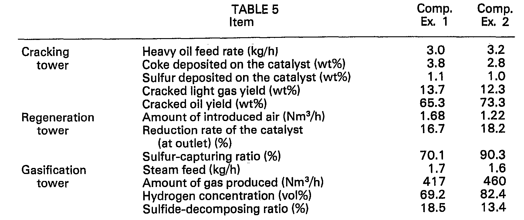
- As is seen from the above results, the gas in the gasification tower was produced in a small amount in the Comparative Examples, and, in Comparative Example 1, the hydrogen concentration was relatively low.
- Laterite ores containing 55.2 wt% Fe, 1.35 wt% Ni, 1.1 wt% MgO, 3.44 wt% Si02, and 4.01 wt% Al2O3 were pulverized to a particle size of 10 µm or less, water was added thereto, and the mixture was kneaded, crushed, and granulated to prepare the samples of Examples 2 to 5 and Comparative Example 3.
- Calcining temperature and time were changed among the Examples 2 to 5 and Comparative Example 3 as shown in Table 6. The particle size of all catalysts was conditioned to be in the range of from 149 µ to 250 µ with use of the sieves. A particle size of the catalysts was in the range of from 190 to 200 p.
- In addition to these samples, a laterite ore containing 43.6 wt% Fe, 2.1 wt% Ni, 9.1 wt% MgO, 11.2 wt% Si02 and 4.6
wt% AI 203 was similarly processed to prepare the sample of Example 6. The results obtained are also shown in Table 6. - The same laterite ores as used in Examples 2 to 5 were similarly pulverized, kneaded, and granulated using a spray granulator. The resulting granules were calcined at 1,200°C for 3 hours to prepare a catalyst having a particle size of 149 to 250 p.
- Fluid attrition resistance was measured in a manner described below using an apparatus shown in Figure 6.
- The apparatus shown in Figure 6 is composed of a catalyst tube (61) having an inside diameter of 11 2 inches (3.81 cm) and a height of 271 2 inches (69.85 cm) at the bottom portion of which a perforated plate (62) having four pores (0.015 inch (0.038 cm) in diameter) is provided. Connected to the upper portion of the tube (61) is an upper tube (64), having an inside diameter of 5 inches (12.7 cm), a height of 18 inches (45.72 cm), and a converging portion (63) with a height of 4 inches (10.16 cm). The upper portion of the upper tube (64) is connected to a flask (66) via a glass tube (65) and a pinch lamp (67). Flask (66) is further connected to an extraction thimble (68) via a hose clamp (69). The bottom end of the catalyst tube (61) is connected to an air line (70), which is equipped with an air filter (71), a a pressure regulator (72), a rotameter (73), a flow controller (74), and pressure gauges (75) and (76).
- 5 g of water was added to a 45 g dry catalyst, and the resulting mixture was charged in a catalyst tube. Then, air was introduced so that the superficial velocity in the catalyst tube became 94 cm/sec., and the dust trapped in the extraction thimble after 5, 10 and 45 hours was weighed. The powdering ratio for each time period was calculated, and the resulting ratios were plotted versus time to determine the fime for a powdering ratio of 1 %.
- The results of fluid attrition resistance tests on Examples 2 to 6 and Comparative Examples 3 and 4 are shown in Table 6.

- As is seen from the above results, there is no definite relationship between the apparent specific gravity and the specific surface area due to the influence of the composition. However, the apparent specific gravity and the powdering ratio of the catalyst or the fluid attrition resistance used as a measure for indicating the strength of the catalyst are in the relation as shown in Figure 7. As can be seen from Figure 7, the smaller the apparent specific gravity, the more the powdering.
- Using the three-towered equipment shown in Figure 4, a heavy oil was cracked and hydrogen was produced. The reactors were made of stainless steel. The cracking tower had a diameter of 5 inches (12.7 cm) and a height of 1.6 m, the regeneration tower had a diameter of 6 inches (15.24) and a height of 1.8 m, and the gasification tower had a diameter of 4 inches (10.16 cm) and a height of 1.9 m, with a cyclone being provided at the outlet of each tower. The heavy oil used as the same as in Example 1. A laterite ore was pulverized, kneaded, granulated, dried, and calcined at 1,160°C for 3 hours to prepare catalyst particles having a particle size in the range of from 70 to 400 p. The composition of the calcined catalyst was: Fe2O3: 49.7 wt% (as Fe); NiO: 1.44 wt% (as Ni; Al2O3: 2.85 wt%; MgO: 5.54 wt%; Si02: 1.81 wt%; CaO: 0.04 wt%.
- The results after 100 hour operation are shown in Table 7 as Example 7.
- Also, the same operation was conducted using a catalyst prepared in the same manner as in Example 7 and containing 37.7
wt% Fe 203 as Fe, 2.0 wt% NiO as Ni, 1.3wt% AI 203, 19.6 wt% MgO, and 12.6 wt% Si02. Results thus obtained are also shown in Table 7 as Comparative Example 5. - Additionally, the operating conditions employed are as follows:
- Pressure, 0-1 kg/cm2G (gauge pressure)
- Cracking tower : reaction temperature, 540°C; catalyst hold-up, 10 kg; amount of catalyst circulated from cracking tower to regeneration tower, 40 kg/h; heavy oil- feeding rate, 4.3 kg/h; steam-feeding rate, 29 kg/h
- Regeneration tower : reaction temperature, 830°C; catalyst hold-up, 11 kg; air-feeding rate, 2 m 3/h
- Gasification tower : reaction temperature, 750°C; catalyst hold-up, 12 kg; steam-feeding rate, 1.9 kg/h

- As is seen from the above results, when Si02 is included in a large amount, a decrease in the amount of hydrogen produced in the gasification tower occurred during long-term use of the catalyst.
Claims (3)
Applications Claiming Priority (2)
| Application Number | Priority Date | Filing Date | Title |
|---|---|---|---|
| JP32269/79 | 1979-03-22 | ||
| JP54032269A JPS5951336B2 (en) | 1979-03-22 | 1979-03-22 | Catalyst for treatment of heavy hydrocarbons |
Publications (2)
| Publication Number | Publication Date |
|---|---|
| EP0016648A1 EP0016648A1 (en) | 1980-10-01 |
| EP0016648B1 true EP0016648B1 (en) | 1983-09-07 |
Family
ID=12354273
Family Applications (1)
| Application Number | Title | Priority Date | Filing Date |
|---|---|---|---|
| EP80300889A Expired EP0016648B1 (en) | 1979-03-22 | 1980-03-21 | A catalyst for cracking and/or oxidation of heavy hydrocarbons |
Country Status (6)
| Country | Link |
|---|---|
| US (1) | US4308173A (en) |
| EP (1) | EP0016648B1 (en) |
| JP (1) | JPS5951336B2 (en) |
| AU (1) | AU521691B2 (en) |
| CA (1) | CA1142163A (en) |
| DE (1) | DE3064728D1 (en) |
Families Citing this family (15)
| Publication number | Priority date | Publication date | Assignee | Title |
|---|---|---|---|---|
| JPS5837353B2 (en) * | 1979-09-29 | 1983-08-16 | 重質油対策技術研究組合 | Decomposition of heavy oil to make it lighter and hydrogen production method |
| JPS5836034B2 (en) * | 1980-12-22 | 1983-08-06 | 重質油対策技術研究組合 | Method for producing reduced iron through pyrolysis of heavy oil |
| JPS57135890A (en) * | 1981-02-13 | 1982-08-21 | Res Assoc Residual Oil Process<Rarop> | Cracking and conversion into light oil of heavy oil and preparation of hydrogen |
| US4451578A (en) * | 1982-04-26 | 1984-05-29 | United Technologies Corporation | Iron oxide catalyst for steam reforming |
| US4414099A (en) * | 1982-09-13 | 1983-11-08 | Exxon Research And Engineering Co. | Fluid coking with the addition of alkaline earth metal ferrite-containing catalysts |
| US4664777A (en) * | 1984-07-30 | 1987-05-12 | Exxon Research And Engineering Company | Process for improving octane by the conversion of fused multi-ring aromatics and hydroaromatics to lower molecular weight compounds |
| GB8419851D0 (en) * | 1984-08-03 | 1984-09-05 | Ici Plc | Catalyst production |
| US4678557A (en) * | 1985-09-09 | 1987-07-07 | Intevep, S.A. | Process for the regeneration of spent catalyst used in the upgrading of heavy hydrocarbon feedstocks |
| US4751210A (en) * | 1987-05-21 | 1988-06-14 | Intevep, S.A. | Regeneration of an iron based natural catalyst used in the hydroconversion of heavy crudes and residues |
| US5814164A (en) * | 1994-11-09 | 1998-09-29 | American Scientific Materials Technologies L.P. | Thin-walled, monolithic iron oxide structures made from steels, and methods for manufacturing such structures |
| US6461562B1 (en) | 1999-02-17 | 2002-10-08 | American Scientific Materials Technologies, Lp | Methods of making sintered metal oxide articles |
| NL1011627C2 (en) * | 1999-03-22 | 2000-09-27 | Plug Power Inc | Process for the selective oxidation of hydrocarbons. |
| CA2340822C (en) * | 2000-03-17 | 2010-08-03 | Snamprogetti S.P.A. | Process for the production of hydrogen |
| ITMI20030192A1 (en) * | 2003-02-05 | 2004-08-06 | Eni Spa | CATALYTIC SYSTEM AND PRODUCTION PROCESS |
| CA2991801C (en) * | 2015-07-17 | 2023-08-15 | Nicolas Abatzoglou | Process for producing catalysts from mining residue and catalysts produced therefrom |
Family Cites Families (4)
| Publication number | Priority date | Publication date | Assignee | Title |
|---|---|---|---|---|
| GB586914A (en) * | 1942-02-27 | 1947-04-08 | Standard Oil Dev Co | Improved process for the production of hydrogen |
| US3726791A (en) * | 1970-07-16 | 1973-04-10 | Exxon Research Engineering Co | Hydrogen production from an integrated coker gasifier system |
| US4115324A (en) * | 1977-06-10 | 1978-09-19 | Nippon Mining Co., Ltd | Catalyst for treating heavy oils |
| JPS55104920A (en) * | 1979-01-30 | 1980-08-11 | Nippon Mining Co Ltd | Manufacture of lightened oil and hydrogen from heavy oil |
-
1979
- 1979-03-22 JP JP54032269A patent/JPS5951336B2/en not_active Expired
-
1980
- 1980-03-21 DE DE8080300889T patent/DE3064728D1/en not_active Expired
- 1980-03-21 EP EP80300889A patent/EP0016648B1/en not_active Expired
- 1980-03-21 AU AU56734/80A patent/AU521691B2/en not_active Ceased
- 1980-03-21 CA CA000348209A patent/CA1142163A/en not_active Expired
- 1980-03-24 US US06/132,955 patent/US4308173A/en not_active Expired - Lifetime
Also Published As
| Publication number | Publication date |
|---|---|
| JPS5951336B2 (en) | 1984-12-13 |
| AU5673480A (en) | 1980-09-25 |
| US4308173A (en) | 1981-12-29 |
| JPS55124542A (en) | 1980-09-25 |
| EP0016648A1 (en) | 1980-10-01 |
| CA1142163A (en) | 1983-03-01 |
| AU521691B2 (en) | 1982-04-22 |
| DE3064728D1 (en) | 1983-10-13 |
Similar Documents
| Publication | Publication Date | Title |
|---|---|---|
| US4308173A (en) | Catalyst for cracking heavy hydrocarbons | |
| EP0110704B1 (en) | Improved preparative process for alkaline earth metal, aluminum-containing spinels | |
| US5972835A (en) | Fluidizable particulate materials and methods of making same | |
| GB2040991A (en) | Process for producing cracked distillate and hydrogen from heavy oil | |
| EP0110703B1 (en) | Improved preparative process for alkaline earth metal, aluminum-containing spinels | |
| US4673557A (en) | Process for removing hydrogen sulfide from gases | |
| JPS5827837B2 (en) | Processing method for sulfur-containing heavy oil | |
| EP0026645B1 (en) | Process for cracking heavy hydrocarbons into light oils and for producing hydrogen, and so produced light oil and hydrogen | |
| JPS6312115B2 (en) | ||
| JPH022917B2 (en) | ||
| US4597856A (en) | Process for fluidized catalytic cracking of heavy oils and production of hydrogen | |
| CA2122160C (en) | Synthesis gas from particulate catalysts, and admixtures of particulate catalysts and heat transfer solids | |
| US4399023A (en) | Process for simultaneously cracking heavy hydrocarbons into light oils and producing hydrogen | |
| US4421635A (en) | Process for simultaneously cracking heavy hydrocarbons into light oils and producing hydrogen | |
| CA1055920A (en) | Supported cobalt sulfate desulfurization catalyst | |
| JPS6172601A (en) | Thermal cracking of heavy hydrocarbons and production of light hydrocarbons and hydrogen | |
| CA1133843A (en) | Process for processing sulfur-containing heavy oil | |
| US4025460A (en) | Catalyst for gasification of heavy hydrocarbons in fluidized bed | |
| US20030162850A1 (en) | Hydrocarbon synthesis catalyst and process | |
| CA1118400A (en) | Catalyst useful for methanation and preparation thereof | |
| AU689931B2 (en) | Process for selective catalyst particle size control by ex situ grinding to maintain bed fluidization during high temperature operations | |
| EP0060618B1 (en) | Process for simultaneously cracking heavy hydrocarbons into light oils and producing hydrogen, and light oils and hydrogen when so produced | |
| US2560345A (en) | Pretreatment of catalyst for hydrocarbon synthesis | |
| JPS5951335B2 (en) | Catalyst for treatment of heavy oil containing high sulfur content | |
| JPS6348801B2 (en) |
Legal Events
| Date | Code | Title | Description |
|---|---|---|---|
| PUAI | Public reference made under article 153(3) epc to a published international application that has entered the european phase |
Free format text: ORIGINAL CODE: 0009012 |
|
| AK | Designated contracting states |
Designated state(s): BE DE FR GB IT NL |
|
| 17P | Request for examination filed |
Effective date: 19810217 |
|
| ITF | It: translation for a ep patent filed | ||
| GRAA | (expected) grant |
Free format text: ORIGINAL CODE: 0009210 |
|
| AK | Designated contracting states |
Designated state(s): BE DE FR GB IT NL |
|
| REF | Corresponds to: |
Ref document number: 3064728 Country of ref document: DE Date of ref document: 19831013 |
|
| ET | Fr: translation filed | ||
| PGFP | Annual fee paid to national office [announced via postgrant information from national office to epo] |
Ref country code: FR Payment date: 19840227 Year of fee payment: 5 |
|
| PGFP | Annual fee paid to national office [announced via postgrant information from national office to epo] |
Ref country code: BE Payment date: 19840331 Year of fee payment: 5 |
|
| PLBE | No opposition filed within time limit |
Free format text: ORIGINAL CODE: 0009261 |
|
| STAA | Information on the status of an ep patent application or granted ep patent |
Free format text: STATUS: NO OPPOSITION FILED WITHIN TIME LIMIT |
|
| 26N | No opposition filed | ||
| PG25 | Lapsed in a contracting state [announced via postgrant information from national office to epo] |
Ref country code: BE Effective date: 19860331 |
|
| BERE | Be: lapsed |
Owner name: NIPPON MINING CY LTD Effective date: 19860331 |
|
| PG25 | Lapsed in a contracting state [announced via postgrant information from national office to epo] |
Ref country code: FR Free format text: LAPSE BECAUSE OF NON-PAYMENT OF DUE FEES Effective date: 19861128 |
|
| REG | Reference to a national code |
Ref country code: FR Ref legal event code: ST |
|
| PGFP | Annual fee paid to national office [announced via postgrant information from national office to epo] |
Ref country code: GB Payment date: 19920312 Year of fee payment: 13 |
|
| PGFP | Annual fee paid to national office [announced via postgrant information from national office to epo] |
Ref country code: NL Payment date: 19920331 Year of fee payment: 13 |
|
| PGFP | Annual fee paid to national office [announced via postgrant information from national office to epo] |
Ref country code: DE Payment date: 19920430 Year of fee payment: 13 |
|
| PG25 | Lapsed in a contracting state [announced via postgrant information from national office to epo] |
Ref country code: GB Effective date: 19930321 |
|
| PG25 | Lapsed in a contracting state [announced via postgrant information from national office to epo] |
Ref country code: NL Effective date: 19931001 |
|
| NLV4 | Nl: lapsed or anulled due to non-payment of the annual fee | ||
| GBPC | Gb: european patent ceased through non-payment of renewal fee |
Effective date: 19930321 |
|
| PG25 | Lapsed in a contracting state [announced via postgrant information from national office to epo] |
Ref country code: DE Effective date: 19931201 |