EP0016003B1 - Document dispensing system and method - Google Patents
Document dispensing system and method Download PDFInfo
- Publication number
- EP0016003B1 EP0016003B1 EP79900561A EP79900561A EP0016003B1 EP 0016003 B1 EP0016003 B1 EP 0016003B1 EP 79900561 A EP79900561 A EP 79900561A EP 79900561 A EP79900561 A EP 79900561A EP 0016003 B1 EP0016003 B1 EP 0016003B1
- Authority
- EP
- European Patent Office
- Prior art keywords
- documents
- sensors
- bill
- dispensing path
- sensor
- Prior art date
- Legal status (The legal status is an assumption and is not a legal conclusion. Google has not performed a legal analysis and makes no representation as to the accuracy of the status listed.)
- Expired
Links
- 238000000034 method Methods 0.000 title claims abstract description 13
- 230000007774 longterm Effects 0.000 claims abstract description 25
- 238000003860 storage Methods 0.000 claims description 8
- 238000004519 manufacturing process Methods 0.000 claims description 4
- 230000001174 ascending effect Effects 0.000 claims description 2
- 230000004044 response Effects 0.000 claims description 2
- 238000005070 sampling Methods 0.000 claims description 2
- 238000011144 upstream manufacturing Methods 0.000 claims description 2
- 230000000737 periodic effect Effects 0.000 claims 1
- 238000011156 evaluation Methods 0.000 abstract 1
- 230000007246 mechanism Effects 0.000 description 21
- 230000006870 function Effects 0.000 description 5
- 230000001681 protective effect Effects 0.000 description 5
- 238000010586 diagram Methods 0.000 description 4
- 230000003466 anti-cipated effect Effects 0.000 description 2
- 238000013459 approach Methods 0.000 description 2
- 230000000875 corresponding effect Effects 0.000 description 2
- 239000007787 solid Substances 0.000 description 2
- 238000012546 transfer Methods 0.000 description 2
- 238000010420 art technique Methods 0.000 description 1
- 230000005540 biological transmission Effects 0.000 description 1
- 238000010276 construction Methods 0.000 description 1
- 230000002596 correlated effect Effects 0.000 description 1
- 230000003247 decreasing effect Effects 0.000 description 1
- 230000002950 deficient Effects 0.000 description 1
- 238000003780 insertion Methods 0.000 description 1
- 230000037431 insertion Effects 0.000 description 1
- 238000002360 preparation method Methods 0.000 description 1
- 238000012545 processing Methods 0.000 description 1
- IKGXIBQEEMLURG-BKUODXTLSA-N rutin Chemical compound O[C@H]1[C@H](O)[C@@H](O)[C@H](C)O[C@@H]1OC[C@H]1[C@H](O)[C@@H](O)[C@H](O)[C@@H](OC=2C(C3=C(O)C=C(O)C=C3OC=2C=2C=C(O)C(O)=CC=2)=O)O1 IKGXIBQEEMLURG-BKUODXTLSA-N 0.000 description 1
- 229960004555 rutoside Drugs 0.000 description 1
Images


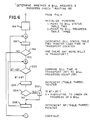
Classifications
-
- B—PERFORMING OPERATIONS; TRANSPORTING
- B65—CONVEYING; PACKING; STORING; HANDLING THIN OR FILAMENTARY MATERIAL
- B65H—HANDLING THIN OR FILAMENTARY MATERIAL, e.g. SHEETS, WEBS, CABLES
- B65H29/00—Delivering or advancing articles from machines; Advancing articles to or into piles
- B65H29/58—Article switches or diverters
-
- G—PHYSICS
- G07—CHECKING-DEVICES
- G07D—HANDLING OF COINS OR VALUABLE PAPERS, e.g. TESTING, SORTING BY DENOMINATIONS, COUNTING, DISPENSING, CHANGING OR DEPOSITING
- G07D11/00—Devices accepting coins; Devices accepting, dispensing, sorting or counting valuable papers
- G07D11/20—Controlling or monitoring the operation of devices; Data handling
- G07D11/22—Means for sensing or detection
- G07D11/235—Means for sensing or detection for monitoring or indicating operating conditions; for detecting malfunctions
- G07D11/237—Means for sensing or detection for monitoring or indicating operating conditions; for detecting malfunctions for detecting transport malfunctions, e.g. jams or misfeeds
-
- B—PERFORMING OPERATIONS; TRANSPORTING
- B65—CONVEYING; PACKING; STORING; HANDLING THIN OR FILAMENTARY MATERIAL
- B65H—HANDLING THIN OR FILAMENTARY MATERIAL, e.g. SHEETS, WEBS, CABLES
- B65H2404/00—Parts for transporting or guiding the handled material
- B65H2404/20—Belts
- B65H2404/26—Particular arrangement of belt, or belts
- B65H2404/261—Arrangement of belts, or belt(s) / roller(s) facing each other for forming a transport nip
- B65H2404/2611—Arrangement of belts, or belt(s) / roller(s) facing each other for forming a transport nip forming curved transport path
-
- B—PERFORMING OPERATIONS; TRANSPORTING
- B65—CONVEYING; PACKING; STORING; HANDLING THIN OR FILAMENTARY MATERIAL
- B65H—HANDLING THIN OR FILAMENTARY MATERIAL, e.g. SHEETS, WEBS, CABLES
- B65H2404/00—Parts for transporting or guiding the handled material
- B65H2404/20—Belts
- B65H2404/26—Particular arrangement of belt, or belts
- B65H2404/268—Arrangement of belts facing a transport surface, e.g. contact glass in copy machine
-
- B—PERFORMING OPERATIONS; TRANSPORTING
- B65—CONVEYING; PACKING; STORING; HANDLING THIN OR FILAMENTARY MATERIAL
- B65H—HANDLING THIN OR FILAMENTARY MATERIAL, e.g. SHEETS, WEBS, CABLES
- B65H2404/00—Parts for transporting or guiding the handled material
- B65H2404/60—Other elements in face contact with handled material
- B65H2404/63—Oscillating, pivoting around an axis parallel to face of material, e.g. diverting means
- B65H2404/632—Wedge member
Definitions
- This invention relates to a document dispensing system and'a a method of dispensing documents such as currency or bills in a transaction execution terminal.
- Transaction executive teminals are currently available for the performance of specific financial transactions.
- Such terminals typically require the insertion of a credit card containing account information written on a magnetic stripe and the keyboard entry of a personal ID number which corresponds in a predetermined manner to the credit card account information.
- the terminal then receives an entry of the requested amount to be withdrawn through the numeric keyboard and issues the desired amount of cash if the credit card and the ID number are found to be in order.
- One such system having the features stated in the precharacterising part of Claim 1 is described in the U.S. Patent Specification No. 3,927,925.
- control means used therewith are generally not flexible enough to handle a variety of currencies from different countries.
- the invention enables more than one document to be present in the dispensing path at any one time and provides a flexible, low-cost, accurate control of the documents being dispensed in the system.
- a document dispensing system having a dispensing path, means for feeding documents from a supply to and along said dispensing path, means located in said dispensing path for diverting said documents into either a reject bin or a customer access receptacle in response to a control signal, and a plurality of sensors positioned along said dispensing path, with at least one thereof being positioned upstream of the diverting means, said sensors being arranged to assume first and second states in accordance with the presence or absence, respectively, of said documents in said dispensing path at the locations of the sensors, characterized by storage means arranged to store a predetermined number of the most recent first and second states of the sensors to produce short-term histories of said states of each of said sensors, and also to store counts of the occurrences of one of said first and second states of each of said sensors to produce long-term histories of said one of said states of each of said sensors, each short-term and long-term history being indicative of a predetermined condition or criterion relating to
- a method of dispensing documents including the step of feeding documents along a dispensing path, characterized by the steps of sampling each of a plurality of sensors positioned along said dispensing path to produce first and second states for each sensor each time a said sensor detects the presence or absence, respectively, of one of said documents thereat, storing a predetermined number of the most recent first and second states of each of said sensors to produce short-term histories of said states of each of said sensors, and also storing counts of the occurrences of one of said first and second states of each of said sensors to provide long-term histories of said one of said states of each of said sensors, each short-term and long-term history being indicative of a predetermined condition or criterion relating to a respective document, storing status data for each of said documents derived from said short-term and long-term histories, and also storing a time in transport count for each of said documents in the dispensing path, and utilizing said status data stored for a particular document to produce a control
- Fig. 1 is a general schematic diagram of a document dispensing mechanism which may be used with this invention.
- the document dispensing mechanism which is designated generally as 20 includes a low bill hopper 22 and a high bill hopper 24 which hoppers are shown partially broken away in order to facilitate the showing thereof.
- Documents or bills such as five dollar bills in U.S. currency may be stored in the low bill hopper 22, and high bills such as a twenty dollar bill in U.S. currency may be stored in the hopper 24.
- the length of the bills is positioned from left to right, and the width thereof is aligned perpendicular to the plane of the drawing of Fig. 1.
- the bills which are present in hopper 22 are picked from the lower side thereof by the picker 26, which may be any conventional picker mechanism.
- the picker 26 which may be any conventional picker mechanism.
- the bill 28 is fed between the belts 30 and 32.
- Belt 30, for example is an endless type belt which is mounted on the pulleys 34, 36, 38, 40, 42, and 44 as shown. These pulleys 34 through 44 are supported on horizontal shafts to enable these pulleys to rotate thereon as is conventionally done.
- the belt 32 is similarly supported on pulleys 46, 48, 36, 50, 52, and 54.
- the belts 30 and 32 have teeth (not shown) thereon which are transversely located on each of the belts, and these belts engage the complementarily shaped pulleys so as to provide a positive traction for driving the belts 30 and 32.
- the bill 28, for example, which was just picked off the lower side of hopper 22, is fed between the belts 30 and 32 which form a dispensing path designated generally as 56. As the bill 28 is moved along the dispensing path by the belts 30 and 32, the bill 28 approaches a diverter means designated generally as 58.
- the diverter means 58 includes a diverter 60 which is shown in a first position in solid outline in Fig.
- the endless belt 64 is similar in construction to the endless belts 30 and 32 already described; however, the belt 64 is mounted on pulleys 71 and 72.
- the means for driving the belts 30 and 32 include a motor 74 and a conventional interconnecting means shown only as a dashed line 76.
- a conventional interconnecting means 78 is used to drivingly interconnect the pulley 70 with the driving motor 74. Because these aspects may be conventional, they need not be described in any further detail.
- the diverter 60 will be positioned in the reject position shown by a dashed outline shown in Fig. 1.
- the curved surface 84 of the diverter 60 will cause the bill approaching the diverter means 58 to be passed between the endless belt 32 and the pincher roller 82 causing the bill to fall into the reject hopper 80 which is located inside the protective cabinet 68 and which is inaccessible to a customer.
- the diverter 60 has fixed thereto a shaft 86 which is rotatably supported within the protective cabinet 68 and which shaft also has one end of link 88 fixed thereto, and the remaining end of link 88 is pivotally joined to the operating plunger 90 of the solenoid 92.
- One end of a spring 94 is operatively connected to one end of link 88 as shown, and the remaining end thereof is connected to a fixed point so as to enable the diverter means 58 to channel a bill into the reject hopper whenever the solenoid 92 is deenergized.
- Energizing the solenoid 92 causes the diverter means 58 to eject a bill into the customer receptacle 70.
- the motor 74 is operatively connected to a conventional rotary drive line 96 by a conventional interconnecting means 98 shown only as a dashed line in Fig. 1. As the motor 74 rotates, it causes the drive line 96 to rotate therewith.
- a conventional rotary clutch means 100 is mounted on the drive line 96 so as to be actuated thereby whenever the rotary clutch means 100 is to be energized.
- the rotary clutch means 100 will be energized causing the picker 26 to pick the lowermost bill from the hopper 22 as already described.
- the picker 26 has a source vacuum shown as a tube 102 connected thereto to facilitate the picking of the bill 28 from the hopper 22. Because the picker 26, drive line 96 and rotary clutch means 100 may all be conventional, they need not be described in any further detail herein.
- sensors positioned along the dispensing path. These sensors include, in the embodiment being described, a single sensor number 1 and a doubles sensor number 2, which are combined in a single unit 104 which is located at the entrance of the dispensing path 56 adjacent to the bill hopper 22.
- the sensors number 1 and number 2 are conventional photoelectric sensors which are used to detect the presence or absence of bills within the dispensing path 56.
- the sensor number 1 detects the presence of one or more bills as it approaches the dispensing path 56, and the sensor number 2 is utilized to detect those situations in which two or more bills may be together or overlapping as they are picked from the hopper 22 by the picker 26.
- a reject sensor number 3 is positioned adjacent to the entrance of the reject hopper 80 so as to detect the presence of a bill being rejected into this hopper.
- an eject sensor number 4 is positoned near the opening 66 in the protective cabinet 68 so as to be able to detect the presence of a bill such as bill 28' being dispensed into the customer receptacle 70.
- Reject sensor number 3 and eject sensor number 4 are conventional photoelectric or contact sensors which are used to detect the presence or absence of a bill in their respective areas.
- Fig. 1 What has been described so far in relation to Fig. 1 relates to the dispensing mechanism 20 for dispensing low-denomination bills from hopper 22. As is customary with cash dispensing mechanisms, provision is made for dispensing bills of a higher denomination.
- the dispensing mechanism for dispensing bills from the high bill hopper 24 is identical to that already described therefore, a complete description of all the elements included in the dispensing mechanism designated as 105 is not deemed necessary.
- the dispensing mechanism 105 for dispensing the bills from hopper 24 includes a separate picker 106 which is driven by a separate rotary clutch means 108 as shown in Fig. 1.
- the picker 106 When the rotary clutch means 108 is energized, the picker 106 will pick the lowermost bill from the high bill hopper 24 and transfer the bill so picked into a dispensing path 110 which is identical to the dispensing path 56 already described; however, the dispensing path 110 is not shown in Fig. 1.
- the dispensing mechanism 105 is located behind the dispensing mechanism 20 shown in Fig. 1.
- the dispensing mechanism 105 would have its own diverter means (similar to diverter means 58) associated therewith and it would also have the sensors number 1 through 4 located at the same points along the associated dispensing path 110.
- Fig. 2 is a general schematic diagram in block form of a control means 112 which may be used with this invention.
- the control means 112 includes a high level controller 114 which is connected to a communications driver 116 via a conventional four wire serial transmission line 118.
- the control means 112 also includes an operating system including a conventional time manager shown in block 120 of Fig. 2.
- the control means 112 also includes the cash dispenser driver 122, the magnetic card driver 124, the printer driver 126, the depository driver 128, the keyboard driver 130, the status panel driver 131 and the display driver 132. All the drivers mentioned are a part of a conventional memory designated generally as 134, and this memory also includes a conventional ROM unit 136, and a conventional read/write RAM memory 138.
- the various drivers included in the memory 134 are interconnected to a general microprocessor 140 via a conventional tri-state bus 142 as shown in Fig. 2.
- a conventional timer 144 such as integrated circuit chip # 8253 (manufactured by Intel) is also connected to the tri-state bus 142 and the processor 140.
- the various drivers shown in memory 134 in Fig. 2 are connected to their associated hardware elements by a plurality of I/O ports 146 through 158 as shown.
- the dispensing mechanism 20 shown in Fig. 1 is represented on Fig. 2 by the block 160.
- the dispensing mechanism 20 is connected via the I/O port 146 and the tri-state bus 142 to the cash dispenser driver 122 as is conventionally done.
- the transaction execution terminal with which this invention may be used is not shown in the drawing; however, the various elements associated with such a terminal are shown in block form in Fig. 2. These elements include a depository 162, a printer 164, a magnetic card reader 166, a keyboard 168, and a display 170. Because these elements are conventional, they need not be described in any further detail other than to say that the depository 162, for example, is utilized to receive deposits by a user of the transaction execution terminal. The method of using the transaction execution terminal is also conventional and need not be described in elaborate detail herein.
- Fig. 3 shows an operating system which performs several routine operations in preparation for effecting a cash dispensing function.
- the high level controller 114 shown in Fig. 2 performs the routine initialization shown at step 173 on Fig. 3.
- a user of the transaction execution terminal is requested by the display 170 to insert his magnetic card into the magnetic card reader 166 shown in Fig. 2 and also shown as step 175 in Fig. 3.
- the user enters on the keyboard 168 a secret code peculiar only to him.
- the operating system 120 controlled by the high level controller 114 then performs at step 180 a check on the authenticity of the magnetic card and the secret code entered by the user. Assuming that the magnetic card and the secret code are authentic, the display 170 requests the amount of cash which the customer wishes to receive; this is shown at step 182. At step 184, the high level controller 114 then verifies the user's account to ascertain that there is a sufficient balance therein to enable the user to be dispensed the amount of cash which was requested. At step 186 the operating system under the control of the high level controller 114 then determines the number of low amount bills and high amount bills which are to be dispensed for the amount requested by the user. At step 188, the dispensing routine is initiated.
- the cash dispensing routine is under the control of the cash dispenser driver 122 shown in Fig. 2. It should be noted at this time that there are duplicate sections in the driver 122 for the low amount bills and the high amount bills; however, the discussion will proceed with only the functions as they relate to the the low amount bills.
- the cash dispenser driver 122 shown in Fig. 2 is shown in expanded form in the chart shown in Fig. 4 so as to indicate the various subroutines which are included in the cash dispenser driver 122.
- This Routine 174 performs general housekeeping functions, such as starting the motor 74 shown in Fig. 1 and clearing various counters to be described later herein.
- the Initiate Dispensing Routine 174 also causes the time manager shown in the operating system 120 of Fig. 2 to initiate the Scan Timer Routine 176 shown in Fig. 4.
- the Routine 176 gains control from the time manager every ten milliseconds to perform its routine in the embodiment being described.
- the Scan Timer Routine 176 also initiates the Read State Of Sensors Routine 178 which reads the states of the Sensors Numbers 1 through 4 which are shown in Fig. 1.
- the Short-Term History consists of an 8-bit byte. If, for example, the first time that the Single Sensor Number 1 is read or polled and a bill such as 28 in Fig. 1 is located thereunder, a binary 1 will be recorded in the Short-Term History. If no bill is present under the Single Sensor Number 1, a binary 0 will be recorded in the Short-Term History. In the embodiment being described, this Short-Term History is stored in an 8-bit shift register, and a suitable section in memory 138. For each polling of Sensor Number 1, the most recent binary bit derived from Sensor Number 1 is fed into the rightmost position of the Short-Term History.
- the most recent 8 statuses of the Sensor Number 1 will be recorded under the Short-Term History with the most recent state of the Sensor Number 1 being located in the rightmost bit in the Table 1. This same technique is used for the Doubles Sensor Number 2, the Exit Sensor Number 3, and the Reject Sensor Number 4.
- a binary count of 1 will be added to a counter which comprises the Long-Term History shown in Table 1.
- a 0 is added to the counter which comprises the Long-Term History. Because the bill such as 28 travels at a constant rate through the dispensing path 56 shown in Fig. 1, the Long-Term History count shown in Table 1 can be used as a measure of the length of the bill passing under the Single Sensor Number 1.
- a bill progress check is made on the specific bill such as 28 in the dispensing path 56, a bill which has too high a count indicates that the bill is too long and should be diverted into the reject hopper 80 shown in Fig. 1.
- Table 2 shows a Bill Status Table which has entries for Bills Numbers 1 through 4 which may be present in the dispensing path 56 in the embodiment being described.
- the time in transport (BT) shown in the first column in Table 2 represents the actual time that a particular bill is within the dispensing path 56.
- the second column shown in Table 2 relates to the status of each of the bills.
- There is an 8-bit byte which is provided for each of the bills within the dispensing path 56 to record various states or conditions relative to that particular bill.
- the Time In Transport and th status of each bill are recorded for each of the bills such as Bills Numbers 1 through 4 in th dispensing path 56. While Bill Number 4 is shown as an entry in Table 2, generally only three bills are handled within the dispensing path 56 for the embodiment being described.
- the Bill Status Table (Table 2) is stored in a portion of the RAM memory 138 shown in Fig. 2.
- Table 3 shows a Bill Progress Table which is utilized to check on the progress of each of the bills as it travels through the dispensing path 56.
- the first column in Table 3 entitled "Progress Count” (BP) relates to binary counts which are correlated to the progress of the bills 28 as they progress through the dispensing mechanism 20.
- the first checkpoint 1 would have a progress count of 000001 1 which would indicate that this particular checkpoint is a predetermined point in the path of bill movement which is close to the Single Sensor Number 1 shown in Fig. 1.
- the progress counts are compared with the actual time in transport shown in Table 2 in order to check on the progress of the bills 28 as they progress through the dispensing mechanism 20.
- each of the Checkpoints 1 through 6 shown in Table 3 is an address of a routine which is utilized to check on the progress of the bill.
- a detailed program listing of the routines associated with the addresses shown in Table 3 is shown in the Bill Progress Check Routines listed in Table 4.
- the Initiate Dispensing Rutine 174 (Fig. 4) initiates the Read State of Sensor Routine 178 which is shown in detail in Fig. 5.
- the Routine 178 performs the function of updating the Short-Term and Long-Term Histories shown in Table 1.
- the first step 181 in the Routine 178 shown in Fig. 5 is to read a sensor port and condition the various bits and initialize loop counters associated therewith. Each of the states of the Sensors Numbers 1 through 4 is read at the same time in step 181.
- the sensor port value is rotated, putting the state of the next sensor into the carry flag.
- step 185 the old Short-Term History byte is loaded and the carry flag is rotated into the byte right-to-left, then the new Short-Term History byte is recorded in Table 1.
- the carry flag is restored in step 187.
- the old Long-Term History count and the carry flag from step 187 are added together, and then this combined count is stored in step 189 as a new Long-Term History count in Table 1.
- step 191 the question, "Have all Sensors Numbers 1 through 4 been processed?" is ascertained. If the answer is no, the routine branches back to step A to repeat the process for updating the Sensors Numbers 2 through 4. If all of the sensors have been processed at step 191, the Routine 178 is finished and the control shifts back to the Scan Timer Routine 176 shown in Fig. 4. A detailed listing of the Read State of Sensors Routine 178 is shown in Table 5.
- the microprocessor 140 shown in Fig. 2, and utilized with this invention is an 8080 Intel microprocessor, although other equivalent processors may be used with the system. Accordingly, the various operational codes and machine executable instructions shown in Table 5 and the other figures showing detailed program listings are for the 8080 microprocessor. For a more detailed description of the various operational codes, operands and the like, reference may be had to the instruction book entitled, "8080 Microcomputer Systems Users Manual", which was published by Intel Manufacturing Company, in September, 1975.
- the Scan Timer Routine 176 shown in Fig. 4 initiates the Routine 192, shown in Fig. 4 and entitled, "Determine Whether A Bill Requires A Progress Check Routine".
- This Routine 192 is shown as a flowchart in Fig. 6 and in a detail program listing in Table 6.
- the general purpose of this Routine 192 is to compare the time in transport shown in Table 2 to the various progress counts shown in Table 3.
- the Routine 192 shown in Fig. 6 the first step 194 shown therein is to initialize the pointers as shown.
- the Table 2 pointer is incremented, and the Time In Transport (BT) from Table 2 is loaded.
- the question, "Are there any more bills in transport?" is posed. If the answer to step 198 is Yes, the routine proceeds to step 200, where a comparison is made between the Time In Transport (BT) for a particular bill coming from Table 2 with one of the progress counts located in Table 3. If the Time In Transport or (BT) is less than the bill Progress Count (BP), the routine branches back to point A.
- BT Time In Transport
- BP bill Progress Count
- BT is less than BP in th example being described, it indicates that the first bill in Table 2 has not as yet progressed to Checkpoint Number 1 shown in Bill Progress Table 3. If the BT is greater than or equal to BP as shown at step 202 in Fig. 6, the Table 3 pointer is incremented so as to enable the next higher checkpoint in Table 3 to be compared with the Time In Transport (BT) at step 204. If the Time In Transport BT equals the Progress Count shown in Table 3, then the appropriate subroutine indicated by S in step 208 on Fig. 6 would be initiated to check on the progress of the bill.
- BT Time In Transport
- step 204 If in step 204, BT does not equal BP, it indicates that the Time In Transport (BT) is greater than the current BP count, and accordingly the routine 192 returns to point B thereon after incrementing the BP pointer associated with Table 3 in step 206. This process is repeated until there are no more bills in the dispensing path 56 as indicated at step 198, and thereafter, the Routine 192 branches to point C thereon which enables the Scan Timer Routine 176 to perform additional functions.
- BT Time In Transport
- the Time In Transport (BT) entries which are listed in Table 2 and the Progress Count (BP) entries in Table 3 are arranged in increasing numerical order. This fact facilitates the processing of the entries by the Routine 192 shown in Fig. 6. For example, instead of comparing each of three entries for bills numbered 1 through 3 in Table 2 with 6 entries or checkpoints in Table 3, the Routine 192, shown in Fig. 6, provides an instant-type loop situation in which six entries in Table 3 and three entries in Table 2 are compared to make a total of nine comparisons instead of eighteen via some prior art technique. Another important feature associated with the Routine 192 is that this Routine makes heavy use of the Short and Long-Term Histories of the input/output sensors listed in Table 1.
- Routine 192 shown in Fig. 6 is also initiated every ten milliseconds.
- This Routine 192 does not have to poll the Sensors Numbers 1 through 4 because there is a complete history of the various states of the sensors located in Table 1.
- the various subroutines indicated by the general term "S" in step 208 of Routine 192 of Fig. 6 relate to the Bill Progress Routines for Check Points Nos. 1-6 shown in Table 4; these routines are initiated about every 70 to 200 milliseconds in the embodiment being described herein.
- Table 7 shows a detail program listing of various Timing Definitions used in conjunction with Fig. 6 and Table 6.
- the Short-Term History for the Single Sensor No. 1 results in the binary pattern of XXXX0001 as indicated, for example, in Table 1 (with the X's indicating don't care bits) it indicates that a new bill is present in the dispensing path 56.
- the Short-Term History for a double bill is indicated by the pattern XXXX X111 for the Doubles Sensor No. 2. Three consecutive binary "1 s" were selected to indicate the presence of a "double bill" because in some isolated situations, a dark spot of ink on a single bill erroneously gave an indication of a double bill.
- the Short-Term History binary bit pattern to indicate that a bill is clear of the Exit Sensor No. 3 is XXXX XX00; the same pattern exists for the Reject Sensor No. 4 to indicate that a bill is clear of the Reject Sensor No. 4.
- the Long-Term History count shown in Table 1 is simply a count of the number of times that a bill was present or sensed at each of the Sensors Nos. 1-4; in the embodiment being described, a binary one is added each time a bill was sensed at each of these Sensors.
- the binary bits shown therein are typical patterns which may be encountered for various bills within the dispensing path 56. After a new bill is detected in the dispensing path 56, a binary "1" is added to the Time In Transport count for-that particular bill each time a polling of-the Sensors Nos. 1-4 is effected. Because the dispensing mehcanism 20 (Fig. 1) moves a bill at a constant velocity through the dispensing path 56, the Time In Transport count gives an indication of the physical progress of the bill through the dispensing path 56.
- the Status Of Bill bits shown for Bills Nos. 1-3 in Table 2 simply indicate that a "bill is present" in the dispensing path 56 for each of these bills.
- the "Determine Whether A Bill Requires a Progress Check" Routine 192 shown in Fig. 6 utilizes the Time In Transport (BT) counts shown in Table 2 and the Progress Counts (BP) shown in Table 3 as previously described.
- BT Time In Transport
- BP Progress Counts
- the Time In Transport (BT) entries for Bills Nos. 1-4 shown in Table 2 and the Progress Count (BP) entries for Check Points 1-5 shown in Table 3 are arranged in ascending order. This feature allows the Routine 192 shown in Fig. 6 and Table 6 to find an exact match between the (BT) and (BP) entries with a single pass through each of the Tables 2 and 3, thereby providing an efficient means for checking on the progress of the bills in the dispensing path 56. Once a match between the (BT) and (BP) entries is found, the jump instruction associated with the (BP) count in Table 3 is utilized to transfer control to the appropriate check routines for Check Points 1-6.
- the detail listing of the routine associated with the jump instruction FWFU ⁇ associated with the (BP) Count for Check Point 1 in Table 3 is shown in Table 8.
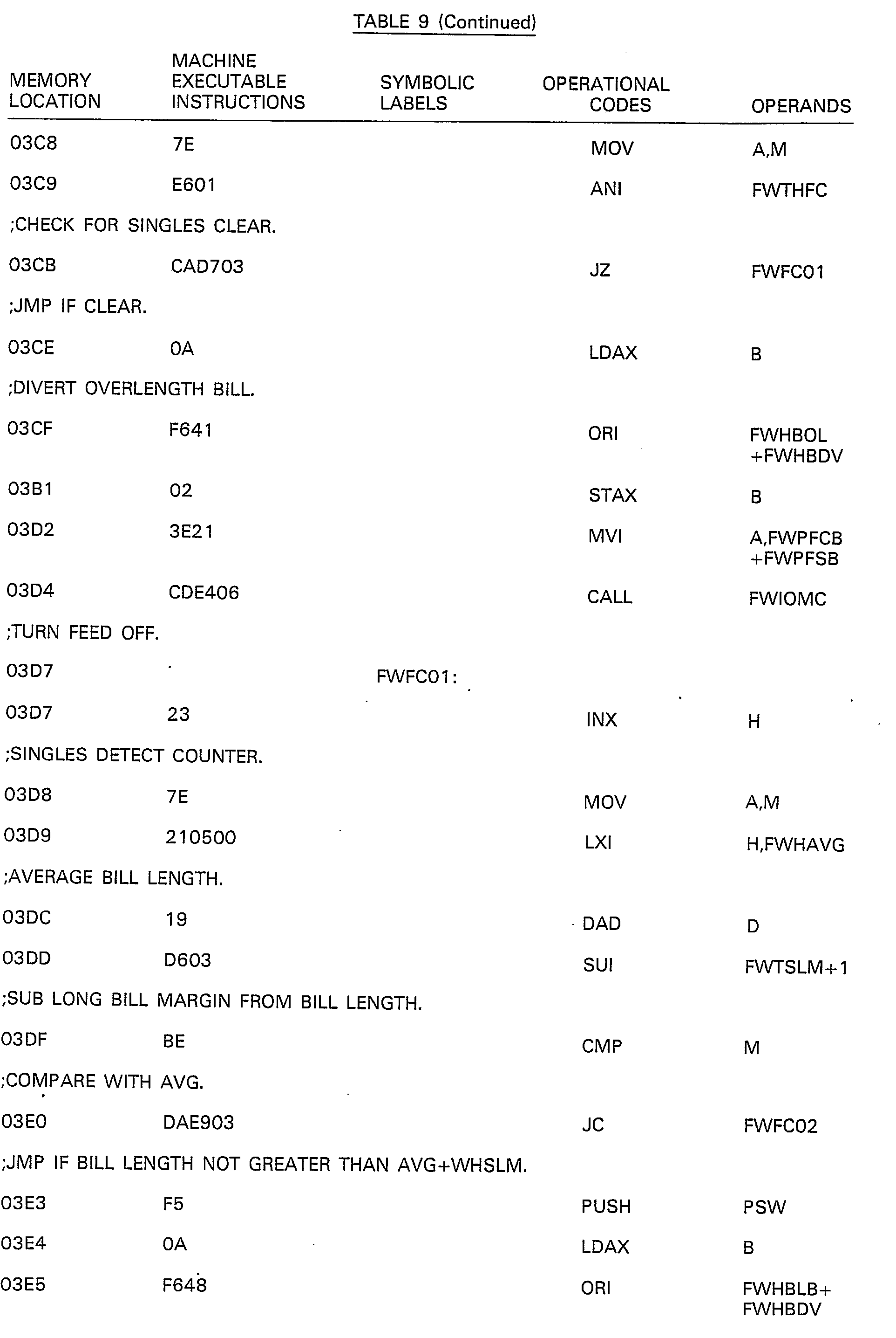
- the detail listing of the routine FWFC ⁇ for Check Point 2 is shown in Table 9.
- the detail listing of the routine FWDC00 for Check Point 3 is shown in Table 10.
- the detail listing of the routine FWXU ⁇ for Check Point 4 is shown in Table 11.
- the detail listing of the routine FWXC ⁇ for Check Point 5 is shown in Table 12; and the detail listing of the routine FWRO ⁇ for Check Point 6 is shown in Table 13.
- the Short Term and Long Term Histories from Table 1 are utilized in varying degrees in the routines associated with Check Points 1-6 enumerated in the previous paragraph. For example, from the Routine FWFU ⁇ for Check Point 1 shown in the detail listing in Table 8, if a bill being examined is too short, an operand FWHBSB as shown on the line listing for Memory Location 03A5 would indicate the Status Code for that particular bill, the definitions of the various Bill Status Codes being shown in Table 14.
- a bill length of 174 millimeters is the longest bill length that was anticipated to be dispensed by the dispensing mechanisms 20 and 104; this length is sufficient for handling U.S. and most foreign currencies.
- the average velocity of a bill 28 being fed in the dispensing path 56 is between a maximum velocity of .961 millimeters per millisecond and a minimum velocity of .835 millimeters per millisecond.
- the usual transaction receipt is routinely printed in step 210 in Fig. 3, and additional customer transaction requests may be satisfied, conventionally, in step 212 in Fig. 3 along with the updating of the associated files.
- the document dispensing system and method of this invention find their application, for instance, in the dispensing of currency or bank notes in automatic teller machines or transaction execution terminals.
Landscapes
- Physics & Mathematics (AREA)
- General Physics & Mathematics (AREA)
- Engineering & Computer Science (AREA)
- Mechanical Engineering (AREA)
- Financial Or Insurance-Related Operations Such As Payment And Settlement (AREA)
- Separation, Sorting, Adjustment, Or Bending Of Sheets To Be Conveyed (AREA)
- Controlling Sheets Or Webs (AREA)
Abstract
Description
- This invention relates to a document dispensing system and'a a method of dispensing documents such as currency or bills in a transaction execution terminal.
- Transaction executive teminals are currently available for the performance of specific financial transactions. Such terminals typically require the insertion of a credit card containing account information written on a magnetic stripe and the keyboard entry of a personal ID number which corresponds in a predetermined manner to the credit card account information. The terminal then receives an entry of the requested amount to be withdrawn through the numeric keyboard and issues the desired amount of cash if the credit card and the ID number are found to be in order. One such system having the features stated in the precharacterising part of
Claim 1 is described in the U.S. Patent Specification No. 3,927,925. - One problem associated with such transaction execution terminals is that the document or bill dispensing system associated with the terminal is generally expensive to manufacture. Also, generally only one bill at a time may be present in the bill dispensing system which makes the total time for dispensing a large number of bills time-consuming.
- Another problem associated with the document dispensing systems is that the control means used therewith are generally not flexible enough to handle a variety of currencies from different countries.
- The invention enables more than one document to be present in the dispensing path at any one time and provides a flexible, low-cost, accurate control of the documents being dispensed in the system.
- Thus, according to the invention, there is provided a document dispensing system having a dispensing path, means for feeding documents from a supply to and along said dispensing path, means located in said dispensing path for diverting said documents into either a reject bin or a customer access receptacle in response to a control signal, and a plurality of sensors positioned along said dispensing path, with at least one thereof being positioned upstream of the diverting means, said sensors being arranged to assume first and second states in accordance with the presence or absence, respectively, of said documents in said dispensing path at the locations of the sensors, characterized by storage means arranged to store a predetermined number of the most recent first and second states of the sensors to produce short-term histories of said states of each of said sensors, and also to store counts of the occurrences of one of said first and second states of each of said sensors to produce long-term histories of said one of said states of each of said sensors, each short-term and long-term history being indicative of a predetermined condition or criterion relating to a respective document, said storage means being arranged to store status data for each of said documents derived from said short term and long-term histories and also to store a time in transport count for each of said documents in the dispensing path, and processor means for producing a control signal for each document at a predetermined time during its transport in the dispensing path to control the diverting of said document either into said customer receptacle or said reject bin depending upon the status data for that document stored in said storage means.
- According to another aspect of the invention, there is provided a method of dispensing documents including the step of feeding documents along a dispensing path, characterized by the steps of sampling each of a plurality of sensors positioned along said dispensing path to produce first and second states for each sensor each time a said sensor detects the presence or absence, respectively, of one of said documents thereat, storing a predetermined number of the most recent first and second states of each of said sensors to produce short-term histories of said states of each of said sensors, and also storing counts of the occurrences of one of said first and second states of each of said sensors to provide long-term histories of said one of said states of each of said sensors, each short-term and long-term history being indicative of a predetermined condition or criterion relating to a respective document, storing status data for each of said documents derived from said short-term and long-term histories, and also storing a time in transport count for each of said documents in the dispensing path, and utilizing said status data stored for a particular document to produce a control signal at a predetermined time during the transport of said document in the dispensing path to control the diverting of said document either into a customer receptacle or a reject bin.
- One embodiment of the invention will now be described by way of example, with reference to the accompanying drawings, in which:
- Fig. 1 is a schematic diagram of a document dispensing mechanism which may be used in the dispensing system of this invention;
- Fig. 2 is a general schematic diagram in block form of a control means which may be used in the dispensing system of this invention;
- Fig. 3 is a general flow chart showing various operational steps associated with the control means shown in Fig. 2;
- Fig. 4 is a chart showing how the cash dispensing driver shown in Fig. 2 is further divided into its component routines;
- Fig. 5 is a flow chart showing a "Read State of Sensors" routine which is associated with the control means shown in Fig. 2; and
- Fig. 6 is a flow chart showing a "Determine Whether A Bill Requires A Progress Check" routine associated with the control means shown in Fig. 2.
- Fig. 1 is a general schematic diagram of a document dispensing mechanism which may be used with this invention. The document dispensing mechanism which is designated generally as 20 includes a
low bill hopper 22 and ahigh bill hopper 24 which hoppers are shown partially broken away in order to facilitate the showing thereof. Documents or bills such as five dollar bills in U.S. currency may be stored in thelow bill hopper 22, and high bills such as a twenty dollar bill in U.S. currency may be stored in thehopper 24. As shown in Fig. 1, the length of the bills is positioned from left to right, and the width thereof is aligned perpendicular to the plane of the drawing of Fig. 1. The bills which are present inhopper 22 are picked from the lower side thereof by thepicker 26, which may be any conventional picker mechanism. As a bill is picked from the lower side of thehopper 22, such asbill 28 shown only partially in Fig. 1, thebill 28 is fed between thebelts Belt 30, for example, is an endless type belt which is mounted on thepulleys belt 32 is similarly supported onpulleys belts belts - The
bill 28, for example, which was just picked off the lower side ofhopper 22, is fed between thebelts bill 28 is moved along the dispensing path by thebelts bill 28 approaches a diverter means designated generally as 58. The diverter means 58 includes adiverter 60 which is shown in a first position in solid outline in Fig. 1 which enables the bill approaching the diverter means 58 to be diverted by thecurved surface 62 of thediverter 60, causing that particular bill to be moved between theendless belt 30 and a thirdendless belt 64 and to be output through an opening 66 in theprotective cabinet 68 to thereby enable the bill shown as 28' to be dispensed into acustomer receptacle 70 which may be accessed by a customer from the exterior of theprotective cabinet 68. - The
endless belt 64 is similar in construction to theendless belts belt 64 is mounted onpulleys belts motor 74 and a conventional interconnecting means shown only as a dashed line 76. Similarly, a conventional interconnecting means 78 is used to drivingly interconnect thepulley 70 with thedriving motor 74. Because these aspects may be conventional, they need not be described in any further detail. - If for one reason or another, the
bill 28 shown in Fig. 1 is to be rejected and placed in thereject hopper 80, thediverter 60 will be positioned in the reject position shown by a dashed outline shown in Fig. 1. When in this reject position, thecurved surface 84 of thediverter 60 will cause the bill approaching the diverter means 58 to be passed between theendless belt 32 and thepincher roller 82 causing the bill to fall into thereject hopper 80 which is located inside theprotective cabinet 68 and which is inaccessible to a customer. - The
diverter 60 has fixed thereto ashaft 86 which is rotatably supported within theprotective cabinet 68 and which shaft also has one end oflink 88 fixed thereto, and the remaining end oflink 88 is pivotally joined to theoperating plunger 90 of thesolenoid 92. One end of aspring 94 is operatively connected to one end oflink 88 as shown, and the remaining end thereof is connected to a fixed point so as to enable the diverter means 58 to channel a bill into the reject hopper whenever thesolenoid 92 is deenergized. Energizing thesolenoid 92 causes the diverter means 58 to eject a bill into thecustomer receptacle 70. - The
motor 74 is operatively connected to a conventionalrotary drive line 96 by a conventional interconnecting means 98 shown only as a dashed line in Fig. 1. As themotor 74 rotates, it causes thedrive line 96 to rotate therewith. A conventional rotary clutch means 100 is mounted on thedrive line 96 so as to be actuated thereby whenever the rotary clutch means 100 is to be energized. When abill 28 is to be picked off the bottom side of thebill hopper 22, for example, the rotary clutch means 100 will be energized causing thepicker 26 to pick the lowermost bill from thehopper 22 as already described. Thepicker 26 has a source vacuum shown as atube 102 connected thereto to facilitate the picking of thebill 28 from thehopper 22. Because thepicker 26,drive line 96 and rotary clutch means 100 may all be conventional, they need not be described in any further detail herein. - In order to check on the progress of a bill such as 28 shown in Fig. 1 as it progresses through the
dispensing path 56, there are certain sensors positioned along the dispensing path. These sensors include, in the embodiment being described, asingle sensor number 1 and adoubles sensor number 2, which are combined in asingle unit 104 which is located at the entrance of thedispensing path 56 adjacent to thebill hopper 22. In the embodiment being described, thesensors number 1 andnumber 2 are conventional photoelectric sensors which are used to detect the presence or absence of bills within thedispensing path 56. Thesensor number 1 detects the presence of one or more bills as it approaches thedispensing path 56, and thesensor number 2 is utilized to detect those situations in which two or more bills may be together or overlapping as they are picked from thehopper 22 by thepicker 26. Areject sensor number 3 is positioned adjacent to the entrance of thereject hopper 80 so as to detect the presence of a bill being rejected into this hopper. Similarly, aneject sensor number 4 is positoned near the opening 66 in theprotective cabinet 68 so as to be able to detect the presence of a bill such as bill 28' being dispensed into thecustomer receptacle 70. Rejectsensor number 3 andeject sensor number 4 are conventional photoelectric or contact sensors which are used to detect the presence or absence of a bill in their respective areas. - What has been described so far in relation to Fig. 1 relates to the
dispensing mechanism 20 for dispensing low-denomination bills fromhopper 22. As is customary with cash dispensing mechanisms, provision is made for dispensing bills of a higher denomination. The dispensing mechanism for dispensing bills from thehigh bill hopper 24 is identical to that already described therefore, a complete description of all the elements included in the dispensing mechanism designated as 105 is not deemed necessary. The dispensing mechanism 105 for dispensing the bills fromhopper 24 includes aseparate picker 106 which is driven by a separate rotary clutch means 108 as shown in Fig. 1. When the rotary clutch means 108 is energized, thepicker 106 will pick the lowermost bill from thehigh bill hopper 24 and transfer the bill so picked into a dispensing path 110 which is identical to the dispensingpath 56 already described; however, the dispensing path 110 is not shown in Fig. 1. The dispensing mechanism 105 is located behind thedispensing mechanism 20 shown in Fig. 1. The dispensing mechanism 105 would have its own diverter means (similar to diverter means 58) associated therewith and it would also have thesensors number 1 through 4 located at the same points along the associated dispensing path 110. - Fig. 2 is a general schematic diagram in block form of a control means 112 which may be used with this invention. The control means 112 includes a
high level controller 114 which is connected to acommunications driver 116 via a conventional four wireserial transmission line 118. The control means 112 also includes an operating system including a conventional time manager shown inblock 120 of Fig. 2. The control means 112 also includes thecash dispenser driver 122, themagnetic card driver 124, theprinter driver 126, thedepository driver 128, thekeyboard driver 130, thestatus panel driver 131 and thedisplay driver 132. All the drivers mentioned are a part of a conventional memory designated generally as 134, and this memory also includes aconventional ROM unit 136, and a conventional read/write RAM memory 138. The various drivers included in thememory 134 are interconnected to ageneral microprocessor 140 via a conventionaltri-state bus 142 as shown in Fig. 2. Aconventional timer 144 such as integrated circuit chip #8253 (manufactured by Intel) is also connected to thetri-state bus 142 and theprocessor 140. - The various drivers shown in
memory 134 in Fig. 2 are connected to their associated hardware elements by a plurality of I/O ports 146 through 158 as shown. For example, thedispensing mechanism 20 shown in Fig. 1 is represented on Fig. 2 by theblock 160. Thedispensing mechanism 20 is connected via the I/O port 146 and thetri-state bus 142 to thecash dispenser driver 122 as is conventionally done. - The transaction execution terminal with which this invention may be used is not shown in the drawing; however, the various elements associated with such a terminal are shown in block form in Fig. 2. These elements include a
depository 162, aprinter 164, amagnetic card reader 166, akeyboard 168, and adisplay 170. Because these elements are conventional, they need not be described in any further detail other than to say that thedepository 162, for example, is utilized to receive deposits by a user of the transaction execution terminal. The method of using the transaction execution terminal is also conventional and need not be described in elaborate detail herein. Thestatus panel 172 shown in Fig. 2, is connected through the I/O port 158, through thestatus panel driver 131, through theoperating system 120, and through thecommunications driver 116 to thehigh level controller 114 to indicate the status of the cash dispenser driver (too few bills inhoppers - Before proceeding with a detailed discussion of the document dispensing system of this invention, it would appear appropriate to discuss the general functioning of a transaction execution terminal in which this invention may be incorporated. In this regard, Fig. 3 shows an operating system which performs several routine operations in preparation for effecting a cash dispensing function. The
high level controller 114 shown in Fig. 2, performs the routine initialization shown atstep 173 on Fig. 3. After this routine initialization is completed, a user of the transaction execution terminal is requested by thedisplay 170 to insert his magnetic card into themagnetic card reader 166 shown in Fig. 2 and also shown asstep 175 in Fig. 3. Atstep 177, the user enters on the keyboard 168 a secret code peculiar only to him. Theoperating system 120 controlled by thehigh level controller 114 then performs at step 180 a check on the authenticity of the magnetic card and the secret code entered by the user. Assuming that the magnetic card and the secret code are authentic, thedisplay 170 requests the amount of cash which the customer wishes to receive; this is shown atstep 182. At step 184, thehigh level controller 114 then verifies the user's account to ascertain that there is a sufficient balance therein to enable the user to be dispensed the amount of cash which was requested. Atstep 186 the operating system under the control of thehigh level controller 114 then determines the number of low amount bills and high amount bills which are to be dispensed for the amount requested by the user. Atstep 188, the dispensing routine is initiated. - The cash dispensing routine is under the control of the
cash dispenser driver 122 shown in Fig. 2. It should be noted at this time that there are duplicate sections in thedriver 122 for the low amount bills and the high amount bills; however, the discussion will proceed with only the functions as they relate to the the low amount bills. - The
cash dispenser driver 122 shown in Fig. 2, is shown in expanded form in the chart shown in Fig. 4 so as to indicate the various subroutines which are included in thecash dispenser driver 122. One of the first routines which is initiated by thecash dispenser driver 122 shown in Fig. 4, is theInitiate Dispensing Routine 174. ThisRoutine 174 performs general housekeeping functions, such as starting themotor 74 shown in Fig. 1 and clearing various counters to be described later herein. TheInitiate Dispensing Routine 174 also causes the time manager shown in theoperating system 120 of Fig. 2 to initiate theScan Timer Routine 176 shown in Fig. 4. TheRoutine 176 gains control from the time manager every ten milliseconds to perform its routine in the embodiment being described. TheScan Timer Routine 176 also initiates the Read State OfSensors Routine 178 which reads the states of theSensors Numbers 1 through 4 which are shown in Fig. 1. - Before proceeding with a discussion of the Read State Of
Sensors Routine 178, it would be useful to discuss how the reading or polling of the sensors is accomplished. Each of theSensors Numbers 1 through 4 shown on Fig. 1 is ready every ten milliseconds in the embodiment being described. The various states of the sensors are recorded in an Input/Output Sensor Status Table shown in Table 1.
- For each of the
Sensors Numbers 1 throughnumber 4, there is stored a Short-Term History and a Long-Term History. The Short-Term History consists of an 8-bit byte. If, for example, the first time that theSingle Sensor Number 1 is read or polled and a bill such as 28 in Fig. 1 is located thereunder, a binary 1 will be recorded in the Short-Term History. If no bill is present under theSingle Sensor Number 1, a binary 0 will be recorded in the Short-Term History. In the embodiment being described, this Short-Term History is stored in an 8-bit shift register, and a suitable section inmemory 138. For each polling ofSensor Number 1, the most recent binary bit derived fromSensor Number 1 is fed into the rightmost position of the Short-Term History. Thus, the most recent 8 statuses of theSensor Number 1 will be recorded under the Short-Term History with the most recent state of theSensor Number 1 being located in the rightmost bit in the Table 1. This same technique is used for theDoubles Sensor Number 2, theExit Sensor Number 3, and theReject Sensor Number 4. - Each time that a bill such as 28 in Fig. 1 is present under the
Single Sensor Number 1, for example, when that particular sensor is polled, a binary count of 1 will be added to a counter which comprises the Long-Term History shown in Table 1. When there is no bill under theSensor Number 1, a 0 is added to the counter which comprises the Long-Term History. Because the bill such as 28 travels at a constant rate through the dispensingpath 56 shown in Fig. 1, the Long-Term History count shown in Table 1 can be used as a measure of the length of the bill passing under theSingle Sensor Number 1. When a bill progress check is made on the specific bill such as 28 in the dispensingpath 56, a bill which has too high a count indicates that the bill is too long and should be diverted into thereject hopper 80 shown in Fig. 1.
- Table 2 shows a Bill Status Table which has entries for
Bills Numbers 1 through 4 which may be present in the dispensingpath 56 in the embodiment being described. The time in transport (BT) shown in the first column in Table 2 represents the actual time that a particular bill is within the dispensingpath 56. The second column shown in Table 2 relates to the status of each of the bills. There is an 8-bit byte which is provided for each of the bills within the dispensingpath 56 to record various states or conditions relative to that particular bill. The Time In Transport and th status of each bill are recorded for each of the bills such asBills Numbers 1 through 4 inth dispensing path 56. WhileBill Number 4 is shown as an entry in Table 2, generally only three bills are handled within the dispensingpath 56 for the embodiment being described. Naturally, the number of bills in the dispensingpath 56 could be changed by increasing or decreasing the length of the dispensingpath 56 so as to accommodate the usual anticipated number of bills to be handled by thedispensing mechanism 20. The Bill Status Table (Table 2) is stored in a portion of theRAM memory 138 shown in Fig. 2.
- Table 3 shows a Bill Progress Table which is utilized to check on the progress of each of the bills as it travels through the dispensing
path 56. In the embodiment- being described, there are six checkpoints corresponding to locations on the path of bill movement which are used to check on the progress of thebills 28 within thedispensing mechanism 20. The first column in Table 3 entitled "Progress Count" (BP) relates to binary counts which are correlated to the progress of thebills 28 as they progress through thedispensing mechanism 20. For example, thefirst checkpoint 1 would have a progress count of 000001 1 which would indicate that this particular checkpoint is a predetermined point in the path of bill movement which is close to theSingle Sensor Number 1 shown in Fig. 1. The progress counts are compared with the actual time in transport shown in Table 2 in order to check on the progress of thebills 28 as they progress through thedispensing mechanism 20. - Associated with each of the
Checkpoints 1 through 6 shown in Table 3, is an address of a routine which is utilized to check on the progress of the bill. A detailed program listing of the routines associated with the addresses shown in Table 3 is shown in the Bill Progress Check Routines listed in Table 4.

- For example, from Table 3, the address of the routine for
Checkpoint Number 1 is FWFU00, which is listed under the column "Operands" in Table 4. CheckPoint Number 1 is used as a check on the "Bill Under First Sensor" routine. A discussion of theCheckpoint Numbers 1 through 6 shown in Table 3 will be provided later herein. - The Initiate Dispensing Rutine 174 (Fig. 4) initiates the Read State of
Sensor Routine 178 which is shown in detail in Fig. 5. TheRoutine 178 performs the function of updating the Short-Term and Long-Term Histories shown in Table 1. Thefirst step 181 in theRoutine 178 shown in Fig. 5 is to read a sensor port and condition the various bits and initialize loop counters associated therewith. Each of the states of theSensors Numbers 1 through 4 is read at the same time instep 181. Atstep 183, the sensor port value is rotated, putting the state of the next sensor into the carry flag. Atstep 185, the old Short-Term History byte is loaded and the carry flag is rotated into the byte right-to-left, then the new Short-Term History byte is recorded in Table 1. The carry flag is restored instep 187. The old Long-Term History count and the carry flag fromstep 187 are added together, and then this combined count is stored instep 189 as a new Long-Term History count in Table 1. Atstep 191, the question, "Have allSensors Numbers 1 through 4 been processed?" is ascertained. If the answer is no, the routine branches back to step A to repeat the process for updating theSensors Numbers 2 through 4. If all of the sensors have been processed atstep 191, theRoutine 178 is finished and the control shifts back to theScan Timer Routine 176 shown in Fig. 4. A detailed listing of the Read State ofSensors Routine 178 is shown in Table 5.

- In the embodiment being described, the
microprocessor 140 shown in Fig. 2, and utilized with this invention, is an 8080 Intel microprocessor, although other equivalent processors may be used with the system. Accordingly, the various operational codes and machine executable instructions shown in Table 5 and the other figures showing detailed program listings are for the 8080 microprocessor. For a more detailed description of the various operational codes, operands and the like, reference may be had to the instruction book entitled, "8080 Microcomputer Systems Users Manual", which was published by Intel Manufacturing Company, in September, 1975. - The
Scan Timer Routine 176 shown in Fig. 4 initiates theRoutine 192, shown in Fig. 4 and entitled, "Determine Whether A Bill Requires A Progress Check Routine". ThisRoutine 192 is shown as a flowchart in Fig. 6 and in a detail program listing in Table 6. The general purpose of thisRoutine 192 is to compare the time in transport shown in Table 2 to the various progress counts shown in Table 3.


- With regard to the
Routine 192 shown in Fig. 6, thefirst step 194 shown therein is to initialize the pointers as shown. Atstep 196, the Table 2 pointer is incremented, and the Time In Transport (BT) from Table 2 is loaded. Atstep 198, the question, "Are there any more bills in transport?" is posed. If the answer to step 198 is Yes, the routine proceeds to step 200, where a comparison is made between the Time In Transport (BT) for a particular bill coming from Table 2 with one of the progress counts located in Table 3. If the Time In Transport or (BT) is less than the bill Progress Count (BP), the routine branches back to point A. If BT is less than BP in th example being described, it indicates that the first bill in Table 2 has not as yet progressed toCheckpoint Number 1 shown in Bill Progress Table 3. If the BT is greater than or equal to BP as shown atstep 202 in Fig. 6, the Table 3 pointer is incremented so as to enable the next higher checkpoint in Table 3 to be compared with the Time In Transport (BT) atstep 204. If the Time In Transport BT equals the Progress Count shown in Table 3, then the appropriate subroutine indicated by S instep 208 on Fig. 6 would be initiated to check on the progress of the bill. If instep 204, BT does not equal BP, it indicates that the Time In Transport (BT) is greater than the current BP count, and accordingly the routine 192 returns to point B thereon after incrementing the BP pointer associated with Table 3 instep 206. This process is repeated until there are no more bills in the dispensingpath 56 as indicated atstep 198, and thereafter, the Routine 192 branches to point C thereon which enables theScan Timer Routine 176 to perform additional functions. - The Time In Transport (BT) entries which are listed in Table 2 and the Progress Count (BP) entries in Table 3 are arranged in increasing numerical order. This fact facilitates the processing of the entries by the
Routine 192 shown in Fig. 6. For example, instead of comparing each of three entries for bills numbered 1 through 3 in Table 2 with 6 entries or checkpoints in Table 3, theRoutine 192, shown in Fig. 6, provides an instant-type loop situation in which six entries in Table 3 and three entries in Table 2 are compared to make a total of nine comparisons instead of eighteen via some prior art technique. Another important feature associated with theRoutine 192 is that this Routine makes heavy use of the Short and Long-Term Histories of the input/output sensors listed in Table 1. The polling of the sensors is done every ten milliseconds, and theRoutine 192 shown in Fig. 6 is also initiated every ten milliseconds. ThisRoutine 192 does not have to poll theSensors Numbers 1 through 4 because there is a complete history of the various states of the sensors located in Table 1. The various subroutines indicated by the general term "S" instep 208 ofRoutine 192 of Fig. 6 relate to the Bill Progress Routines for Check Points Nos. 1-6 shown in Table 4; these routines are initiated about every 70 to 200 milliseconds in the embodiment being described herein. - Table 7 shows a detail program listing of various Timing Definitions used in conjunction with Fig. 6 and Table 6.


- The handling of data in the Tables 1-3, alluded to earlier herein, will now be discussed in detail.
- If the Short-Term History for the Single Sensor No. 1 results in the binary pattern of XXXX0001 as indicated, for example, in Table 1 (with the X's indicating don't care bits) it indicates that a new bill is present in the dispensing
path 56. The Short-Term History for a double bill is indicated by the pattern XXXX X111 for the Doubles Sensor No. 2. Three consecutive binary "1 s" were selected to indicate the presence of a "double bill" because in some isolated situations, a dark spot of ink on a single bill erroneously gave an indication of a double bill. The Short-Term History binary bit pattern to indicate that a bill is clear of the Exit Sensor No. 3 is XXXX XX00; the same pattern exists for the Reject Sensor No. 4 to indicate that a bill is clear of the Reject Sensor No. 4. - The Long-Term History count shown in Table 1 is simply a count of the number of times that a bill was present or sensed at each of the Sensors Nos. 1-4; in the embodiment being described, a binary one is added each time a bill was sensed at each of these Sensors.
- With regard to Table 2, the binary bits shown therein are typical patterns which may be encountered for various bills within the dispensing
path 56. After a new bill is detected in the dispensingpath 56, a binary "1" is added to the Time In Transport count for-that particular bill each time a polling of-the Sensors Nos. 1-4 is effected. Because the dispensing mehcanism 20 (Fig. 1) moves a bill at a constant velocity through the dispensingpath 56, the Time In Transport count gives an indication of the physical progress of the bill through the dispensingpath 56. The Status Of Bill bits shown for Bills Nos. 1-3 in Table 2 simply indicate that a "bill is present" in the dispensingpath 56 for each of these bills. - The "Determine Whether A Bill Requires a Progress Check"
Routine 192 shown in Fig. 6 utilizes the Time In Transport (BT) counts shown in Table 2 and the Progress Counts (BP) shown in Table 3 as previously described. ForCheck Point 1 shown in Table 3, a binary count of 7 (0000 0111) and a symbolic label FWTSFU are shown therein. This label is shown under the column entitled Operands in Table 4. From what has been earlier described in relation toRoutine 192, because the (BT) count from Table 2 for Bill No. 1 is greater than the (BP) count forCheck Point 1 in Table 3, for example, the (Table 3) pointer is incremented as shown instep 202 of Fig. 6. When a (BT) count from Table 2 equals a (BP) Count from Table 3 as shown for Bill No. 3 on Table 2 andCheck Point 5 in Table 3, for example, the routine forCheck Point 5 is initiated as shown instep 208 of Fig. 6. From Table 3, the address of the routine to check on the progress of the Bill No. 3 forCheck Point 5 is shown as FWXC00. The address FWXCØØ is also shown under "Operand" for Memory Location line OOCF shown in Table 4. The symbolic Label for the (BP) label is shown forCheck Point 5 is FWTSXC, and this same label is shown under the Column "Operands" forCheck Point 5 on the listing shown in Table 4. The actual routine forCheck Point 5 to check on whether or not the bill is clear of the Exit Sensor No. 3 or the Reject Sensor No. 4 is shown in Table 12 to follow. - The Time In Transport (BT) entries for Bills Nos. 1-4 shown in Table 2 and the Progress Count (BP) entries for Check Points 1-5 shown in Table 3 are arranged in ascending order. This feature allows the
Routine 192 shown in Fig. 6 and Table 6 to find an exact match between the (BT) and (BP) entries with a single pass through each of the Tables 2 and 3, thereby providing an efficient means for checking on the progress of the bills in the dispensingpath 56. Once a match between the (BT) and (BP) entries is found, the jump instruction associated with the (BP) count in Table 3 is utilized to transfer control to the appropriate check routines for Check Points 1-6. - The detail listing of the routine associated with the jump instruction FWFUØØ associated with the (BP) Count for
Check Point 1 in Table 3 is shown in Table 8. Similarly, the detail listing of the routine FWFCØØ forCheck Point 2 is shown in Table 9. The detail listing of the routine FWDC00 forCheck Point 3 is shown in Table 10. The detail listing of the routine FWXUØØ forCheck Point 4 is shown in Table 11. The detail listing of the routine FWXCØØ forCheck Point 5 is shown in Table 12; and the detail listing of the routine FWROØØ forCheck Point 6 is shown in Table 13.




- The Short Term and Long Term Histories from Table 1 are utilized in varying degrees in the routines associated with Check Points 1-6 enumerated in the previous paragraph. For example, from the Routine FWFUØØ for
Check Point 1 shown in the detail listing in Table 8, if a bill being examined is too short, an operand FWHBSB as shown on the line listing for Memory Location 03A5 would indicate the Status Code for that particular bill, the definitions of the various Bill Status Codes being shown in Table 14.
- From Table 14 for a Symbolic Label of FWHBSB, a value of 04H (Hex Code) would be placed in a Status of Bill entry of Table 2 for that particular bill. The necessity of diverting this short bill is also shown in Table 8 on the Memory Location line 03A5 by the Operand FWHBDV, and from Table 14, the operand 40H to divert the bill would also be placed in a Status Of Bill entry of Table 2 for that particular bill. If it were earlier determined that a
particular bill 28 were too long, an eight bit status such as 0000 0001 would be placed in one of the Status of Bill entries of Table 2 to indicate that this particular bill or bills should be diverted into thereject hopper 80; this entry corresponds to Operand 01 H listed on the line corresponding to Memory Location 0001 shown in Table 14. From what has been described, the utilization of the Short Term and Long Term Histories for the routines associated with the Check Points 2-6 would appear to be self-explanatory from a reading of these routines. - A-glossary of acronyms used with various detail program listings is shown in Table 15.

- As a new bill is encountered in the dispensing
path 56, the data relative to that bill is pushed into the first entry (Bill No. 1) in Table 2, and when there are other bills in the dispensingpath 56, the data relating to these other bills is "bumped up" one entry so that the data relating to a bill which was Bill No. 1, for example, becomes Bill No. 2, etc. When a bill clears the Exit Sensor No. 3 or the Reject Sensor No. 4, all binary 0's would be placed in the last entry in Table 2, clearing the last entry, which is really Bill No. 3 because in the embodiment being described, the Bill No. 4 entry is not normally used. - In the embodiment described, a bill length of 174 millimeters is the longest bill length that was anticipated to be dispensed by the dispensing
mechanisms bill 28 being fed in the dispensingpath 56 is between a maximum velocity of .961 millimeters per millisecond and a minimum velocity of .835 millimeters per millisecond. - After the desired number of low bills and high bills is dispensed by the low
bill dispensing mechanism 20 and the highbill dispensing mechanism 104, respectively, the usual transaction receipt is routinely printed instep 210 in Fig. 3, and additional customer transaction requests may be satisfied, conventionally, instep 212 in Fig. 3 along with the updating of the associated files. - The following general summary indicates how double bills, for example, are deposited in the
reject hopper 80. When two bills in overlapping relationship enter the dispensing path 56 (Fig. 1), they are sensed by theSingle Sensor Number 1 and theDoubles Sensor Number 2. After a certain elapsed time, the leading edge of the double bills will be physically positioned nearroller 50 in the dispensingpath 56. At some point within this elapsed time, the Short Term History for the Doubles Sensor Number 2 (From Table 1) would have a typical value of 00000111. As a result of this value, the appropriate bill status codes (from Table 14) such as 02H and 40H listed under the "Operands" column would be included in Status of Bill column (Table 2) for Bill No. 1 to indicate that Bill No. 1 (the double bill in this instance) should be diverted. The "Time In Transport" (Table 2) for Bill No. 1 at this time will be approaching the value shown under the column entitled "Progress Count" for Check Point 2 (Table 3). When the Time In Transport (Table 2) for Bill No. 1 coincides with the value shown under the "Progress Count" for Check Point 2 (Table 3), a routine whose address is shown on the same line as Check Point 2 (Table 3) is initiated to check on the progress of Bill No. 1. Because the "Status of Bill" from Table 2 indicates a double bill status (Operand 02H) and also indicates that the bill should be diverted (Operand 40H) the routine mentioned (from Table 3, line 2) would produce a control signal which deenergizes the solenoid 92 (Fig. 1), permitting thespring 94 to move thediverter 60 to the position shown in dashed outline, which in turn diverts the double bills into thereject hopper 80. - When a single, "good" bill, for example, proceeds generally through the dispensing
path 56 as previously described in relation to a "double bills" situation described in the previous paragraph, the "Status Of Bill" (Table 2) for Bill No. 1 would indicate the Bill Status Code of 80H from Table 14. As the good bill progresses through the dispensing path 56 (Fig. 1), the "Time In Transport" (Table 2) for Bill No. 1 (the good bill in this instance) would be approaching the value shown under Progress Count (Table 3) forCheck Point 2. When the "Time In Transport" for Bill No. 1 equals the value shown under Progress Count forCheck Point 2, the routine having the address shown online 2 of Table 3 will be initiated. Because "Status of Bill" from Table 2 indicates that it is a "good" bill (Operand 80H), the routine will generate a control signal (opposite to that for a "defective" bill) which will energize the solenoid 92 (Fig. 1) causing thediverter 60 to assume the position shown by the solid outline, thereby directing the "good" bill to thecustomer receptacle 70. - The document dispensing system and method of this invention find their application, for instance, in the dispensing of currency or bank notes in automatic teller machines or transaction execution terminals.
Claims (8)
Applications Claiming Priority (2)
| Application Number | Priority Date | Filing Date | Title |
|---|---|---|---|
| US05/904,957 US4179031A (en) | 1978-05-11 | 1978-05-11 | Document dispensing system |
| US904957 | 1978-05-11 |
Publications (3)
| Publication Number | Publication Date |
|---|---|
| EP0016003A4 EP0016003A4 (en) | 1980-09-29 |
| EP0016003A1 EP0016003A1 (en) | 1980-10-01 |
| EP0016003B1 true EP0016003B1 (en) | 1984-07-25 |
Family
ID=25420043
Family Applications (1)
| Application Number | Title | Priority Date | Filing Date |
|---|---|---|---|
| EP79900561A Expired EP0016003B1 (en) | 1978-05-11 | 1979-12-17 | Document dispensing system and method |
Country Status (5)
| Country | Link |
|---|---|
| US (1) | US4179031A (en) |
| EP (1) | EP0016003B1 (en) |
| JP (1) | JPS55500248A (en) |
| DE (1) | DE2967126D1 (en) |
| WO (1) | WO1979001055A1 (en) |
Families Citing this family (23)
| Publication number | Priority date | Publication date | Assignee | Title |
|---|---|---|---|---|
| DE2936573A1 (en) * | 1978-09-15 | 1980-03-27 | De La Rue Crosfield | SHEET NUMBER METHOD AND DEVICE |
| US4358016A (en) * | 1979-02-21 | 1982-11-09 | Burroughs Corporation | Document sorter apparatus |
| SE430547B (en) * | 1979-07-26 | 1983-11-21 | Lundblad Leif | DEFINITION OF DOCUMENT OUTPUT |
| DE3277094D1 (en) * | 1981-03-20 | 1987-10-01 | De La Rue Syst | Cash dispensing apparatus |
| US4482057A (en) * | 1981-12-30 | 1984-11-13 | Ncr Corporation | Record media dispensing apparatus |
| US4521008A (en) * | 1983-03-03 | 1985-06-04 | Ncr Corporation | Fail safe document dispensing system |
| US4570801A (en) * | 1984-03-21 | 1986-02-18 | Brannen Ralph L | Document handling machine |
| FR2599494A1 (en) * | 1986-05-30 | 1987-12-04 | Commissariat Energie Atomique | METHOD FOR DETECTING SUPERIMPOSED SHEETS, DEVICE FOR IMPLEMENTING THE METHOD AND APPLICATION TO BANK NOTES |
| US5018720A (en) * | 1990-03-22 | 1991-05-28 | Ncr Corporation | Document transport module |
| DE59207330D1 (en) * | 1991-09-04 | 1996-11-14 | Mars Inc | Cassette for flexible sheets |
| US6293469B1 (en) | 1994-12-20 | 2001-09-25 | Dh Technology Inc. | Transaction printer |
| US7513417B2 (en) | 1996-11-15 | 2009-04-07 | Diebold, Incorporated | Automated banking machine |
| US7559460B2 (en) | 1996-11-15 | 2009-07-14 | Diebold Incorporated | Automated banking machine |
| US7584883B2 (en) | 1996-11-15 | 2009-09-08 | Diebold, Incorporated | Check cashing automated banking machine |
| US6273413B1 (en) * | 1997-11-28 | 2001-08-14 | Diebold, Incorporated | Automated banking machine with sheet directing apparatus |
| US6014594A (en) * | 1998-03-11 | 2000-01-11 | Bally Gaming, Inc. | Gaming machine payout dispensing system with on escrow area and locks |
| US6332099B1 (en) | 1998-03-11 | 2001-12-18 | Bally Gaming, Inc. | Gaming machine payout controlling system and method |
| US6293867B1 (en) | 1998-03-11 | 2001-09-25 | Bally Gaming, Inc. | Gaming machine payout system and method |
| EP1188141A4 (en) | 1999-04-23 | 2005-05-11 | Alliance Gaming Corp | SYSTEM AND METHOD FOR SAFELY STORING AND MONITORING THE ISSUE OF PAYMENT |
| WO2001059685A2 (en) * | 2000-02-08 | 2001-08-16 | Cummins-Allison Corp. | Method and apparatus for detecting doubled bills in a currency handling device |
| CA2361969A1 (en) | 2001-11-14 | 2003-05-14 | Omron Canada Inc. | A method and system for double feed detection in a letter sorting apparatus |
| JP3968399B2 (en) * | 2002-08-27 | 2007-08-29 | 旭精工株式会社 | Paper sheet feeding device |
| CN101758027B (en) * | 2009-05-11 | 2015-03-25 | 天津长荣印刷设备股份有限公司 | Removing device for printing machinery and working method thereof |
Family Cites Families (13)
| Publication number | Priority date | Publication date | Assignee | Title |
|---|---|---|---|---|
| DE1524526A1 (en) * | 1966-09-20 | 1970-07-02 | Siemens Ag | Arrangement for monitoring transport routes |
| NL7103555A (en) * | 1971-03-17 | 1972-09-19 | ||
| JPS514879B2 (en) * | 1971-09-28 | 1976-02-16 | ||
| US3949200A (en) * | 1971-10-30 | 1976-04-06 | Glory Kogyo Kabushiki Kaisha | System for selective operation of money dispensing machine |
| US3818461A (en) * | 1972-04-10 | 1974-06-18 | Litton Systems Inc | Buffer memory system |
| US3941977A (en) * | 1972-09-01 | 1976-03-02 | The Mosler Safe Company | Off-line cash dispenser and banking system |
| US3791392A (en) * | 1972-09-28 | 1974-02-12 | Pitney Bowes Inc | Currency dispenser |
| JPS5081347A (en) * | 1973-11-19 | 1975-07-02 | ||
| US3949368A (en) * | 1974-01-23 | 1976-04-06 | Data General Corporation | Automatic data priority technique |
| US3937925A (en) * | 1974-06-25 | 1976-02-10 | Ibm Corporation | Modular transaction terminal with microprocessor control |
| US3937453A (en) * | 1974-08-02 | 1976-02-10 | Docutel Corporation | Single document transport |
| JPS5272233A (en) * | 1975-12-12 | 1977-06-16 | Minolta Camera Co Ltd | Detector for paper jam in the electrophotographic copying machine |
| US4022460A (en) * | 1976-02-05 | 1977-05-10 | Pitney-Bowes, Inc. | Document jam detector for copier |
-
1978
- 1978-05-11 US US05/904,957 patent/US4179031A/en not_active Expired - Lifetime
-
1979
- 1979-05-07 WO PCT/US1979/000301 patent/WO1979001055A1/en not_active Ceased
- 1979-05-07 JP JP50081379A patent/JPS55500248A/ja active Pending
- 1979-05-07 DE DE7979900561T patent/DE2967126D1/en not_active Expired
- 1979-12-17 EP EP79900561A patent/EP0016003B1/en not_active Expired
Also Published As
| Publication number | Publication date |
|---|---|
| US4179031A (en) | 1979-12-18 |
| EP0016003A4 (en) | 1980-09-29 |
| DE2967126D1 (en) | 1984-08-30 |
| JPS55500248A (en) | 1980-04-24 |
| WO1979001055A1 (en) | 1979-12-13 |
| EP0016003A1 (en) | 1980-10-01 |
Similar Documents
| Publication | Publication Date | Title |
|---|---|---|
| US4179031A (en) | Document dispensing system | |
| EP1868167B1 (en) | Bill handling machine | |
| US4532641A (en) | Cash accounting system | |
| EP0473106B1 (en) | Banknote handling apparatus | |
| US7090121B2 (en) | Sheet handling machine | |
| US8958904B2 (en) | Banknote handling apparatus | |
| EP2503519A1 (en) | Money handling apparatus | |
| US20090260948A1 (en) | Money handling machine | |
| US5071031A (en) | Automatic cash transaction apparatus utilizing successive cash dispensing operations | |
| JPS6141439B2 (en) | ||
| CN1161719C (en) | Automatic booking machine | |
| JP4498758B2 (en) | Automatic change machine | |
| JP3956256B2 (en) | Paper sheet identification method and paper sheet identification apparatus | |
| JPS59153287A (en) | Automatic transaction equipment | |
| JP3018512B2 (en) | Coin depositing and dispensing machine | |
| JP3075560B2 (en) | Banknote handling equipment | |
| JP3107307B2 (en) | Banknote handling equipment | |
| JP2972816B2 (en) | Banknote handling equipment | |
| JP2953266B2 (en) | Coin identification device | |
| JPS60117389A (en) | Paper money sorter/settler | |
| JPS5911464A (en) | Data processor | |
| JP2972815B2 (en) | Banknote handling equipment | |
| JPS62128394A (en) | Currency processor | |
| JPS6148091A (en) | automated teller machine | |
| JPS59160288A (en) | Wrapped coin receiver |
Legal Events
| Date | Code | Title | Description |
|---|---|---|---|
| PUAI | Public reference made under article 153(3) epc to a published international application that has entered the european phase |
Free format text: ORIGINAL CODE: 0009012 |
|
| DET | De: translation of patent claims | ||
| 17P | Request for examination filed | ||
| AK | Designated contracting states |
Designated state(s): DE FR GB |
|
| GRAA | (expected) grant |
Free format text: ORIGINAL CODE: 0009210 |
|
| AK | Designated contracting states |
Designated state(s): DE FR GB |
|
| REF | Corresponds to: |
Ref document number: 2967126 Country of ref document: DE Date of ref document: 19840830 |
|
| ET | Fr: translation filed | ||
| PLBE | No opposition filed within time limit |
Free format text: ORIGINAL CODE: 0009261 |
|
| STAA | Information on the status of an ep patent application or granted ep patent |
Free format text: STATUS: NO OPPOSITION FILED WITHIN TIME LIMIT |
|
| 26N | No opposition filed | ||
| PG25 | Lapsed in a contracting state [announced via postgrant information from national office to epo] |
Ref country code: FR Free format text: LAPSE BECAUSE OF NON-PAYMENT OF DUE FEES Effective date: 19880129 |
|
| PG25 | Lapsed in a contracting state [announced via postgrant information from national office to epo] |
Ref country code: DE Effective date: 19880202 |
|
| GBPC | Gb: european patent ceased through non-payment of renewal fee | ||
| REG | Reference to a national code |
Ref country code: FR Ref legal event code: ST |
|
| PG25 | Lapsed in a contracting state [announced via postgrant information from national office to epo] |
Ref country code: GB Free format text: LAPSE BECAUSE OF NON-PAYMENT OF DUE FEES Effective date: 19881118 |