EP0015829B1 - Procédé électromagnétique pour régler l'orientation d'une plate-forme et plate-forme mettant en oeuvre ce procédé - Google Patents
Procédé électromagnétique pour régler l'orientation d'une plate-forme et plate-forme mettant en oeuvre ce procédé Download PDFInfo
- Publication number
- EP0015829B1 EP0015829B1 EP80400276A EP80400276A EP0015829B1 EP 0015829 B1 EP0015829 B1 EP 0015829B1 EP 80400276 A EP80400276 A EP 80400276A EP 80400276 A EP80400276 A EP 80400276A EP 0015829 B1 EP0015829 B1 EP 0015829B1
- Authority
- EP
- European Patent Office
- Prior art keywords
- platform
- orientation
- magnets
- electromagnetic
- plane
- Prior art date
- Legal status (The legal status is an assumption and is not a legal conclusion. Google has not performed a legal analysis and makes no representation as to the accuracy of the status listed.)
- Expired
Links
- 238000000034 method Methods 0.000 title claims abstract description 18
- 230000008569 process Effects 0.000 title description 3
- 239000004020 conductor Substances 0.000 claims description 10
- 238000006073 displacement reaction Methods 0.000 claims description 7
- 238000001514 detection method Methods 0.000 claims description 5
- 230000003321 amplification Effects 0.000 claims description 3
- 239000013013 elastic material Substances 0.000 claims description 3
- 238000003199 nucleic acid amplification method Methods 0.000 claims description 3
- 230000003750 conditioning effect Effects 0.000 claims 2
- 230000005672 electromagnetic field Effects 0.000 claims 1
- 230000007246 mechanism Effects 0.000 description 4
- 238000004804 winding Methods 0.000 description 4
- 238000012550 audit Methods 0.000 description 3
- 230000000903 blocking effect Effects 0.000 description 3
- 238000006243 chemical reaction Methods 0.000 description 2
- 230000000694 effects Effects 0.000 description 2
- 238000004146 energy storage Methods 0.000 description 2
- 238000002513 implantation Methods 0.000 description 2
- 230000004807 localization Effects 0.000 description 2
- 229910000906 Bronze Inorganic materials 0.000 description 1
- 241001080024 Telles Species 0.000 description 1
- 230000008901 benefit Effects 0.000 description 1
- 229910052790 beryllium Inorganic materials 0.000 description 1
- ATBAMAFKBVZNFJ-UHFFFAOYSA-N beryllium atom Chemical compound [Be] ATBAMAFKBVZNFJ-UHFFFAOYSA-N 0.000 description 1
- 239000010974 bronze Substances 0.000 description 1
- KUNSUQLRTQLHQQ-UHFFFAOYSA-N copper tin Chemical compound [Cu].[Sn] KUNSUQLRTQLHQQ-UHFFFAOYSA-N 0.000 description 1
- 238000013016 damping Methods 0.000 description 1
- 230000000368 destabilizing effect Effects 0.000 description 1
- 230000005520 electrodynamics Effects 0.000 description 1
- 238000010304 firing Methods 0.000 description 1
- 230000004907 flux Effects 0.000 description 1
- 230000006698 induction Effects 0.000 description 1
- 230000003993 interaction Effects 0.000 description 1
- 230000005415 magnetization Effects 0.000 description 1
- 239000000725 suspension Substances 0.000 description 1
Images


Classifications
-
- B—PERFORMING OPERATIONS; TRANSPORTING
- B64—AIRCRAFT; AVIATION; COSMONAUTICS
- B64G—COSMONAUTICS; VEHICLES OR EQUIPMENT THEREFOR
- B64G1/00—Cosmonautic vehicles
- B64G1/22—Parts of, or equipment specially adapted for fitting in or to, cosmonautic vehicles
- B64G1/24—Guiding or controlling apparatus, e.g. for attitude control
- B64G1/32—Guiding or controlling apparatus, e.g. for attitude control using earth's magnetic field
-
- B—PERFORMING OPERATIONS; TRANSPORTING
- B64—AIRCRAFT; AVIATION; COSMONAUTICS
- B64G—COSMONAUTICS; VEHICLES OR EQUIPMENT THEREFOR
- B64G1/00—Cosmonautic vehicles
- B64G1/22—Parts of, or equipment specially adapted for fitting in or to, cosmonautic vehicles
-
- H—ELECTRICITY
- H01—ELECTRIC ELEMENTS
- H01Q—ANTENNAS, i.e. RADIO AERIALS
- H01Q1/00—Details of, or arrangements associated with, antennas
- H01Q1/12—Supports; Mounting means
- H01Q1/18—Means for stabilising antennas on an unstable platform
-
- H—ELECTRICITY
- H01—ELECTRIC ELEMENTS
- H01Q—ANTENNAS, i.e. RADIO AERIALS
- H01Q1/00—Details of, or arrangements associated with, antennas
- H01Q1/27—Adaptation for use in or on movable bodies
- H01Q1/28—Adaptation for use in or on aircraft, missiles, satellites, or balloons
- H01Q1/288—Satellite antennas
Definitions
- the present invention relates to the field of platforms intended to support equipment to be oriented with precision along two axes, and it relates more particularly, on satellites in particular, to the orientation of the antennas and of flywheels intended for allow piloting.
- the invention also relates to a platform implementing the above method, which comprises: the electromagnetic devices each comprising the magnets linked to the platform which contains said reference plane; the coil mechanically linked to said fixed plane and disposed in the air gap of said magnets; the deflection detector supplying the voltage substantially proportional to said deflection, and the control and amplification chain, said reference point being subject to said fixed plane.
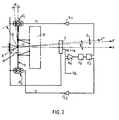
- the pivoting of the platform p takes place around the axes x, x 'and y, y', and this is made possible in the invention by the fact of the use of electromagnetic means positioned respectively on said axes in regions A1, A2 and B1, B2.
- the subjection of the point 0 substantially at the distance d can be obtained in different ways, in particular by mechanical means, which will also be better explained below.
- connection mode which allows the subjection of the point 0 has, in any event, a stiffness K which intervenes in the development of the characteristics of the servo-control determining the orientation of the platform.
- the enslavement is such that there is permanently proportionality between the error signal ⁇ measured by the detector s, after subtracting the chosen permanent depointing (which can be for example of the radio frequency type for a satellite antenna ) and the current i flowing in the windings of the electromagnetic devices A1, A2, B1 and B2.
- These electromagnetic devices implement the Laplace electrodynamic interaction between magnetic field and current passing through the windings and therefore behave like a mobile frame galvanometer produced in a linear configuration.
- the coil wires 1 are parallel to the plane p and in a direction substantially orthogonal to the axis oy.
- the coil 1 mechanically linked to the fixed plane is stuck perpendicular to the plane p in the air gaps e1, e2 of magnets 2 and 3 linked to the platform 4 containing the plane p so that, when the current i, coming from the servo and amplification chain, crosses the coil 1, the forces F1 (or F2 depending on the direction of current flow), then appearing in reaction on said magnets 2 and 3, thereby cause the plane p to rotate.
- the servo is designed so that there is permanently proportionality between the error signal ⁇ measured by the detector s and the currents i1, i2 flowing in the coils of devices A1, A2 (or currents i3, i4 flowing in the coils of devices B1, B2), it can be provided that the proportionality coefficient, which is the gain k of the control loop, is determined to ensure the accuracy of the desired pointing.
- the detector delivers a voltage vs proportional to the detected depointing angle s, which leads, for a given gain, to:
- the gain which corresponds to the proportionality coefficient between the current and the detection, can be chosen so that, for the maximum value of the rotation 0, the pointing error s is limited to the desired value.
- Figs. 8 and 9 are respectively representative of an antenna orientation system r with its deviation detector delivering the signals v's of deviation ⁇ , and possibly v'8 of permanent depointing 8, and of an orientation system axis of rotation of one or two flywheels g and c, g with or without kinetic energy storage with its deviation detector delivering the signals v " ⁇ of deviation e and possibly v" 8 of depointing 8, thus allowing the piloting of the satellite.
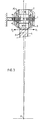
- each of the electromagnetic devices shown in FIGS. 4 and 5 and which bear the reference A "1 comprises two pairs of magnets 6, 7 secured to the platform 5 containing the plane p and these magnets straddle the coil 8 secured to the support plane parallel to the plane p.
- the coil conductors located in the air gap e1, e2 of the magnets cause, depending on the direction of current flow, forces F1 or F2 operating on the platform to cause its angular displacement.
- each of the electromagnetic devices which bear the mark A "'1 comprises an annular magnet with radial magnetization 9 closing the magnetic flux through a yoke 10 and which is integral with the platform 11 containing the plane p.
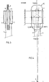
- fig. 10 represents a connecting means marked 14 and which consists of a thin cylinder made of an elastic material, such as beryllium bronze for example, and this cylinder is radially perforated with lights 14a placed in staggered rows so that small deformations resulting from the displacement of the point 0 in 0 'are suitably absorbed, while the stiffness K remains substantially constant.
- Fig. 11 shows a variant of a cylinder of the same kind 13 in which the openings 13a are arranged alternately in the radial direction, which also makes it possible to absorb the small deformations of the point O at 0 ', while here again the stiffness K remains substantially constant .
- Such means have the advantage of reliability in that the fatigue rupture of a part between the lights does not put the entire device out of service.
- the invention uses a blocking device to make the mobile part and the fixed part integral during the launch of the satellite.
- a blocking device to make the mobile part and the fixed part integral during the launch of the satellite.
- Such mechanisms are well known and are used in the space field whenever an item of equipment requires a rigid connection on a fixed structure to withstand the vibrations occurring during launch. This is the case, for example, for flywheels with magnetic suspension.
- These blocking devices are generally released using a pyrotechnic choke, the firing of which is carried out by control of the ground after the forces having required blocking have disappeared.
Landscapes
- Engineering & Computer Science (AREA)
- Remote Sensing (AREA)
- Aviation & Aerospace Engineering (AREA)
- Physics & Mathematics (AREA)
- Astronomy & Astrophysics (AREA)
- General Physics & Mathematics (AREA)
- Geology (AREA)
- Radar, Positioning & Navigation (AREA)
- General Life Sciences & Earth Sciences (AREA)
- Geochemistry & Mineralogy (AREA)
- Life Sciences & Earth Sciences (AREA)
- Chemical & Material Sciences (AREA)
- Combustion & Propulsion (AREA)
- Environmental & Geological Engineering (AREA)
- Variable-Direction Aerials And Aerial Arrays (AREA)
- Magnetic Bearings And Hydrostatic Bearings (AREA)
- Vehicle Body Suspensions (AREA)
- Forklifts And Lifting Vehicles (AREA)
- Control Of Position, Course, Altitude, Or Attitude Of Moving Bodies (AREA)
- Control Of Position Or Direction (AREA)
- Details Of Measuring And Other Instruments (AREA)
- Details Of Aerials (AREA)
Priority Applications (1)
| Application Number | Priority Date | Filing Date | Title |
|---|---|---|---|
| AT80400276T ATE1890T1 (de) | 1979-02-28 | 1980-02-27 | Elektromagnetisches verfahren zur richtungsregelung einer plattform und ein solches verfahren verwendende plattform. |
Applications Claiming Priority (2)
| Application Number | Priority Date | Filing Date | Title |
|---|---|---|---|
| FR7905283 | 1979-02-28 | ||
| FR7905283A FR2450444A1 (fr) | 1979-02-28 | 1979-02-28 | Procede electromagnetique pour regler l'orientation d'une plate-forme |
Publications (2)
| Publication Number | Publication Date |
|---|---|
| EP0015829A1 EP0015829A1 (fr) | 1980-09-17 |
| EP0015829B1 true EP0015829B1 (fr) | 1982-12-01 |
Family
ID=9222605
Family Applications (1)
| Application Number | Title | Priority Date | Filing Date |
|---|---|---|---|
| EP80400276A Expired EP0015829B1 (fr) | 1979-02-28 | 1980-02-27 | Procédé électromagnétique pour régler l'orientation d'une plate-forme et plate-forme mettant en oeuvre ce procédé |
Country Status (7)
| Country | Link |
|---|---|
| US (1) | US4325586A (enExample) |
| EP (1) | EP0015829B1 (enExample) |
| JP (1) | JPS55121107A (enExample) |
| AT (1) | ATE1890T1 (enExample) |
| CA (1) | CA1151267A (enExample) |
| DE (1) | DE3061179D1 (enExample) |
| FR (1) | FR2450444A1 (enExample) |
Families Citing this family (17)
| Publication number | Priority date | Publication date | Assignee | Title |
|---|---|---|---|---|
| FR2485275A1 (fr) * | 1979-06-18 | 1981-12-24 | Aerospatiale | Procede de pilotage d'orientation d'antenne sur un satellite et configuration de detecteurs mettant en oeuvre ce procede |
| FR2472284A1 (fr) * | 1979-12-18 | 1981-06-26 | Aerospatiale | Procede de correction de la defocalisation transversale d'un paraboloide et dispositif correspondant de correction d'antenne parabolique |
| FR2486675A1 (fr) * | 1980-07-09 | 1982-01-15 | Aerospatiale | Procede et systeme d'asservissement d'une plate-forme mobile montee a bord d'un vehicule spatial |
| FR2502404A1 (fr) * | 1981-03-20 | 1982-09-24 | Matra | Dispositif de montage articule, notamment d'un sous-ensemble de satellite artificiel |
| US4687161A (en) * | 1985-09-30 | 1987-08-18 | Ford Aerospace & Communications Corporation | Pointing compensation system for spacecraft instruments |
| US4814907A (en) * | 1987-11-24 | 1989-03-21 | Goor Associates, Inc. | Method and apparatus for maintaining constant flying height via magnetic interaction |
| US4954904A (en) * | 1987-11-24 | 1990-09-04 | Goor Associates, Inc. | Method and apparatus for preventing head crashes in a disk system |
| CA2080612A1 (en) * | 1991-11-27 | 1993-05-28 | Douglas J. Bender | Method and apparatus for compensating for magnetic disturbance torques on a satellite |
| US5228683A (en) * | 1992-04-20 | 1993-07-20 | Beimel Roger G | Baseball batters training device |
| US5441222A (en) * | 1993-04-26 | 1995-08-15 | Hughes Aircraft Company | Attitude control of spinning spacecraft |
| US6247666B1 (en) | 1998-07-06 | 2001-06-19 | Lockheed Martin Corporation | Method and apparatus for non-propulsive fin control in an air or sea vehicle using planar actuation |
| US7679245B2 (en) * | 2001-09-17 | 2010-03-16 | Beacon Power Corporation | Repulsive lift systems, flywheel energy storage systems utilizing such systems and methods related thereto |
| US6849980B1 (en) * | 2003-02-21 | 2005-02-01 | Che Ram Souza Voigt | Cross plane wide-gap motor system for gimbal |
| US20050253473A1 (en) * | 2004-05-13 | 2005-11-17 | Studer Philip A | Alternative magnetic bearing |
| FR2934677B1 (fr) * | 2008-07-29 | 2011-05-27 | Thales Sa | Dispositif d'actionneur gyroscopique a suspension magnetique |
| CN102530267B (zh) * | 2010-12-10 | 2014-09-03 | 上海卫星工程研究所 | 卫星公用平台 |
| CN104015939A (zh) * | 2014-05-26 | 2014-09-03 | 中国科学院长春光学精密机械与物理研究所 | 用于平台载荷一体化卫星的综合管理系统 |
Family Cites Families (8)
| Publication number | Priority date | Publication date | Assignee | Title |
|---|---|---|---|---|
| FR1418751A (fr) * | 1958-06-12 | 1965-11-26 | Perfectionnements à la suspension des véhicules | |
| US3230377A (en) * | 1962-03-30 | 1966-01-18 | Smith George Allan | Self-stabilized theodolite for manualtracking using photosensitive stabilizing means |
| FR1602955A (enExample) * | 1968-06-25 | 1971-03-01 | ||
| US3755656A (en) * | 1971-02-26 | 1973-08-28 | Litton Business Systems Inc | Data processing system |
| DE2213470C3 (de) * | 1972-03-20 | 1988-12-01 | Padana AG, Zug | Magnetisches Lager |
| DE2213465C3 (de) * | 1972-03-20 | 1986-02-13 | Padana AG, Zug | Elektromagnetisches Lagerelement |
| US3775656A (en) * | 1972-05-22 | 1973-11-27 | Aviat Inc | Platform stabilization system |
| US3955858A (en) * | 1974-01-03 | 1976-05-11 | Societe Nationale Industrielle Aerospatiale | Satellite momentum wheel |
-
1979
- 1979-02-28 FR FR7905283A patent/FR2450444A1/fr active Granted
-
1980
- 1980-02-27 US US06/125,058 patent/US4325586A/en not_active Expired - Lifetime
- 1980-02-27 EP EP80400276A patent/EP0015829B1/fr not_active Expired
- 1980-02-27 AT AT80400276T patent/ATE1890T1/de active
- 1980-02-27 DE DE8080400276T patent/DE3061179D1/de not_active Expired
- 1980-02-27 JP JP2393480A patent/JPS55121107A/ja active Granted
- 1980-02-28 CA CA000346660A patent/CA1151267A/en not_active Expired
Also Published As
| Publication number | Publication date |
|---|---|
| JPS55121107A (en) | 1980-09-18 |
| FR2450444B1 (enExample) | 1982-03-19 |
| FR2450444A1 (fr) | 1980-09-26 |
| DE3061179D1 (en) | 1983-01-05 |
| US4325586A (en) | 1982-04-20 |
| ATE1890T1 (de) | 1982-12-15 |
| JPS6216394B2 (enExample) | 1987-04-13 |
| EP0015829A1 (fr) | 1980-09-17 |
| CA1151267A (en) | 1983-08-02 |
Similar Documents
| Publication | Publication Date | Title |
|---|---|---|
| EP0015829B1 (fr) | Procédé électromagnétique pour régler l'orientation d'une plate-forme et plate-forme mettant en oeuvre ce procédé | |
| EP0435708B1 (fr) | Procédé de contrôle d'attitude en roulis et en lacet d'un satellite | |
| EP0576310B1 (fr) | Dispositif de mesure d'un couple de torsion sur un arbre tournant | |
| EP2810875B1 (fr) | Système de propulsion en deux modules pour contrôle d'orbite et contrôle d'attitude de satellite | |
| EP2130767B1 (fr) | Dispositif de maintien d'au moins un objet mobile, réutilisable, sécurisé autonome et sans chocs, pour engins spatiaux | |
| EP0616665A1 (fr) | Dispositif a palier magnetique et a butee mecanique pour le positionnement d'un corps tournant par rapport a un corps statorique | |
| EP0338933A1 (fr) | Dispositif vibrateur actif à suspension magnétique asservie selon trois axes | |
| FR2537301A1 (fr) | Convertisseur electro-mecanique a plusieurs degres de liberte | |
| FR2907423A1 (fr) | Gyrodyne et son dispositif de montage | |
| EP3144228A1 (fr) | Actionneur gyroscopique a double guidage cardan, element de suspension et element de butee | |
| FR2545619A1 (fr) | Systeme de miroirs rotatifs pour produire des images du globe terrestre a partir d'un aeronef | |
| EP0641061A2 (fr) | Dispositif à palier magnétique pour le basculement d'un corps tournant par rapport à un corps statorique | |
| WO1997008527A1 (fr) | Dispositif de mesure de couple de torsion d'un arbre tournant | |
| EP0509911B1 (fr) | Amortisseur de vibrations hybride à vibrateur magnétique actif | |
| EP4370423B1 (fr) | Dispositif de contrôle de vitesse angulaire d'un engin spatial et engin spatial correspondant | |
| EP0381574A1 (fr) | Système de stabilisation mécanique à contre-rotation à rotors emboîtés | |
| EP0381575B1 (fr) | Système de stabilisation mécanique à contre-rotation à moteur unique | |
| EP0321342B1 (fr) | Dispositif inertiel de stabilisation en inclinaison d'un élément orientable et miroir de télescope embarqué muni d'un tel dispositif | |
| EP1029226B1 (fr) | Dispositif de mesure d'un couple de torsion sur un element mecanique | |
| FR2957895A1 (fr) | Procede de commande d'un systeme de controle d'attitude et systeme de controle d'attitude d'un vehicule spatial | |
| EP1676777B1 (fr) | Satellite pourvu de moyens pour contrer la pression solaire | |
| FR2594957A1 (fr) | Accelerometre a six degres de liberte a suspension electromagnetique | |
| FR2690532A1 (fr) | Dispositif de pointage pour appareil optique. | |
| EP4680530A1 (fr) | Dispositif de contrôle de vitesse angulaire d'un engin spatial et engin spatial correspondant | |
| EP3890165B1 (fr) | Dispositif de freinage magnetique pour moteur synchrone sans balais |
Legal Events
| Date | Code | Title | Description |
|---|---|---|---|
| PUAI | Public reference made under article 153(3) epc to a published international application that has entered the european phase |
Free format text: ORIGINAL CODE: 0009012 |
|
| AK | Designated contracting states |
Designated state(s): AT BE CH DE GB IT NL SE |
|
| 17P | Request for examination filed |
Effective date: 19801009 |
|
| ITF | It: translation for a ep patent filed | ||
| GRAA | (expected) grant |
Free format text: ORIGINAL CODE: 0009210 |
|
| AK | Designated contracting states |
Designated state(s): AT BE CH DE GB IT NL SE |
|
| REF | Corresponds to: |
Ref document number: 1890 Country of ref document: AT Date of ref document: 19821215 Kind code of ref document: T |
|
| REF | Corresponds to: |
Ref document number: 3061179 Country of ref document: DE Date of ref document: 19830105 |
|
| PGFP | Annual fee paid to national office [announced via postgrant information from national office to epo] |
Ref country code: SE Payment date: 19920207 Year of fee payment: 13 |
|
| PGFP | Annual fee paid to national office [announced via postgrant information from national office to epo] |
Ref country code: GB Payment date: 19920218 Year of fee payment: 13 |
|
| PGFP | Annual fee paid to national office [announced via postgrant information from national office to epo] |
Ref country code: AT Payment date: 19920220 Year of fee payment: 13 |
|
| ITTA | It: last paid annual fee | ||
| PGFP | Annual fee paid to national office [announced via postgrant information from national office to epo] |
Ref country code: NL Payment date: 19920229 Year of fee payment: 13 |
|
| PGFP | Annual fee paid to national office [announced via postgrant information from national office to epo] |
Ref country code: CH Payment date: 19920311 Year of fee payment: 13 |
|
| PGFP | Annual fee paid to national office [announced via postgrant information from national office to epo] |
Ref country code: BE Payment date: 19920409 Year of fee payment: 13 |
|
| PGFP | Annual fee paid to national office [announced via postgrant information from national office to epo] |
Ref country code: DE Payment date: 19920413 Year of fee payment: 13 |
|
| PG25 | Lapsed in a contracting state [announced via postgrant information from national office to epo] |
Ref country code: GB Effective date: 19930227 Ref country code: AT Effective date: 19930227 |
|
| PG25 | Lapsed in a contracting state [announced via postgrant information from national office to epo] |
Ref country code: SE Effective date: 19930228 Ref country code: CH Effective date: 19930228 Ref country code: BE Effective date: 19930228 |
|
| BERE | Be: lapsed |
Owner name: SOC. NATIONALE INDUSTRIELLE AEROSPATIALE Effective date: 19930228 |
|
| PG25 | Lapsed in a contracting state [announced via postgrant information from national office to epo] |
Ref country code: NL Effective date: 19930901 |
|
| NLV4 | Nl: lapsed or anulled due to non-payment of the annual fee | ||
| GBPC | Gb: european patent ceased through non-payment of renewal fee |
Effective date: 19930227 |
|
| REG | Reference to a national code |
Ref country code: CH Ref legal event code: PL |
|
| PG25 | Lapsed in a contracting state [announced via postgrant information from national office to epo] |
Ref country code: DE Effective date: 19931103 |
|
| EUG | Se: european patent has lapsed |
Ref document number: 80400276.4 Effective date: 19930912 |
|
| PLBE | No opposition filed within time limit |
Free format text: ORIGINAL CODE: 0009261 |
|
| STAA | Information on the status of an ep patent application or granted ep patent |
Free format text: STATUS: NO OPPOSITION FILED WITHIN TIME LIMIT |