EP0015213B2 - Toiture autoportante pour bâtiments, composée d'éléments modulaires en forme de voûte - Google Patents
Toiture autoportante pour bâtiments, composée d'éléments modulaires en forme de voûte Download PDFInfo
- Publication number
- EP0015213B2 EP0015213B2 EP80400257A EP80400257A EP0015213B2 EP 0015213 B2 EP0015213 B2 EP 0015213B2 EP 80400257 A EP80400257 A EP 80400257A EP 80400257 A EP80400257 A EP 80400257A EP 0015213 B2 EP0015213 B2 EP 0015213B2
- Authority
- EP
- European Patent Office
- Prior art keywords
- walls
- wall
- fixed
- members
- roof
- Prior art date
- Legal status (The legal status is an assumption and is not a legal conclusion. Google has not performed a legal analysis and makes no representation as to the accuracy of the status listed.)
- Expired
Links
- 239000011810 insulating material Substances 0.000 claims abstract description 4
- 230000006835 compression Effects 0.000 claims description 8
- 238000007906 compression Methods 0.000 claims description 8
- 235000000396 iron Nutrition 0.000 claims description 7
- 125000006850 spacer group Chemical group 0.000 claims description 3
- XEEYBQQBJWHFJM-UHFFFAOYSA-N Iron Chemical compound [Fe] XEEYBQQBJWHFJM-UHFFFAOYSA-N 0.000 claims 2
- 229910052742 iron Inorganic materials 0.000 claims 1
- 239000003351 stiffener Substances 0.000 description 20
- 238000009413 insulation Methods 0.000 description 4
- 229910000831 Steel Inorganic materials 0.000 description 2
- 238000005452 bending Methods 0.000 description 2
- 238000009434 installation Methods 0.000 description 2
- 229910052751 metal Inorganic materials 0.000 description 2
- 239000010959 steel Substances 0.000 description 2
- 241000577457 Lestidae Species 0.000 description 1
- 230000005540 biological transmission Effects 0.000 description 1
- 230000015572 biosynthetic process Effects 0.000 description 1
- 230000000903 blocking effect Effects 0.000 description 1
- 238000010276 construction Methods 0.000 description 1
- 239000000463 material Substances 0.000 description 1
- 239000002184 metal Substances 0.000 description 1
- 239000004033 plastic Substances 0.000 description 1
- 230000000284 resting effect Effects 0.000 description 1
- 238000010079 rubber tapping Methods 0.000 description 1
- 239000007787 solid Substances 0.000 description 1
- 239000002937 thermal insulation foam Substances 0.000 description 1
- 239000002023 wood Substances 0.000 description 1
Images

Classifications
-
- E—FIXED CONSTRUCTIONS
- E04—BUILDING
- E04B—GENERAL BUILDING CONSTRUCTIONS; WALLS, e.g. PARTITIONS; ROOFS; FLOORS; CEILINGS; INSULATION OR OTHER PROTECTION OF BUILDINGS
- E04B7/00—Roofs; Roof construction with regard to insulation
- E04B7/08—Vaulted roofs
- E04B7/10—Shell structures, e.g. of hyperbolic-parabolic shape; Grid-like formations acting as shell structures; Folded structures
- E04B7/107—Folded structures
-
- E—FIXED CONSTRUCTIONS
- E04—BUILDING
- E04B—GENERAL BUILDING CONSTRUCTIONS; WALLS, e.g. PARTITIONS; ROOFS; FLOORS; CEILINGS; INSULATION OR OTHER PROTECTION OF BUILDINGS
- E04B7/00—Roofs; Roof construction with regard to insulation
Definitions
- the present invention relates to a self-supporting roof, in particular for industrial buildings, formed of modular elements of large span, in accordance with the preamble of claim 1.
- FR-A-1 558 925 It is known from FR-A-1 558 925 to use modular roof elements with oblique planes comprising a self-supporting outer shell or wall conferring mechanical resistance to the element, a layer of thermal insulation and an inner wall supporting the insulation layer and carried by the outer wall, the latter being further stiffened by metallic elements, such as "omega" irons welded to the shell.
- the roof elements are prefabricated in the factory, the work remaining to be done on the site essentially consists of putting the elements in place and assembling them to form the total roof.
- FR-A-2 147 866 describes a roof of the same type as that of FR-A-1 558 925, specifying that it is composed of longitudinal elements resting on a horizontal structure and each consisting of an inverted V hull, and transverse stiffening frames folded so as to have a geometry congruent to the cross section of the shell.
- FR-A-1 494 733 describes a self-supporting structural element comprising two ribbed sheets placed face to face and joined together by insulating rods.
- the roof thus produced can be flat or composed of vaults.
- DE-A-2 609 405 describes a roofing element in the shape of a gutter, which behaves in a manner similar to that of a box beam subjected to bending and comprising a series of internal stiffeners formed by a single solid profile arranged transversely between the two walls and rigidly linked to the latter.
- the invention aims precisely to increase the bending moment which can be supported by the roof and to reduce the dead weight to bear while reducing the existence of thermal bridge at the level of the stiffeners between the two inner and outer walls.
- the section of the modular elements being in the form of an inverted vault
- the ends of the stiffeners are thus fixed to the compression bars that the stiffeners are constituted by two irons or two spaced apart profiles l 'from each other and each fixed respectively to the inner and outer walls and that bracing pieces are fixed at intervals along each stiffener between said profiles, so as to prevent the formation of a continuous thermal bridge between them this.
- the roofing elements according to the invention have the shape of a vault, the walls being formed for example of curved ribbed sheets.
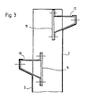
- FIG. 1 shows two elements 1 of a freestanding roof for an industrial building.
- Each element has in section a substantially semicircular shape open upwards, with a width which can be around 2 meters, and can have a length of up to 30 meters.
- the elements are supported at their ends by supports symbolized in A, which can be constituted by the front walls of the building.
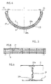
- Each element comprises an exterior wall 2 and an interior wall 3 curved in an identical manner and with the same mechanical strength. Between these walls are arranged, at regular intervals in the longitudinal direction, transverse stiffeners conforming to the shape of the walls (see FIG. 5 for this arrangement) and one of which is shown in section in FIG. 2 and in FIG. 6.
- FIG. 2 There is shown in Figure 2 a variant in which two irons 10, 11 having spread wings form the stiffener 4; they are fixed respectively to the walls 2 and 3, and between the irons 10 and 11 are placed at regular intervals bracing pieces formed by pads 12 of rigid thermally insulating material, for example wood or rigid plastic material.
- the connection between the bars 10 and 11 is ensured by clamping pieces 13, 14 respectively enclosing the pads 12 and connected by blocking a nut 15 on a bolt 16.
- the walls 2 and 3 are, in the embodiment of Figure 1 made of steel tanks, that is to say of ribbed steel sheets. These containers are commercially available and each wall will be formed from one or more of these containers, depending on the required width. If a wall comprises several tanks, the connection will be obtained by covering the waves (or ribs) and fixing by screws.
- longitudinal profiles 17 are provided, housed in the last wave of the outer wall 2, and likewise longitudinal profiles 18 housed in the last wave of the inner wall 3.
- Each of these sections constitute strips which work in compression, since the vault is open upwards.
- Each profile is placed between two consecutive stiffeners 4 and is fixed by its ends on plates 19 welded to the stiffeners 4.
- connecting bars 20 Between two adjacent roofing elements are placed connecting bars 20 forming spacers, which are fixed to the exposed ends of the stiffeners 4. Above the connecting bars 20 is placed a watertight ridge 21, and under the bars 20 is a sub- ceiling 22 supported by the upper face of the longitudinal compression strips 18 opposite. A layer of thermal insulation 23 is placed on the sub-ceiling 22.
- a simple translucent skylight could also be placed between two adjacent roof elements.
- the interior 3 contributes by its resistance to the rigidity of the roof, instead of forming dead as the wall exterior must
- the roof elements 1 are prefabricated in the factory and the only operations remaining to be carried out on the site are the installation of the elements 1 on the support walls and the installation of the connecting bars, the ridge, etc. ., between elements 1.
- Such a variant reinforces the role of transmission of forces between the walls played by the compression profiles.
- the sections 25, 26 are moreover filled with a thermal insulation foam formed in place.
- the stiffeners also have a different structure from what has been described above. They are each formed of two T sections 28a, 28b fixed respectively to the outer wall and to the inner wall, preferably by means of self-tapping screws, not shown. The sections 28a, 28b are separated and joined at intervals by bracing pieces constituted by metal plates 29 welded to the webs of the sections 28a, 28b. Such an embodiment has the advantage of great simplicity of construction and provides a very satisfactory thermal break between walls, over the entire length of the stiffener 27.
Landscapes
- Engineering & Computer Science (AREA)
- Architecture (AREA)
- Physics & Mathematics (AREA)
- Electromagnetism (AREA)
- Civil Engineering (AREA)
- Structural Engineering (AREA)
- Building Environments (AREA)
- Roof Covering Using Slabs Or Stiff Sheets (AREA)
- Paints Or Removers (AREA)
- Body Structure For Vehicles (AREA)
- Vehicle Interior And Exterior Ornaments, Soundproofing, And Insulation (AREA)
Priority Applications (1)
| Application Number | Priority Date | Filing Date | Title |
|---|---|---|---|
| AT80400257T ATE7720T1 (de) | 1979-02-26 | 1980-02-22 | Aus gewoelbefoermigen modul-elementen zusammengesetztes, selbsttragendes dach fuer gebaeude. |
Applications Claiming Priority (2)
| Application Number | Priority Date | Filing Date | Title |
|---|---|---|---|
| FR7904880A FR2449755A1 (fr) | 1979-02-26 | 1979-02-26 | Toiture autoportante pour batiments, composee d'elements modulaires |
| FR7904880 | 1979-02-26 |
Publications (3)
| Publication Number | Publication Date |
|---|---|
| EP0015213A1 EP0015213A1 (fr) | 1980-09-03 |
| EP0015213B1 EP0015213B1 (fr) | 1984-05-30 |
| EP0015213B2 true EP0015213B2 (fr) | 1989-02-15 |
Family
ID=9222460
Family Applications (1)
| Application Number | Title | Priority Date | Filing Date |
|---|---|---|---|
| EP80400257A Expired EP0015213B2 (fr) | 1979-02-26 | 1980-02-22 | Toiture autoportante pour bâtiments, composée d'éléments modulaires en forme de voûte |
Country Status (6)
| Country | Link |
|---|---|
| US (1) | US4395853A (enExample) |
| EP (1) | EP0015213B2 (enExample) |
| JP (1) | JPS6037261B2 (enExample) |
| AT (1) | ATE7720T1 (enExample) |
| DE (1) | DE3067997D1 (enExample) |
| FR (1) | FR2449755A1 (enExample) |
Cited By (1)
| Publication number | Priority date | Publication date | Assignee | Title |
|---|---|---|---|---|
| DE19529035A1 (de) * | 1995-08-08 | 1997-02-13 | Grad Johann | Selbsttragende Dachkonstruktion |
Families Citing this family (7)
| Publication number | Priority date | Publication date | Assignee | Title |
|---|---|---|---|---|
| FR2562925B1 (fr) * | 1984-04-17 | 1987-06-26 | Lelan Jean Claude | Toiture a double paroi profilee |
| FR2581681B1 (fr) * | 1985-05-07 | 1988-05-13 | Acmc Export | Element autoportant pour la realisation d'une toiture de batiment, comprenant une ossature metallique associee a une couverture isolante monobloc, ossature metallique et couverture isolante le composant et toiture en resultant |
| US4671032A (en) * | 1986-03-31 | 1987-06-09 | Philip W. Reynolds | Thermally insulating structural panel with load-bearing skin |
| FR2607538B1 (fr) * | 1986-11-28 | 1989-03-10 | Lelan Jean Claude | Dispositif de remise en etat, ou " rehabilitation ", de toitures realisees en coques |
| NL9400028A (nl) * | 1994-01-07 | 1995-08-01 | Bennenk Hendrik W | Vrijdragende dakconstructie. |
| IT1275242B (it) * | 1995-02-17 | 1997-07-31 | Dlc Srl | Sistema di copertura perfezionato comprendente tegoli alternati a coppelle |
| EP2428625A1 (en) | 2010-09-10 | 2012-03-14 | Profilia S.r.l. | Roof structure |
Family Cites Families (9)
| Publication number | Priority date | Publication date | Assignee | Title |
|---|---|---|---|---|
| US2407252A (en) * | 1943-10-22 | 1946-09-10 | Edwin R Closs | Prefabricated building |
| US2419149A (en) * | 1944-01-01 | 1947-04-15 | Mobile Refrigeration Inc | Electrical method of mechanically connecting and mutually insulating spaced metal elements |
| FR1494733A (fr) * | 1966-03-01 | 1967-09-15 | Aluminium Francais | élément de structure autoportante à grande résistance et application aux toitures autoportantes |
| US3335530A (en) * | 1966-05-31 | 1967-08-15 | Leslie A Hurd | Roofing systems with supporting strap assemblies |
| FR1558925A (enExample) * | 1967-08-09 | 1969-03-07 | ||
| FR2028056A1 (enExample) * | 1969-01-17 | 1970-10-09 | Pierre Claude | |
| FR2116972A6 (enExample) * | 1970-12-08 | 1972-07-21 | Leone Paul | |
| FR2147866B1 (enExample) * | 1971-08-04 | 1974-04-26 | Caen Atel Constr Metal | |
| FR2407313A1 (fr) * | 1977-10-26 | 1979-05-25 | Caen Atel Constr Metal | Procede de construction d'une toiture auto-portante, eclisse pour la mise en oeuvre dudit procede de toiture auto-portante correspondante |
-
1979
- 1979-02-26 FR FR7904880A patent/FR2449755A1/fr active Granted
-
1980
- 1980-02-21 US US06/123,471 patent/US4395853A/en not_active Expired - Lifetime
- 1980-02-22 AT AT80400257T patent/ATE7720T1/de not_active IP Right Cessation
- 1980-02-22 EP EP80400257A patent/EP0015213B2/fr not_active Expired
- 1980-02-22 DE DE8080400257T patent/DE3067997D1/de not_active Expired
- 1980-02-26 JP JP55022333A patent/JPS6037261B2/ja not_active Expired
Cited By (2)
| Publication number | Priority date | Publication date | Assignee | Title |
|---|---|---|---|---|
| DE19529035A1 (de) * | 1995-08-08 | 1997-02-13 | Grad Johann | Selbsttragende Dachkonstruktion |
| DE19529035C2 (de) * | 1995-08-08 | 1999-07-22 | Johann Dipl Ing Grad | Selbsttragende Dachkonstruktion |
Also Published As
| Publication number | Publication date |
|---|---|
| JPS6037261B2 (ja) | 1985-08-24 |
| EP0015213B1 (fr) | 1984-05-30 |
| DE3067997D1 (en) | 1984-07-05 |
| US4395853A (en) | 1983-08-02 |
| FR2449755A1 (fr) | 1980-09-19 |
| JPS55116947A (en) | 1980-09-08 |
| ATE7720T1 (de) | 1984-06-15 |
| EP0015213A1 (fr) | 1980-09-03 |
| FR2449755B1 (enExample) | 1982-07-02 |
Similar Documents
| Publication | Publication Date | Title |
|---|---|---|
| FR2546938A1 (fr) | Structure mixte de plancher | |
| EP0015213B2 (fr) | Toiture autoportante pour bâtiments, composée d'éléments modulaires en forme de voûte | |
| FR2701978A1 (fr) | Paroi intérieure de bardage ou de couverture métallique de bâtiment et profil de renfort pour une telle paroi. | |
| FR2570111A1 (fr) | Bloc de construction en beton a structure sandwich, et element d'armature et plaque d'isolation pour un tel bloc | |
| FR2560621A1 (fr) | Element nervure et dalle composee de tels elements ainsi que le procede de fabrication de ces elements et les moyens en vue de la mise en oeuvre de ce procede | |
| FR2700563A3 (fr) | Elément de caniveau en béton armé. | |
| FR2786796A1 (fr) | Systemes structurels triangules en bois, tels que charpentes , ponts, planchers | |
| EP0080398A1 (fr) | Ossature de bâtiment industriel constituée en éléments préfabriqués de béton armé | |
| FR2486126A1 (fr) | Elements modulaires pour la construction de mur isolant thermique et phonique | |
| FR2516217A1 (fr) | Capteur solaire plan | |
| CH436640A (fr) | Dalle en béton | |
| EP0440567A1 (fr) | Poutres et poteaux, simples et doubles, constitués par la réunion de profilés à section droite en Z, et permettant notamment la réalisation d'un portique ou d'une potence destinée à une construction de bâtiment | |
| EP1022404A1 (fr) | Système de couverture préfabriqée en béton armé et précontraint pour la réalisation de bâtiments | |
| FR2733263A1 (fr) | Panneau composite, assemblage de panneaux et batiment de type prefabrique construit a l'aide de tels panneaux | |
| FR2524523A1 (fr) | Element de construction composite, notamment pour la realisation de batiments, et panneau comportant application de cet element | |
| FR2661702A1 (fr) | Panneau prefabrique beton-isolant, procede pour sa fabrication et mur de batiment forme de tels panneaux. | |
| FR2585048A1 (fr) | Construction prefabriquee | |
| EP0260197A1 (fr) | Pont en béton armé à coffrage intégré | |
| FR2525659A1 (fr) | Element autoportant et de grande longueur pour la realisation d'une toiture de batiment | |
| FR2512869A1 (fr) | Batiment, notamment pour l'elevage | |
| FR2659944A1 (fr) | Revetement calorifuge pour citerne routiere. | |
| BE885595Q (fr) | Panneaux de construction modulaires | |
| BE839639A (fr) | Structure d'elements modulaires de construction prefabriquee | |
| FR2546943A1 (fr) | Perfectionnements aux constructions prefabriquees et a leurs composants | |
| FR2668192A1 (fr) | Plaque de couverture en beton arme precontraint. |
Legal Events
| Date | Code | Title | Description |
|---|---|---|---|
| PUAI | Public reference made under article 153(3) epc to a published international application that has entered the european phase |
Free format text: ORIGINAL CODE: 0009012 |
|
| AK | Designated contracting states |
Designated state(s): AT BE CH DE FR GB IT LU NL SE |
|
| 17P | Request for examination filed |
Effective date: 19801231 |
|
| ITF | It: translation for a ep patent filed | ||
| GRAA | (expected) grant |
Free format text: ORIGINAL CODE: 0009210 |
|
| AK | Designated contracting states |
Designated state(s): AT BE CH DE FR GB IT LU NL SE |
|
| REF | Corresponds to: |
Ref document number: 7720 Country of ref document: AT Date of ref document: 19840615 Kind code of ref document: T |
|
| REF | Corresponds to: |
Ref document number: 3067997 Country of ref document: DE Date of ref document: 19840705 |
|
| PLBI | Opposition filed |
Free format text: ORIGINAL CODE: 0009260 |
|
| PG25 | Lapsed in a contracting state [announced via postgrant information from national office to epo] |
Ref country code: LU Free format text: LAPSE BECAUSE OF NON-PAYMENT OF DUE FEES Effective date: 19850228 |
|
| 26 | Opposition filed |
Opponent name: GRESCHBACH INDUSTRIE GMBH & CO Effective date: 19850205 |
|
| NLR1 | Nl: opposition has been filed with the epo |
Opponent name: GRESCHBACH INDUSTRIE GMBH & CO. |
|
| PGFP | Annual fee paid to national office [announced via postgrant information from national office to epo] |
Ref country code: LU Payment date: 19860404 Year of fee payment: 7 |
|
| PGFP | Annual fee paid to national office [announced via postgrant information from national office to epo] |
Ref country code: NL Payment date: 19870228 Year of fee payment: 8 Ref country code: AT Payment date: 19870228 Year of fee payment: 8 |
|
| PG25 | Lapsed in a contracting state [announced via postgrant information from national office to epo] |
Ref country code: AT Effective date: 19880222 |
|
| PG25 | Lapsed in a contracting state [announced via postgrant information from national office to epo] |
Ref country code: SE Effective date: 19880223 |
|
| PG25 | Lapsed in a contracting state [announced via postgrant information from national office to epo] |
Ref country code: CH Effective date: 19880229 |
|
| PG25 | Lapsed in a contracting state [announced via postgrant information from national office to epo] |
Ref country code: NL Effective date: 19880901 |
|
| NLV4 | Nl: lapsed or anulled due to non-payment of the annual fee | ||
| REG | Reference to a national code |
Ref country code: CH Ref legal event code: PL |
|
| PUAH | Patent maintained in amended form |
Free format text: ORIGINAL CODE: 0009272 |
|
| STAA | Information on the status of an ep patent application or granted ep patent |
Free format text: STATUS: PATENT MAINTAINED AS AMENDED |
|
| 27A | Patent maintained in amended form |
Effective date: 19890215 |
|
| AK | Designated contracting states |
Kind code of ref document: B2 Designated state(s): AT BE CH DE FR GB IT LU NL SE |
|
| ITF | It: translation for a ep patent filed | ||
| ITTA | It: last paid annual fee | ||
| PGFP | Annual fee paid to national office [announced via postgrant information from national office to epo] |
Ref country code: GB Payment date: 19940208 Year of fee payment: 15 |
|
| EUG | Se: european patent has lapsed |
Ref document number: 80400257.4 Effective date: 19880927 |
|
| PG25 | Lapsed in a contracting state [announced via postgrant information from national office to epo] |
Ref country code: GB Effective date: 19950222 |
|
| GBPC | Gb: european patent ceased through non-payment of renewal fee |
Effective date: 19950222 |
|
| PGFP | Annual fee paid to national office [announced via postgrant information from national office to epo] |
Ref country code: DE Payment date: 19990216 Year of fee payment: 20 |
|
| PGFP | Annual fee paid to national office [announced via postgrant information from national office to epo] |
Ref country code: FR Payment date: 19990222 Year of fee payment: 20 |
|
| PGFP | Annual fee paid to national office [announced via postgrant information from national office to epo] |
Ref country code: BE Payment date: 19990323 Year of fee payment: 20 |
|
| BE20 | Be: patent expired |
Free format text: 20000222 *BATIROC |