EP0014632B1 - Improved drum brake assembly - Google Patents
Improved drum brake assembly Download PDFInfo
- Publication number
- EP0014632B1 EP0014632B1 EP80400135A EP80400135A EP0014632B1 EP 0014632 B1 EP0014632 B1 EP 0014632B1 EP 80400135 A EP80400135 A EP 80400135A EP 80400135 A EP80400135 A EP 80400135A EP 0014632 B1 EP0014632 B1 EP 0014632B1
- Authority
- EP
- European Patent Office
- Prior art keywords
- brake
- pawl
- abutment
- brake shoes
- shoe
- Prior art date
- Legal status (The legal status is an assumption and is not a legal conclusion. Google has not performed a legal analysis and makes no representation as to the accuracy of the status listed.)
- Expired
Links
Images
Classifications
-
- F—MECHANICAL ENGINEERING; LIGHTING; HEATING; WEAPONS; BLASTING
- F16—ENGINEERING ELEMENTS AND UNITS; GENERAL MEASURES FOR PRODUCING AND MAINTAINING EFFECTIVE FUNCTIONING OF MACHINES OR INSTALLATIONS; THERMAL INSULATION IN GENERAL
- F16D—COUPLINGS FOR TRANSMITTING ROTATION; CLUTCHES; BRAKES
- F16D65/00—Parts or details
- F16D65/14—Actuating mechanisms for brakes; Means for initiating operation at a predetermined position
- F16D65/16—Actuating mechanisms for brakes; Means for initiating operation at a predetermined position arranged in or on the brake
- F16D65/22—Actuating mechanisms for brakes; Means for initiating operation at a predetermined position arranged in or on the brake adapted for pressing members apart, e.g. for drum brakes
-
- F—MECHANICAL ENGINEERING; LIGHTING; HEATING; WEAPONS; BLASTING
- F16—ENGINEERING ELEMENTS AND UNITS; GENERAL MEASURES FOR PRODUCING AND MAINTAINING EFFECTIVE FUNCTIONING OF MACHINES OR INSTALLATIONS; THERMAL INSULATION IN GENERAL
- F16D—COUPLINGS FOR TRANSMITTING ROTATION; CLUTCHES; BRAKES
- F16D65/00—Parts or details
- F16D65/38—Slack adjusters
- F16D65/40—Slack adjusters mechanical
- F16D65/52—Slack adjusters mechanical self-acting in one direction for adjusting excessive play
- F16D65/56—Slack adjusters mechanical self-acting in one direction for adjusting excessive play with screw-thread and nut
- F16D65/561—Slack adjusters mechanical self-acting in one direction for adjusting excessive play with screw-thread and nut for mounting within the confines of a drum brake
- F16D65/563—Slack adjusters mechanical self-acting in one direction for adjusting excessive play with screw-thread and nut for mounting within the confines of a drum brake arranged adjacent to service brake actuator, e.g. on parking brake lever, and not subjected to service brake force
Definitions
- the present invention relates to an improved drum brake assembly having an automatic adjuster which compensates for lining wear on a pair of brake shoes.
- a drum brake assembly pivoted an adjusting pawl on one brake shoe and engaged the pawl with a ratchet wheel of an extendible member to provide for adjustment of the extendible member when the running clearance between a pair of brake shoes and a rotatable member was excessive.
- a parking lever was pivotally mounted to the one brake shoe or the other brake shoe and engaged with the extendible member so as to move the pair of brake shoes from a non-braking position to a braking position when the parking lever was rotated or moved by a vehicle operator.
- a hydraulic actuator was operable to move the pair of brake shoes to the braking position.
- the hydraulic actuator included a pair of pistons which carried hardened stops or plugs to engage the pair of brake shoes, so as to protect the pistons at the point of contact with the pair of brake shoes.
- the adjusting pawl is pivotally mounted on one of the pair of brakes shoes via a mounting pin secured to the one brake shoe. During or prior to assembly of the drum brake assembly, it is necessary to secure the mounting pin to the one brake shoe.
- An improved drum brake having a hydraulic actuator cooperating with a pair of brake shoes to urge the latter to a position in engagement with a rotatable drum during braking, an adjustment mechanism of the type including an extendible member engaging the pair of brake shoes to define a non-braking position for the brake shoes, a resilient member cooperating with said brake shoes to urge them toward their non-braking position, a pawl pivotally mounted relative to said extendible member and engageable therewith to provide extension of said member in the event of excessive movement of said brake shoes between their non-braking and engagement positions said pawl including one arm engaging said extendible member and another arm, characterised in that said other arm defines an arcuate abutment and a pocket, said abutment in part defining said pocket, said actuator having an arcuate recess pivotally receiving said abutment, one of said brake shoes terminating in an end of acruate shape, said arcuate brake shoe end being pivotally received in said pocket whereby said pawl is pivotally held between said one brake shoe and said actuator and may be pi
- the drum brake assembly of Figure 1 is generally referred to as a non-servo drum brake having a backing plate 10 which includes an anchor 12 to receive torque developed by a pair of brake shoes 14 and 16.
- the backing plate also carried a hydraulic actuator 18 which receives pressurized fluid during a brake application to expand the pair of brake shoes from a non-braking position to a braking position.
- the non-braking position is substantially defined by an extendible member 20 which is engageable with the pair of brake shoes to limit retraction of the latter subsequent to a brake application.
- a pawl 22 includes a first arm 24 which is engageable with a ratchet wheel 26 on the extendible member 20.
- a resilient member 28 extends from the one brake shoe 14 to the pawl 22.
- the pawl is pivoted counterclockwise so as to index above a successive tooth on the ratchet wheel 26.
- the resilient members 28 and 29 retract the pair of brake shoes to the non-braking position.
- the pawl pivots in a clockwise direction thereby rotating the ratchet wheel and extending the extendible member 20:
- the pawl 22 includes a second arm 30 biased by resilient member 28 into engagement with the extendible member 20 and a third arm 32 of the pawl substantially defines an arcuate abutment 34 engaging the wheel cylinder 18.
- the abutment 34 pivotally engages a piston 36 of the hydraulic actuator 18 and the piston 36 includes an arcuate recess for receiving the abutment 34.
- the brake shoe 16 terminates in an end 38, which opposes the abutment 34 opposite the piston 36. Viewing Figures 2 and 3, the abutment 34 forms a picket 40 to pivotally receive the end 38 of the brake shoe 16.
- a tab 42 extends from the pawl 22 and is inserted in a slot 44 on the brake shoe 16. The tab 42 provides for retraction of the brake shoe 16 by the resilient member 28 when hydraulic pressure is released from the hydraulic actuator 18.
- a parking lever 48 forms an arcuate abutment 50 at one end in engagement with a piston 52 of the hydraulic actuator 18.
- the abutment 50 forms a pocket 54 for pivotally receiving an end 56 of the brake shoe 14, substantially as shown in Figure 4, and the abutment 50 is pivotally received within a recess on the piston 52.
- the pistons 36 and 52 When a brake application is initiated, the pistons 36 and 52 are urged outwardly from the hydraulic actuator 18. The pistons 36 and 52 bias the abutment 34 on the pawl and the abutment 50 on the parking lever to move away from the hydraulic actuator 18. As a result the abutment 34 pivots and slides relative to the piston 36.
- the resilient member 28 bias the pawl arm 30 and extendible member 20 to move to the right with the brake shoe 14 while the piston 36 biases the pawl arm 32 to move to the left so that the arm 24 is movable relative tp the ratchet wheel 26.
- the arm 24 will position itself over a successive tooth on the ratchet wheel so that upon retraction of the pair of brake shoes, the arm 24 will engage the successive tooth and cause the ratchet wheel to rotate thereby extending the length of the extendible member.
- the increased length of the extendible member cooperates with the pair of brake shoes to adjust the non-braking position closer to the braking position.
- the arcuate abutments 34 and 50 separate the brake shoes from the hydraulic actuator while transmitting movement from the hydraulic actuator to the brake shoes.
- the arcuate abutments form pivotal connections with each respective brake shoe in the absence of connecting pins or the like.
- the abutment 34 on the pawl is directly engageable with the piston 36 so that the pawl begins to rotate as soon as the piston 36 of the hydraulic actuator moves.
- the abutment 50 is retained between the piston 52 and the brake shoe end 56 via the resilient members 28 and 29 which bias the brake shoe 14 and the abutment 50 toward the hydraulic actuator 18.
Landscapes
- Engineering & Computer Science (AREA)
- General Engineering & Computer Science (AREA)
- Mechanical Engineering (AREA)
- Braking Arrangements (AREA)
Description
- The present invention relates to an improved drum brake assembly having an automatic adjuster which compensates for lining wear on a pair of brake shoes.
- Heretofore, a drum brake assembly pivoted an adjusting pawl on one brake shoe and engaged the pawl with a ratchet wheel of an extendible member to provide for adjustment of the extendible member when the running clearance between a pair of brake shoes and a rotatable member was excessive. In addition, a parking lever was pivotally mounted to the one brake shoe or the other brake shoe and engaged with the extendible member so as to move the pair of brake shoes from a non-braking position to a braking position when the parking lever was rotated or moved by a vehicle operator.
- Moreover, a hydraulic actuator was operable to move the pair of brake shoes to the braking position. The hydraulic actuator included a pair of pistons which carried hardened stops or plugs to engage the pair of brake shoes, so as to protect the pistons at the point of contact with the pair of brake shoes.
- In the United States Patent 4,101,011, the adjusting pawl is pivotally mounted on one of the pair of brakes shoes via a mounting pin secured to the one brake shoe. During or prior to assembly of the drum brake assembly, it is necessary to secure the mounting pin to the one brake shoe.
- It is an object of the present invention to provide a drum brake assembly of the above referenced type wherein the pivotal mounting of the adjusting pawl is provided in the absence of a mounting or connecting pin.
- An improved drum brake having a hydraulic actuator cooperating with a pair of brake shoes to urge the latter to a position in engagement with a rotatable drum during braking, an adjustment mechanism of the type including an extendible member engaging the pair of brake shoes to define a non-braking position for the brake shoes, a resilient member cooperating with said brake shoes to urge them toward their non-braking position, a pawl pivotally mounted relative to said extendible member and engageable therewith to provide extension of said member in the event of excessive movement of said brake shoes between their non-braking and engagement positions said pawl including one arm engaging said extendible member and another arm, characterised in that said other arm defines an arcuate abutment and a pocket, said abutment in part defining said pocket, said actuator having an arcuate recess pivotally receiving said abutment, one of said brake shoes terminating in an end of acruate shape, said arcuate brake shoe end being pivotally received in said pocket whereby said pawl is pivotally held between said one brake shoe and said actuator and may be pivoted upon brake actuation to provide for extension of said extendible member.
- It is an advantage of the present invention that a pivotal mounting is provided for an adjusting pawl in the absence of a mounting or connecting pin, thereby reducing the number of parts and simplifying assembly for the drum brake.
- The invention will now be described with reference to the accompanying drawings wherein:
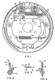
- Figure 1 is a front view of a drum brake assembly;
- Figure 2 is a cross-sectional view taken along line 2-2 of Figure 1;
- Figure 3 is a cross-sectional view taken along line 3-3 of Figure 1; and
- Figure 4 is a cross-sectional view taken along line 4-4 of Figure 1.
- The drum brake assembly of Figure 1 is generally referred to as a non-servo drum brake having a
backing plate 10 which includes ananchor 12 to receive torque developed by a pair ofbrake shoes hydraulic actuator 18 which receives pressurized fluid during a brake application to expand the pair of brake shoes from a non-braking position to a braking position. The non-braking position is substantially defined by anextendible member 20 which is engageable with the pair of brake shoes to limit retraction of the latter subsequent to a brake application. In order to extend theextendible member 20, apawl 22 includes afirst arm 24 which is engageable with aratchet wheel 26 on theextendible member 20. Aresilient member 28 extends from the onebrake shoe 14 to thepawl 22. If the brake shoes wear and if the movement of the brake shoes from a non-braking position to a braking position is above a predetermined value, the pawl is pivoted counterclockwise so as to index above a successive tooth on theratchet wheel 26. Upon termination of braking, theresilient members - The
pawl 22 includes asecond arm 30 biased byresilient member 28 into engagement with theextendible member 20 and athird arm 32 of the pawl substantially defines anarcuate abutment 34 engaging thewheel cylinder 18. In particular, theabutment 34 pivotally engages apiston 36 of thehydraulic actuator 18 and thepiston 36 includes an arcuate recess for receiving theabutment 34. Thebrake shoe 16 terminates in anend 38, which opposes theabutment 34 opposite thepiston 36. Viewing Figures 2 and 3, theabutment 34 forms apicket 40 to pivotally receive theend 38 of thebrake shoe 16. Atab 42 extends from thepawl 22 and is inserted in aslot 44 on thebrake shoe 16. Thetab 42 provides for retraction of thebrake shoe 16 by theresilient member 28 when hydraulic pressure is released from thehydraulic actuator 18. - A
parking lever 48 forms an arcuate abutment 50 at one end in engagement with apiston 52 of thehydraulic actuator 18. The abutment 50 forms apocket 54 for pivotally receiving anend 56 of thebrake shoe 14, substantially as shown in Figure 4, and the abutment 50 is pivotally received within a recess on thepiston 52. - When a brake application is initiated, the
pistons hydraulic actuator 18. Thepistons abutment 34 on the pawl and the abutment 50 on the parking lever to move away from thehydraulic actuator 18. As a result theabutment 34 pivots and slides relative to thepiston 36. Theresilient member 28 bias thepawl arm 30 andextendible member 20 to move to the right with thebrake shoe 14 while thepiston 36 biases thepawl arm 32 to move to the left so that thearm 24 is movable relative tp theratchet wheel 26. If the pair of brake shoes move through an excessive distance from the non-braking position to the braking position, thearm 24 will position itself over a successive tooth on the ratchet wheel so that upon retraction of the pair of brake shoes, thearm 24 will engage the successive tooth and cause the ratchet wheel to rotate thereby extending the length of the extendible member. The increased length of the extendible member cooperates with the pair of brake shoes to adjust the non-braking position closer to the braking position. When theparking lever 48 is actuated to rotate in a clockwise direction, viewing Figure 1, the abutment 50 pivots and slides relative to thepiston 52. Moreover, theextendible member 20 is moved to the left to bias thebrake shoe 16 away fromhydraulic actuator 18, while thepocket 54 on the rotatingparking lever 48 biases thebrake shoe 14 away from the hydraulic actuator. - From the foregoing description it is seen that the
arcuate abutments 34 and 50 separate the brake shoes from the hydraulic actuator while transmitting movement from the hydraulic actuator to the brake shoes. The arcuate abutments form pivotal connections with each respective brake shoe in the absence of connecting pins or the like. Theabutment 34 on the pawl is directly engageable with thepiston 36 so that the pawl begins to rotate as soon as thepiston 36 of the hydraulic actuator moves. Moreover, the abutment 50 is retained between thepiston 52 and thebrake shoe end 56 via theresilient members brake shoe 14 and the abutment 50 toward thehydraulic actuator 18.
Claims (3)
Applications Claiming Priority (2)
| Application Number | Priority Date | Filing Date | Title |
|---|---|---|---|
| US8729 | 1979-02-02 | ||
| US06/008,729 US4222467A (en) | 1979-02-02 | 1979-02-02 | Drum brake adjuster |
Publications (2)
| Publication Number | Publication Date |
|---|---|
| EP0014632A1 EP0014632A1 (en) | 1980-08-20 |
| EP0014632B1 true EP0014632B1 (en) | 1983-01-26 |
Family
ID=21733322
Family Applications (1)
| Application Number | Title | Priority Date | Filing Date |
|---|---|---|---|
| EP80400135A Expired EP0014632B1 (en) | 1979-02-02 | 1980-01-28 | Improved drum brake assembly |
Country Status (7)
| Country | Link |
|---|---|
| US (1) | US4222467A (en) |
| EP (1) | EP0014632B1 (en) |
| JP (1) | JPS55103128A (en) |
| AR (1) | AR218415A1 (en) |
| AU (1) | AU5482280A (en) |
| CA (1) | CA1141681A (en) |
| DE (1) | DE3061703D1 (en) |
Cited By (1)
| Publication number | Priority date | Publication date | Assignee | Title |
|---|---|---|---|---|
| DE3218788A1 (en) * | 1981-06-03 | 1982-12-30 | Lucas Ind Plc | SELF-ADJUSTING DEVICE FOR A BRAKE |
Families Citing this family (7)
| Publication number | Priority date | Publication date | Assignee | Title |
|---|---|---|---|---|
| US4442923A (en) * | 1980-07-18 | 1984-04-17 | Honda Giken Kogyo Kabushiki Kaisha | Automatic regulator for internally expanding drum brake |
| US4653615A (en) * | 1980-10-02 | 1987-03-31 | Automotive Products Limited | Automatic wear adjuster for drum brakes |
| US4353438A (en) * | 1980-10-02 | 1982-10-12 | The Bendix Corporation | Actuator assembly for a drum brake having an extendible assembly |
| FR2503302B1 (en) * | 1981-03-31 | 1986-02-28 | Dba | SELF-ADJUSTING DRUM BRAKE |
| GB2185297A (en) * | 1986-01-09 | 1987-07-15 | Automotive Products Plc | Internal shoe drum brake |
| FR2623864B1 (en) * | 1987-12-01 | 1990-03-16 | Bendix France | SELF-ADJUSTING DRUM BRAKE |
| US5538112A (en) * | 1994-10-11 | 1996-07-23 | Kelsey-Hayes Company | Parking and emergancy brake actuating lever for drum brake assembly |
Citations (1)
| Publication number | Priority date | Publication date | Assignee | Title |
|---|---|---|---|---|
| US4101011A (en) * | 1977-04-28 | 1978-07-18 | The Bendix Corporation | Drum brake adjuster |
Family Cites Families (8)
| Publication number | Priority date | Publication date | Assignee | Title |
|---|---|---|---|---|
| US2389618A (en) * | 1942-08-01 | 1945-11-27 | Bendix Aviat Corp | Brake |
| US2378662A (en) * | 1944-03-20 | 1945-06-19 | Shuman Moses | Hydraulic brake |
| US3360084A (en) * | 1966-07-14 | 1967-12-26 | Kelsey Hayes Co | Automatic brake adjuster |
| GB1341549A (en) * | 1967-03-21 | 1973-12-25 | ||
| US3706360A (en) * | 1969-12-25 | 1972-12-19 | Aisin Seiki | Automatic brake adjuster |
| US3708044A (en) * | 1971-05-18 | 1973-01-02 | Aisin Seiki | Vehicle expanding brake assembly |
| DE2156899C2 (en) * | 1971-11-16 | 1982-09-23 | Alfred Teves Metallwarenfabrik Gmbh & Co Ohg, 5275 Bergneustadt | Automatic adjustment device for a drum brake |
| GB1402527A (en) * | 1971-11-23 | 1975-08-13 | Girling Ltd | Automatic adjuster for an internal shoe drum brake |
-
1979
- 1979-02-02 US US06/008,729 patent/US4222467A/en not_active Expired - Lifetime
-
1980
- 1980-01-02 CA CA000342865A patent/CA1141681A/en not_active Expired
- 1980-01-22 AU AU54822/80A patent/AU5482280A/en not_active Abandoned
- 1980-01-28 EP EP80400135A patent/EP0014632B1/en not_active Expired
- 1980-01-28 DE DE8080400135T patent/DE3061703D1/en not_active Expired
- 1980-02-01 JP JP1137280A patent/JPS55103128A/en active Pending
- 1980-02-01 AR AR279833A patent/AR218415A1/en active
Patent Citations (1)
| Publication number | Priority date | Publication date | Assignee | Title |
|---|---|---|---|---|
| US4101011A (en) * | 1977-04-28 | 1978-07-18 | The Bendix Corporation | Drum brake adjuster |
Cited By (1)
| Publication number | Priority date | Publication date | Assignee | Title |
|---|---|---|---|---|
| DE3218788A1 (en) * | 1981-06-03 | 1982-12-30 | Lucas Ind Plc | SELF-ADJUSTING DEVICE FOR A BRAKE |
Also Published As
| Publication number | Publication date |
|---|---|
| EP0014632A1 (en) | 1980-08-20 |
| US4222467A (en) | 1980-09-16 |
| AU5482280A (en) | 1980-08-07 |
| JPS55103128A (en) | 1980-08-07 |
| AR218415A1 (en) | 1980-05-30 |
| DE3061703D1 (en) | 1983-03-03 |
| CA1141681A (en) | 1983-02-22 |
Similar Documents
| Publication | Publication Date | Title |
|---|---|---|
| US3811537A (en) | Shoe drum brakes | |
| US3339678A (en) | Automatic adjuster for non-servo brake | |
| US3709334A (en) | Wheel brake assembly fitted with automatic brake cap adjusting means | |
| GB1493831A (en) | Brakes | |
| US3938407A (en) | Variable ratio parking brake control | |
| US4222467A (en) | Drum brake adjuster | |
| EP0104102B1 (en) | Adjuster assembly for a nonservo drum brake | |
| GB1589123A (en) | Drum brake adjuster | |
| US3400787A (en) | Duo-servo parking brake combined with non-servo service brake | |
| US4588052A (en) | Drum brake | |
| US4394892A (en) | Automated braking-gap adjuster system for mechanical drum brake | |
| US3581847A (en) | Automatic adjusting devices for shoe drum brakes | |
| JPS6119853B2 (en) | ||
| EP0014638B1 (en) | Drum brake adjuster | |
| US3490562A (en) | Spot type disc brakes and adjusting means therefor | |
| US4470486A (en) | Automatic wear adjuster for drum brakes | |
| US3893548A (en) | Application adjuster for drum brake | |
| JPH0221456B2 (en) | ||
| GB1427521A (en) | Shoe drum brakes for vehicles | |
| US4353439A (en) | Drum brake with combined adjuster and wheel cylinder | |
| US2994411A (en) | Automatic brake adjusting devices | |
| US3556262A (en) | Applicator adjuster | |
| US4446949A (en) | Connecting rod and piston device for a brake slack adjuster | |
| US4353438A (en) | Actuator assembly for a drum brake having an extendible assembly | |
| GB1598921A (en) | Internal shoe drum brakes |
Legal Events
| Date | Code | Title | Description |
|---|---|---|---|
| PUAI | Public reference made under article 153(3) epc to a published international application that has entered the european phase |
Free format text: ORIGINAL CODE: 0009012 |
|
| AK | Designated contracting states |
Designated state(s): DE FR GB IT |
|
| 17P | Request for examination filed |
Effective date: 19801118 |
|
| ITF | It: translation for a ep patent filed | ||
| GRAA | (expected) grant |
Free format text: ORIGINAL CODE: 0009210 |
|
| AK | Designated contracting states |
Designated state(s): DE FR GB IT |
|
| PG25 | Lapsed in a contracting state [announced via postgrant information from national office to epo] |
Ref country code: FR Free format text: THE PATENT HAS BEEN ANNULLED BY A DECISION OF A NATIONAL AUTHORITY Effective date: 19830126 |
|
| REF | Corresponds to: |
Ref document number: 3061703 Country of ref document: DE Date of ref document: 19830303 |
|
| PG25 | Lapsed in a contracting state [announced via postgrant information from national office to epo] |
Ref country code: DE Effective date: 19831001 |
|
| EN | Fr: translation not filed | ||
| GBPC | Gb: european patent ceased through non-payment of renewal fee | ||
| PG25 | Lapsed in a contracting state [announced via postgrant information from national office to epo] |
Ref country code: GB Effective date: 19881118 |
|
| PLBE | No opposition filed within time limit |
Free format text: ORIGINAL CODE: 0009261 |
|
| STAA | Information on the status of an ep patent application or granted ep patent |
Free format text: STATUS: NO OPPOSITION FILED WITHIN TIME LIMIT |