EP0014586B1 - Lift truck with light assembly for positioning load-handling device - Google Patents
Lift truck with light assembly for positioning load-handling device Download PDFInfo
- Publication number
- EP0014586B1 EP0014586B1 EP80300338A EP80300338A EP0014586B1 EP 0014586 B1 EP0014586 B1 EP 0014586B1 EP 80300338 A EP80300338 A EP 80300338A EP 80300338 A EP80300338 A EP 80300338A EP 0014586 B1 EP0014586 B1 EP 0014586B1
- Authority
- EP
- European Patent Office
- Prior art keywords
- load
- light source
- handling device
- light
- lift truck
- Prior art date
- Legal status (The legal status is an assumption and is not a legal conclusion. Google has not performed a legal analysis and makes no representation as to the accuracy of the status listed.)
- Expired
Links
- 238000005286 illumination Methods 0.000 claims description 11
- 230000001419 dependent effect Effects 0.000 claims 2
- 230000006378 damage Effects 0.000 description 7
- 230000014509 gene expression Effects 0.000 description 2
- 230000005484 gravity Effects 0.000 description 2
- 238000000429 assembly Methods 0.000 description 1
- 230000000712 assembly Effects 0.000 description 1
- 230000007812 deficiency Effects 0.000 description 1
- 238000000151 deposition Methods 0.000 description 1
- 230000003028 elevating effect Effects 0.000 description 1
- 230000009528 severe injury Effects 0.000 description 1
- 125000006850 spacer group Chemical group 0.000 description 1
Images


Classifications
-
- B—PERFORMING OPERATIONS; TRANSPORTING
- B66—HOISTING; LIFTING; HAULING
- B66F—HOISTING, LIFTING, HAULING OR PUSHING, NOT OTHERWISE PROVIDED FOR, e.g. DEVICES WHICH APPLY A LIFTING OR PUSHING FORCE DIRECTLY TO THE SURFACE OF A LOAD
- B66F9/00—Devices for lifting or lowering bulky or heavy goods for loading or unloading purposes
- B66F9/06—Devices for lifting or lowering bulky or heavy goods for loading or unloading purposes movable, with their loads, on wheels or the like, e.g. fork-lift trucks
- B66F9/075—Constructional features or details
- B66F9/0755—Position control; Position detectors
Definitions
- the invention relates to mobile lift trucks of the kind having a lifting apparatus for raising and lowering a load, a load-handling device which is mounted upon the lifting apparatus and which has a load-engaging member extending generally forwardly from the lifting apparatus towards a forward end of said member, and having also a light for providing illumination.
- lights have been mounted either atop a lift truck overhead guard or upon a lift truck load carriage to provide general illumination to aid a lift truck operator during travelling and during the manipulation of loads in dimly lit areas.
- lights on the overhead guard provide sufficient illumination for lower positions of the load carriage they are normally blocked by the load at intermediate elevations of the carriage and are ineffective when the carriage is in a high-lift position where the operator must be able to determine the relative elevation between the position of the load-engaging member or load forks and the pallet cavities or other spaces into which the forks must be inserted.
- German Patent Specification No. 2254012 shows a lift truck having a light source arranged on a load handling device such that the light source does not have to direct light from considerably above the forks. However, in this case the light is focused so that a fan-shaped light plane is projected which is perceptible as a light line on a selected nearby wall.
- An object of the present invention as claimed is to provide a lift truck with a light assembly which alleviates at least some of the foregoing deficiencies of prior art light assemblies in respect of providing illumination aiding a lift truck operator in positioning the load-handling device with respect to a load to be picked up and or with respect to the place where a load is to be deposited.
- a mobile lift truck having a lifting apparatus for raising and lowering a load, a load-handling device which is mounted upon said lifting apparatus and which has a load-engaging member extending generally forwardly from said lifting apparatus towards a forward end of said member, and having also a light for providing illumination, said light being provided by a light assembly including a light source which is mounted upon said load-handling device at a mounted position rearwardly of the forward end of said load-engaging member and adjacent to the bottom of said load-handling device, characterised in that said light source in said mounted position is arranged to project light forwardly in a generally conical pattern along said load-engaging member such that said light is partially intercepted by said forward end of said load-engaging member thereby forwardly projecting a shadow of said load-engaging member.
- the light source is movably mounted on the load-handling device so that as the load-handling device is lowered, in use, below a predetermined elevation the light source is restrained from further downward movement with the load-handling device.
- This may be done by providing mounting means mounting the light source to the remainder of the truck, the mounting means being adapted to detach said light source from said load-handling device in response to downward movement of said load-handling device below a predetermined elevation and to retain said light source at a detached position during further downward movement of said load-handling device.
- said mounting means may comprise first mutually co-operative members on said light assembly and on said mast respectively for detaching said light source from said load-handling device and for retaining said light source supportably to said mast in said detached position in response to downward movement of said load-handling device below said predetermined elevation.
- the mounting means is also adapted to transfer said light source from said detached position to said mounted position in response to upward movement of said load-handling device above said predetermined elevation and additionally where first mutually co-operative members are provided as aforesaid
- the mounting means also, preferably, includes second mutually cooperative members on said load-handling device and on said light assembly respectively for transferring said light source from said detached position on the mast and attaching said light source supportably to said load-handling device in said mounted position in response to upward movement of said load-handling device above the predetermined elevation.
- the first mutually co-operative members may provide for the light source to be in different attitudes in said detached and mounted positions respectively, and the light source may advantageously be arranged to project light in a more downwardly forward direction when in said detached position, to shine down in front of the truck aiding the operator with respect to manipulation of loads in the lower positions of the load-handling device, particularly in dimly lit areas.
- load engaging members in the form of load forks since this is the most common application, the present invention may also be applicable to other types of load-engaging members such as clamp arms.
- the light assembly includes a light source which is mounted upon the load-handling device, usually the load carriage, at a position so as to project light forwardly in a direction in which a portion of the light is intercepted by the fork, thereby forwardly projecting a shadow of the fork.
- This position of the light source is rearwardly of the forward end of the load fork or other load-engaging member and adjacent to the bottom of the load-handling device, that is, at the same, or approximately the same, elevation as the load fork.
- This unusually low placement of the light source has the important advantages of (a) making the shadow which is cast against the load stack accurately representative of the vertical elevation of the fork, which enables the operator to determine its relative elevation with respect to the stack when operating at substantial height, and (b) placing the light source generally where it will be permitted to project light forwardly despite the presence of the load, projecting the light below the level of the load and through the fork space in a supporting pallet if one is used. In cases where a load is present atop the forks, the light casts a shadow of the forward bottom edge of the load which is also accurately representative of the vertical elevation of the forks.
- the unusually low position of the light source of the load-handling device may require that a portion thereof depend below the bottoms of the forks which, as stated in the preceding section, would normally present a danger of severe damage to the light source when the forks are lowered.
- a further feature in preferred embodiments of the present invention not only prevents such damage, but also enables the light assembly to perform a second useful function when the forks are in a lowered position below the operator's line of sight where vertical elevation of the forks is relatively easy to determine and where, in any case, a load would block the operator's view of the area illuminated by a low-position light.
- a mechanism or mounting arrangement is provided so that the light source is movably mounted on the carriage so as to permit downward movement of the carriage with respect to the light source when the carriage is lowered below a predetermined elevation with respect to a lift truck mast.
- The, a structure on the mast engages the light assembly, lifting it off its detachable mount on the carriage and transferring it to the mast so that it does not travel with the carriage downwardly.
- the light remains at an elevated position on the mast where it is free from damage and, moreover, can be arranged to assume an attitude tilted downwardly with respect to its attitude when mounted on the carriage so as to shine down in front of the truck and provide travelling illumination and aid the operator with respect to the manipulation of loads in the lower carriage positions, particularly in dimly lit areas.
- a reverse transfer takes place whereby the light assembly is retransferred from the mast to the carriage and thus travels with the carriage upwardly in its aforementioned position adjacent the bottom of the carriage.
- the present invention advantageous in providing a lift truck with a light assembly arranged to forwardly project a shadow of a load-engaging member of the lift truck load-handling device, which shadow is substantially accurately indicative of the vertical elevation of the load-engaging member thereby to aid the operator in accurately positioning the load-handling device vertically especially when it is elevated above the operator, but in preferred embodiments it also provides means to alleviate damage to the light assembly when the load-handling device is fully or nearly fully lowered despite a relatively low mounting position of the light assembly on the load-handling device in normal use and may include means for enabling the light assembly to fulfill a different function when the load-handling device is below a predetermined elevation, i.e. providing forwardly and downwardly directed illumination to aid the visibility of the lift truck operator in dimly lit areas for travelling and for the manipulation of the load-handling device in a lowered position.
- the lift truck designated generally as 10 is partially shown comprising a main frame 12 mounted upon traction wheels such as 14 and having a vertically-extending load-lifting mast with an outer section 16 pivotally attached at the bottom thereof to the frame 12 so as to be capable of tilting forwardly and rearwardly in response to the extension or retraction of a hydraulic tilt cylinder, the rod portion of which is shown as 18.
- a hydraulic tilt cylinder the rod portion of which is shown as 18.
- Normally one or more vertically- extensible inner mast sections such as 17 ( Figures 2 and 3) are mounted telescopically within the outer section 16.
- a load-handling device designated generally as 20 which, in the embodiment shown, comprises a load carriage 22 with rollers 24 for permitting vertical movement with respect to the inner section 17, and transversely spaced, forwardly-extending load-engaging members comprising load forks such as 26 mounted thereon (only one of which is shown).
- load fork 26 has an upwardly-facing load-engaging surface 26a, a bottom surface 26b, and a forward end or tip 26c ( Figure 2).
- the light assembly provided is designated generally as 28 and comprises a housing 30 in which is mounted a light source 32 which is preferably a reflector bulb capable of projecting light forwardly in a generally conical pattern.
- the light bulb 32 is energized through an electrical line 34 which can be extended from or retracted into a spring-biased retracting reel 36 rotatably mounted within the housing 30.
- the line 34 is electrically coupled through a revolving connector 38 and electrical lines 40, 42 and 44 ( Figure 4) to the bulb 32.
- a variable resistor 46 is interjected between lines 40 and 42 to compensate for different electrical voltages of the lift truck 10, which vary depending upon the particular battery equipment (not shown) utilized in the truck from which the conduit 34 draws its power. It will be appreciated that the provision of the reel 36 permits a wide range of vertical travel of the light assembly 28 for purposes to be described hereafter.
- the primary purpose of the light assembly is to aid the operator in the manipulation of the load-handling device (e.g. the carriage 22 and forks 26) at positions thereof which are elevated above the operator. This is accomplished by mounting the light assembly 28 upon the load-handling device, as shown in solid lines in Figure 2, and in particular on the carriage 22, such that the light source 32 is adjacent to the bottom of the load-handling device and rearwardly of the forward end 26c of the load-engaging member such as 26.
- the load-engaging member is a fork such as 26 having an upwardly-facing load-engaging surface 26a
- the light source should be at a level below that of the upwardly-facing surface 26a so as not to be blocked by any load thereon.
- the light source 32 is at the same level as, or slightly below, the bottom 26b of the load-engaging member and is positioned in a vertical plane which intersects the load-engaging member longitudinally such that the light source is either directly beneath, or preferably directly behind, the load-engaging member. In this position, with the light source projecting light in a generally conical pattern and in a generally forward direction, a portion of the light will be intercepted by the load-engaging member 26 so as to project a shadow of the load-engaging member forwardly against a load stack, which shadow is accurately indicative of the vertical elevation of the load-engaging member 26.
- the light assembly 28 is positioned transversely outwardly of the outer mast section 16.
- a portion of the light assembly extends downward to or below the bottom of the load-engaging member 26 as depicted in Figure 2.
- the mounting structure by which the light assembly 28 is mounted on the carriage 22 permits movement of the light assembly 28 with respect to the carriage from the above-described operative low mounting position.
- a horizontally-oriented crossbar 48 is provided at the upper forward corner of the light assembly 28 extending between a pair of transversely-spaced flanges 50.
- the crossbar 48 rests by force of gravity upon a transversely- oriented shoulder 52 of a carriage-mounted upwardly and rearwardly slanting support member 54 which fits loosely between the flanges 50.
- the light assembly 28 may be lifted freely from the shoulder 52 and/or pivoted upwardly and rearwardly about the axis of the crossbar 48 (forward pivoting of the light assembly from the position shown in Figure 2 is prevented by the abutment of the flanges 50 against the rearwardly-facing surfaces of the carriage 22).
- an additional mounting feature be utilized to further reduce the chance of damage to the light assembly and, at the same time, provide an additional function for the light assembly.
- This additional mounting feature involves a structure by which the light assembly 28 may be detached automatically from the load carriage 22 and attached to the outer mast section 16 in response to downward movement of the carriage 22 below a predetermined position or elevation.
- a crossbar 56 similar to crossbar 48, is provided at the rear upper corner of the housing 30 between transversely-spaced flanges 58.
- An upwardly-opening support yoke 60 aligned behind the carriage support member 54 as shown in Figure 3, is connected to the outer mast section 16 by a bracket 62 and fits loosely between the flanges 58 so that, upon downward movement of the carriage 22, the crossbar 56 becomes engaged with the yoke 60 when the carriage is at a predetermined elevation approximately level with the operator's horizontal line of sight.
- the yoke 60 prevents further downward movement of the light assembly 28, and accordingly the forward crossbar 48 disengages from the carriage-mounted support member 54.
- the light assembly 28 is nowhere near ground level where it can be damaged by contact with the floor or other obstacles. Rather the light assembly remains at a higher level attached to the outer section 16 of the mast as shown in Figure 1.
- the detachment of the light assembly 28 from the carriage 22 permits the light assembly to hang freely from the crossbar 56. Since the center of gravity of the light assembly 28 is horizontally forward of the crossbar 56 when the light assembly is vertical, the light assembly automatically assumes a downwardly-tilted position as shown in Figure 1 so as to direct light more downwardly than when the light assembly was attached to the carriage 22. This enables the light to perform the additional function of illuminating the area in front of the lift truck when the carriage is lowered, to aid the operator in the manipulation of loads and provide travelling illumination for operation in dimly lit areas.
- the elevated position of the light assembly 28 when the carriage is lowered provides excellent illumination for these purposes even when a load is being carried upon the forks 26, since the light source 32 will normally be above the load thereby preventing any blockage of the light.
- the support member 54 Upon movement of the carriage in an up ward direction, the support member 54 once more engages the forward crossbar 48 when the carriage reaches a predetermined elevation and lifts the light assembly 28 from the yoke 60. Upon further elevation of the carriage, the light assembly 28 assumes its low (relative to the carriage), untilted position as shown in Figure 2 for performance of its fork level indicating functions at higher carriage elevations.
Landscapes
- Engineering & Computer Science (AREA)
- Transportation (AREA)
- Structural Engineering (AREA)
- Civil Engineering (AREA)
- Life Sciences & Earth Sciences (AREA)
- Geology (AREA)
- Mechanical Engineering (AREA)
- Forklifts And Lifting Vehicles (AREA)
Description
- The invention relates to mobile lift trucks of the kind having a lifting apparatus for raising and lowering a load, a load-handling device which is mounted upon the lifting apparatus and which has a load-engaging member extending generally forwardly from the lifting apparatus towards a forward end of said member, and having also a light for providing illumination.
- In the past, lights have been mounted either atop a lift truck overhead guard or upon a lift truck load carriage to provide general illumination to aid a lift truck operator during travelling and during the manipulation of loads in dimly lit areas. For the particular purpose, however, of aiding a lift truck operator in positioning the load-handling device with respect to a load to be picked up or with respect to the place where the load is to be deposited, although lights on the overhead guard provide sufficient illumination for lower positions of the load carriage they are normally blocked by the load at intermediate elevations of the carriage and are ineffective when the carriage is in a high-lift position where the operator must be able to determine the relative elevation between the position of the load-engaging member or load forks and the pallet cavities or other spaces into which the forks must be inserted. Even if the direction of such lights is controllable such that the light therefrom may be directed upwardly toward a high-lift position, or if illumination at the high-lift position is otherwise good due to effective ambient lighting, the operator still encounters great difficulty in accurately positioning the load forks vertically such that, when the lift truck is advanced towards a stack for engaging a particular load, the forks are at a proper elevation so as to slip into the pallet cavity or other space beneath a load. This is because the operator's line of sight with respect to the fork tips is at a steep upward angle making it difficult for him to gauge level relationship at a high elevation from a vantage point below. A similar problem exists with respect to depositing a load at an elevated position on a stage or storage rack.
- Conversely, lights which are mounted on a lift truck carriage have generally been positioned at an elevation considerably above the forks and this has been deemed necessary to avoid damage to the lights from contact with the floor or other obstacles when the forks are in a lowered position. Elevating a carriage-mounted light above the forks results in the light being blocked by the load in many instances and therefore rendered ineffective.
- It is acknowledged that German Patent Specification No. 2254012 shows a lift truck having a light source arranged on a load handling device such that the light source does not have to direct light from considerably above the forks. However, in this case the light is focused so that a fan-shaped light plane is projected which is perceptible as a light line on a selected nearby wall.
- Allen et al. U.S. Patent No. 4,122,957 discusses, in the text thereof, various prior types of devices utilized to indicate shelf height in those applications where storage racks are utilized, and in particular is directed to a photosensor assembly mounted on the load carriage which directs light against the storage racks and coordinates with reflectors mounted at predetermined positions on the storage rack to reflect the light back to a carriage-mounted photosensor which acts through a potentiometer to indicate to the lift truck operator the height of the forks relative to the rack-mounted reflectors. Aside from the complexity of such system, its usefulness is limited by the fact that it can be used only in a storage rack application where reflectors are mounted at predetermined locations on the rack. It is not versatile enough to be used, for example, in many conventional warehouse situations where there are no storage racks and loads are merely stacked atop one another separated by spacers defining openings into which the forks may be inserted and withdrawn.
- An object of the present invention as claimed is to provide a lift truck with a light assembly which alleviates at least some of the foregoing deficiencies of prior art light assemblies in respect of providing illumination aiding a lift truck operator in positioning the load-handling device with respect to a load to be picked up and or with respect to the place where a load is to be deposited.
- According to the present invention there is provided a mobile lift truck having a lifting apparatus for raising and lowering a load, a load-handling device which is mounted upon said lifting apparatus and which has a load-engaging member extending generally forwardly from said lifting apparatus towards a forward end of said member, and having also a light for providing illumination, said light being provided by a light assembly including a light source which is mounted upon said load-handling device at a mounted position rearwardly of the forward end of said load-engaging member and adjacent to the bottom of said load-handling device, characterised in that said light source in said mounted position is arranged to project light forwardly in a generally conical pattern along said load-engaging member such that said light is partially intercepted by said forward end of said load-engaging member thereby forwardly projecting a shadow of said load-engaging member. Preferably, the light source is movably mounted on the load-handling device so that as the load-handling device is lowered, in use, below a predetermined elevation the light source is restrained from further downward movement with the load-handling device. This may be done by providing mounting means mounting the light source to the remainder of the truck, the mounting means being adapted to detach said light source from said load-handling device in response to downward movement of said load-handling device below a predetermined elevation and to retain said light source at a detached position during further downward movement of said load-handling device.
- In a lift truck having a mast supporting the load-handling device for relative motion therealong, said mounting means may comprise first mutually co-operative members on said light assembly and on said mast respectively for detaching said light source from said load-handling device and for retaining said light source supportably to said mast in said detached position in response to downward movement of said load-handling device below said predetermined elevation.
- Preferably, the mounting means is also adapted to transfer said light source from said detached position to said mounted position in response to upward movement of said load-handling device above said predetermined elevation and additionally where first mutually co-operative members are provided as aforesaid the mounting means also, preferably, includes second mutually cooperative members on said load-handling device and on said light assembly respectively for transferring said light source from said detached position on the mast and attaching said light source supportably to said load-handling device in said mounted position in response to upward movement of said load-handling device above the predetermined elevation.
- The first mutually co-operative members may provide for the light source to be in different attitudes in said detached and mounted positions respectively, and the light source may advantageously be arranged to project light in a more downwardly forward direction when in said detached position, to shine down in front of the truck aiding the operator with respect to manipulation of loads in the lower positions of the load-handling device, particularly in dimly lit areas.
- Although the present invention will now be described with respect to load engaging members in the form of load forks since this is the most common application, the present invention may also be applicable to other types of load-engaging members such as clamp arms.
- In one embodiment of the present invention, the light assembly includes a light source which is mounted upon the load-handling device, usually the load carriage, at a position so as to project light forwardly in a direction in which a portion of the light is intercepted by the fork, thereby forwardly projecting a shadow of the fork. This position of the light source is rearwardly of the forward end of the load fork or other load-engaging member and adjacent to the bottom of the load-handling device, that is, at the same, or approximately the same, elevation as the load fork. This unusually low placement of the light source has the important advantages of (a) making the shadow which is cast against the load stack accurately representative of the vertical elevation of the fork, which enables the operator to determine its relative elevation with respect to the stack when operating at substantial height, and (b) placing the light source generally where it will be permitted to project light forwardly despite the presence of the load, projecting the light below the level of the load and through the fork space in a supporting pallet if one is used. In cases where a load is present atop the forks, the light casts a shadow of the forward bottom edge of the load which is also accurately representative of the vertical elevation of the forks.
- The unusually low position of the light source of the load-handling device may require that a portion thereof depend below the bottoms of the forks which, as stated in the preceding section, would normally present a danger of severe damage to the light source when the forks are lowered. However a further feature in preferred embodiments of the present invention not only prevents such damage, but also enables the light assembly to perform a second useful function when the forks are in a lowered position below the operator's line of sight where vertical elevation of the forks is relatively easy to determine and where, in any case, a load would block the operator's view of the area illuminated by a low-position light.
- In accordance with this further feature, a mechanism or mounting arrangement is provided so that the light source is movably mounted on the carriage so as to permit downward movement of the carriage with respect to the light source when the carriage is lowered below a predetermined elevation with respect to a lift truck mast. The, a structure on the mast engages the light assembly, lifting it off its detachable mount on the carriage and transferring it to the mast so that it does not travel with the carriage downwardly. Thus the light remains at an elevated position on the mast where it is free from damage and, moreover, can be arranged to assume an attitude tilted downwardly with respect to its attitude when mounted on the carriage so as to shine down in front of the truck and provide travelling illumination and aid the operator with respect to the manipulation of loads in the lower carriage positions, particularly in dimly lit areas. Upon elevation of the carriage above a predetermined position with respect to the mast, a reverse transfer takes place whereby the light assembly is retransferred from the mast to the carriage and thus travels with the carriage upwardly in its aforementioned position adjacent the bottom of the carriage.
- Therefore not only is the present invention advantageous in providing a lift truck with a light assembly arranged to forwardly project a shadow of a load-engaging member of the lift truck load-handling device, which shadow is substantially accurately indicative of the vertical elevation of the load-engaging member thereby to aid the operator in accurately positioning the load-handling device vertically especially when it is elevated above the operator, but in preferred embodiments it also provides means to alleviate damage to the light assembly when the load-handling device is fully or nearly fully lowered despite a relatively low mounting position of the light assembly on the load-handling device in normal use and may include means for enabling the light assembly to fulfill a different function when the load-handling device is below a predetermined elevation, i.e. providing forwardly and downwardly directed illumination to aid the visibility of the lift truck operator in dimly lit areas for travelling and for the manipulation of the load-handling device in a lowered position.
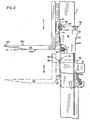
- By way of example, one way of carrying out the invention is described in detail below with reference to the accompanying drawings which illustrate a lift truck provided with a light assembly in accordance with one preferred embodiment. In said drawings:-
- Figure 1 is a partial extended side view of the lift truck which has a mast, load carriage and load forks and it shows the position of the light assembly when supportably mounted on the mast while the load carriage is in a lowered position;
- Figure 2 is a partial side view showing the position of the light assembly of Figure 1 when supportably mounted upon the load carriage while the carriage is in a raised position;
- Figure 3 is a partial front view taken along line 3-3 of Figure 1; and
- Figure 4 is an interior side view of the light assembly taken along line 4-4 of Figure 3.
- With reference to Figure 1, the lift truck designated generally as 10 is partially shown comprising a
main frame 12 mounted upon traction wheels such as 14 and having a vertically-extending load-lifting mast with anouter section 16 pivotally attached at the bottom thereof to theframe 12 so as to be capable of tilting forwardly and rearwardly in response to the extension or retraction of a hydraulic tilt cylinder, the rod portion of which is shown as 18. Normally one or more vertically- extensible inner mast sections such as 17 (Figures 2 and 3) are mounted telescopically within theouter section 16. Mounted upon theinner mast section 17 and vertically movable with respect thereto is a load-handling device designated generally as 20 which, in the embodiment shown, comprises aload carriage 22 withrollers 24 for permitting vertical movement with respect to theinner section 17, and transversely spaced, forwardly-extending load-engaging members comprising load forks such as 26 mounted thereon (only one of which is shown). Eachload fork 26 has an upwardly-facing load-engaging surface 26a, abottom surface 26b, and a forward end ortip 26c (Figure 2). - The light assembly provided is designated generally as 28 and comprises a
housing 30 in which is mounted alight source 32 which is preferably a reflector bulb capable of projecting light forwardly in a generally conical pattern. Thelight bulb 32 is energized through anelectrical line 34 which can be extended from or retracted into a spring-biased retractingreel 36 rotatably mounted within thehousing 30. Theline 34 is electrically coupled through a revolvingconnector 38 andelectrical lines bulb 32. Avariable resistor 46 is interjected betweenlines lift truck 10, which vary depending upon the particular battery equipment (not shown) utilized in the truck from which theconduit 34 draws its power. It will be appreciated that the provision of thereel 36 permits a wide range of vertical travel of thelight assembly 28 for purposes to be described hereafter. - The primary purpose of the light assembly is to aid the operator in the manipulation of the load-handling device (e.g. the
carriage 22 and forks 26) at positions thereof which are elevated above the operator. This is accomplished by mounting thelight assembly 28 upon the load-handling device, as shown in solid lines in Figure 2, and in particular on thecarriage 22, such that thelight source 32 is adjacent to the bottom of the load-handling device and rearwardly of theforward end 26c of the load-engaging member such as 26. In particular, when the load-engaging member is a fork such as 26 having an upwardly-facing load-engaging surface 26a, the light source should be at a level below that of the upwardly-facingsurface 26a so as not to be blocked by any load thereon. Preferably, thelight source 32 is at the same level as, or slightly below, thebottom 26b of the load-engaging member and is positioned in a vertical plane which intersects the load-engaging member longitudinally such that the light source is either directly beneath, or preferably directly behind, the load-engaging member. In this position, with the light source projecting light in a generally conical pattern and in a generally forward direction, a portion of the light will be intercepted by the load-engaging member 26 so as to project a shadow of the load-engaging member forwardly against a load stack, which shadow is accurately indicative of the vertical elevation of the load-engaging member 26. When located rearwardly of the entire load-engaging member as shown in Figure 2, thelight assembly 28 is positioned transversely outwardly of theouter mast section 16. - It should be appreciated that, while the position of the light source as depicted in Figure 2, i.e. directly behind the load-
engaging member 26 and at a level at or below the bottom of the load-engaging member, is considered to be the most advantageous, substantially equivalent results could be obtained by placing the light source in other positions adjacent the bottom of the load-handling device so as not to be blocked by the load, such as transversely to one side of the load-engaging member at an elevation below that of the upwardly-facing load-engaging surface 26a, and it is intended that such other equivalent positions be included within the scope of the invention as defined in the appended claims. - It will be noted that, because of the low mounting position of the
light assembly 28 on thecarriage 22 so as to be effective in performance of the above-described elevation- indicating function, at least a portion of the light assembly extends downward to or below the bottom of the load-engaging member 26 as depicted in Figure 2. To prevent damage to the light assembly when the carriage is lowered, the mounting structure by which thelight assembly 28 is mounted on thecarriage 22 permits movement of thelight assembly 28 with respect to the carriage from the above-described operative low mounting position. With reference specifically to Figures 2-4, a horizontally-oriented crossbar 48 is provided at the upper forward corner of thelight assembly 28 extending between a pair of transversely-spacedflanges 50. When thelight assembly 28 is mounted upon thecarriage 22, thecrossbar 48 rests by force of gravity upon a transversely-oriented shoulder 52 of a carriage-mounted upwardly and rearwardlyslanting support member 54 which fits loosely between theflanges 50. Thus it will be seen that thelight assembly 28 may be lifted freely from theshoulder 52 and/or pivoted upwardly and rearwardly about the axis of the crossbar 48 (forward pivoting of the light assembly from the position shown in Figure 2 is prevented by the abutment of theflanges 50 against the rearwardly-facing surfaces of the carriage 22). - Although the mounting of the
light assembly 28 on thecarriage 22 in such a way that the light assembly may move with respect to the carriage will lessen the chance of damage to the light assembly when the carriage is fully lowered, it is preferable that an additional mounting feature be utilized to further reduce the chance of damage to the light assembly and, at the same time, provide an additional function for the light assembly. This additional mounting feature involves a structure by which thelight assembly 28 may be detached automatically from theload carriage 22 and attached to theouter mast section 16 in response to downward movement of thecarriage 22 below a predetermined position or elevation. In this regard, it will be noted that acrossbar 56, similar tocrossbar 48, is provided at the rear upper corner of thehousing 30 between transversely-spacedflanges 58. An upwardly-opening support yoke 60, aligned behind thecarriage support member 54 as shown in Figure 3, is connected to theouter mast section 16 by abracket 62 and fits loosely between theflanges 58 so that, upon downward movement of thecarriage 22, thecrossbar 56 becomes engaged with theyoke 60 when the carriage is at a predetermined elevation approximately level with the operator's horizontal line of sight. Upon further downward movement of the carriage theyoke 60 prevents further downward movement of thelight assembly 28, and accordingly theforward crossbar 48 disengages from the carriage-mountedsupport member 54. Thus, when the carriage reaches its fully-lowered position as depicted in full lines in Figure 1, thelight assembly 28 is nowhere near ground level where it can be damaged by contact with the floor or other obstacles. Rather the light assembly remains at a higher level attached to theouter section 16 of the mast as shown in Figure 1. - Moreover, the detachment of the
light assembly 28 from thecarriage 22 permits the light assembly to hang freely from thecrossbar 56. Since the center of gravity of thelight assembly 28 is horizontally forward of thecrossbar 56 when the light assembly is vertical, the light assembly automatically assumes a downwardly-tilted position as shown in Figure 1 so as to direct light more downwardly than when the light assembly was attached to thecarriage 22. This enables the light to perform the additional function of illuminating the area in front of the lift truck when the carriage is lowered, to aid the operator in the manipulation of loads and provide travelling illumination for operation in dimly lit areas. The elevated position of thelight assembly 28 when the carriage is lowered provides excellent illumination for these purposes even when a load is being carried upon theforks 26, since thelight source 32 will normally be above the load thereby preventing any blockage of the light. - Upon movement of the carriage in an up ward direction, the
support member 54 once more engages theforward crossbar 48 when the carriage reaches a predetermined elevation and lifts thelight assembly 28 from theyoke 60. Upon further elevation of the carriage, thelight assembly 28 assumes its low (relative to the carriage), untilted position as shown in Figure 2 for performance of its fork level indicating functions at higher carriage elevations. - The terms and expressions which have been employed in the foregoing specification are used therein as terms of description and not of limitation, and there is no intention, in the use of such terms and expressions, of excluding equivalents of the features shown and described or portions thereof, it being recognized that the scope of the invention is defined and limited or otherwise determined only by the terms of the appended claims.
Claims (12)
Applications Claiming Priority (2)
| Application Number | Priority Date | Filing Date | Title |
|---|---|---|---|
| US06/010,303 US4224657A (en) | 1979-02-08 | 1979-02-08 | Light assembly for positioning lift truck load-handling device |
| US10303 | 1979-02-08 |
Publications (2)
| Publication Number | Publication Date |
|---|---|
| EP0014586A1 EP0014586A1 (en) | 1980-08-20 |
| EP0014586B1 true EP0014586B1 (en) | 1983-08-31 |
Family
ID=21745125
Family Applications (1)
| Application Number | Title | Priority Date | Filing Date |
|---|---|---|---|
| EP80300338A Expired EP0014586B1 (en) | 1979-02-08 | 1980-02-06 | Lift truck with light assembly for positioning load-handling device |
Country Status (5)
| Country | Link |
|---|---|
| US (1) | US4224657A (en) |
| EP (1) | EP0014586B1 (en) |
| JP (1) | JPS55106830A (en) |
| CA (1) | CA1138843A (en) |
| DE (1) | DE3064670D1 (en) |
Families Citing this family (18)
| Publication number | Priority date | Publication date | Assignee | Title |
|---|---|---|---|---|
| US4727962A (en) * | 1986-09-29 | 1988-03-01 | Caterpillar Inc. | Movable sensing apparatus |
| US5079864A (en) * | 1990-08-21 | 1992-01-14 | James Roy | Brush rake |
| US5586620A (en) * | 1995-05-12 | 1996-12-24 | Crown Equipment Corporation | Remote viewing apparatus for fork lift trucks |
| US6150938A (en) * | 1998-09-09 | 2000-11-21 | Sower; Forrest D. | Laser lighting assembly mounted on a forklift to project a light beam parallel to and in the same plane as a fork and utilized to accurately direct the fork into a fork receiving volume of a pallet, thereby avoiding any fork damage to a load on a pallet |
| JP2000226199A (en) | 1999-02-04 | 2000-08-15 | Nippon Yusoki Co Ltd | Forklift |
| JP2001226092A (en) * | 2000-02-10 | 2001-08-21 | Nippon Yusoki Co Ltd | Forklift |
| DE10055264A1 (en) * | 2000-11-08 | 2002-05-23 | Still Gmbh | Industrial truck with a lifting device and a work light |
| US7422408B2 (en) * | 2004-07-21 | 2008-09-09 | The Braun Corporation | Lighted vehicle access system and method |
| WO2013059151A1 (en) | 2011-10-19 | 2013-04-25 | Crown Equipment Corporation | Selecting objects within a vertical range of one another corresponding to pallets in an image scene |
| DE102012106990A1 (en) * | 2012-07-31 | 2014-02-06 | Linde Material Handling Gmbh | Driver assistance device for an industrial truck and industrial truck |
| AU2016205036B2 (en) * | 2015-01-09 | 2019-12-19 | J.W. Speaker Corporation | Tracking and lighting systems and methods for a vehicle |
| US20160272109A1 (en) * | 2015-03-20 | 2016-09-22 | Robert William Harrison | Linear flexible led fixture for lift trucks |
| US9990535B2 (en) | 2016-04-27 | 2018-06-05 | Crown Equipment Corporation | Pallet detection using units of physical length |
| KR102053490B1 (en) * | 2016-12-28 | 2019-12-06 | 주식회사 두산 | Light control device of forklift |
| JP6606133B2 (en) * | 2017-07-31 | 2019-11-13 | 本田技研工業株式会社 | snowblower |
| US12304790B1 (en) | 2021-07-20 | 2025-05-20 | Shaw Industries Group, Inc. | Clamp adapter for lift vehicle to facilitate lifting of malleable objects |
| CN116835483A (en) * | 2022-03-25 | 2023-10-03 | 物流及供应链多元技术研发中心有限公司 | Remote control material handling system and material handling vehicle |
| AU2025202100A1 (en) * | 2024-03-29 | 2025-10-16 | The Raymond Corporation | Lighting accessory for a material handling vehicle |
Family Cites Families (10)
| Publication number | Priority date | Publication date | Assignee | Title |
|---|---|---|---|---|
| US1859349A (en) * | 1930-08-11 | 1932-05-24 | William E Thibodeaux | Lighting system for automobile lifts |
| US2098419A (en) * | 1935-12-11 | 1937-11-09 | Handley Joseph Done | Motor vehicle hoist |
| US3119501A (en) * | 1961-10-10 | 1964-01-28 | Jerome H Lemelson | Automatic warehousing system |
| GB1124901A (en) * | 1965-02-03 | 1968-08-21 | Triax Co | Controls for material handling apparatus |
| US3672470A (en) * | 1969-11-26 | 1972-06-27 | Eaton Yale & Towne | Photoelectric control for load handling device |
| AU450936B2 (en) * | 1970-10-28 | 1974-07-25 | Clark Equipment Company | Light projection system for positioning a vehicular device |
| DE2254012A1 (en) * | 1972-11-04 | 1974-05-16 | Clark Equipment Co | LIGHT REFERENCE SYSTEM TO HELP THE OPERATING STAFF IN THE POSITIONING OF LOAD LIFTING DEVICES AND THE LIKE |
| US3934134A (en) * | 1975-03-03 | 1976-01-20 | J. I. Case Company | Lamp mounting for a material-handling tractor |
| DE2622075A1 (en) * | 1976-05-18 | 1977-12-01 | Lansing Gmbh | Forklift truck stacking accessory - has detectors indicating upwards or downwards load on forks or no load |
| SE7804927L (en) * | 1978-04-28 | 1979-10-29 | Volvo Ab | DEVICE FOR ORIENTATING, FOR EXAMPLE, A LIFTING RELATION IN RELATION TO A LOAD |
-
1979
- 1979-02-08 US US06/010,303 patent/US4224657A/en not_active Expired - Lifetime
-
1980
- 1980-01-18 CA CA000343962A patent/CA1138843A/en not_active Expired
- 1980-02-06 JP JP1256880A patent/JPS55106830A/en active Pending
- 1980-02-06 DE DE8080300338T patent/DE3064670D1/en not_active Expired
- 1980-02-06 EP EP80300338A patent/EP0014586B1/en not_active Expired
Also Published As
| Publication number | Publication date |
|---|---|
| CA1138843A (en) | 1983-01-04 |
| US4224657A (en) | 1980-09-23 |
| EP0014586A1 (en) | 1980-08-20 |
| DE3064670D1 (en) | 1983-10-06 |
| JPS55106830A (en) | 1980-08-16 |
Similar Documents
| Publication | Publication Date | Title |
|---|---|---|
| US4224657A (en) | Light assembly for positioning lift truck load-handling device | |
| AU707036B2 (en) | Remote viewing apparatus for fork lift trucks | |
| CA1239620A (en) | Forklift attachment | |
| US4927315A (en) | Vehicle lifting and towing apparatus | |
| CA1263949C (en) | Forklift variable reach mechanism | |
| CA2144886A1 (en) | Video camera guidance system for forklifts | |
| US2493750A (en) | Fork lift truck with boom | |
| US3335879A (en) | Side carrying lift truck | |
| US4047750A (en) | Overhead guard-battery ballast | |
| US2915144A (en) | Free lift truck | |
| DE102009006175B4 (en) | Industrial truck with lighting equipment and method for operating the industrial truck | |
| GB2033871A (en) | Improvements in or relating to lifting trucks | |
| US3472341A (en) | Lift truck with telescopic mast | |
| EP1457456B1 (en) | Forklift truck | |
| EP0592234B1 (en) | Improvements in load handling vehicles | |
| US3356238A (en) | Box loader | |
| WO1988006567A1 (en) | Device in a fork truck | |
| EP0086665A1 (en) | Conveying apparatus | |
| US3460699A (en) | Movable upright assembly with a laterally and pivotally mounted carrier | |
| JPH0270698A (en) | Forklift provided with sinking fork | |
| JPS5931676Y2 (en) | Winch device for forklift truck | |
| JPH0570094A (en) | Picking device for industrial vehicle | |
| EP0155119A2 (en) | Container and lifting mechanism | |
| CN114920172B (en) | Multifunctional reversed loading and unloading vehicle with changeable wheel track | |
| CN211223800U (en) | Ship mounting rack for container transportation |
Legal Events
| Date | Code | Title | Description |
|---|---|---|---|
| PUAI | Public reference made under article 153(3) epc to a published international application that has entered the european phase |
Free format text: ORIGINAL CODE: 0009012 |
|
| AK | Designated contracting states |
Designated state(s): DE FR GB IT NL |
|
| 17P | Request for examination filed |
Effective date: 19810122 |
|
| ITF | It: translation for a ep patent filed | ||
| GRAA | (expected) grant |
Free format text: ORIGINAL CODE: 0009210 |
|
| AK | Designated contracting states |
Designated state(s): DE FR GB IT NL |
|
| PG25 | Lapsed in a contracting state [announced via postgrant information from national office to epo] |
Ref country code: NL Effective date: 19830831 |
|
| REF | Corresponds to: |
Ref document number: 3064670 Country of ref document: DE Date of ref document: 19831006 |
|
| ET | Fr: translation filed | ||
| PGFP | Annual fee paid to national office [announced via postgrant information from national office to epo] |
Ref country code: DE Payment date: 19831219 Year of fee payment: 5 |
|
| PGFP | Annual fee paid to national office [announced via postgrant information from national office to epo] |
Ref country code: FR Payment date: 19831220 Year of fee payment: 5 |
|
| NLV1 | Nl: lapsed or annulled due to failure to fulfill the requirements of art. 29p and 29m of the patents act | ||
| PLBE | No opposition filed within time limit |
Free format text: ORIGINAL CODE: 0009261 |
|
| STAA | Information on the status of an ep patent application or granted ep patent |
Free format text: STATUS: NO OPPOSITION FILED WITHIN TIME LIMIT |
|
| 26N | No opposition filed | ||
| GBPC | Gb: european patent ceased through non-payment of renewal fee | ||
| PG25 | Lapsed in a contracting state [announced via postgrant information from national office to epo] |
Ref country code: FR Free format text: LAPSE BECAUSE OF NON-PAYMENT OF DUE FEES Effective date: 19851031 |
|
| PG25 | Lapsed in a contracting state [announced via postgrant information from national office to epo] |
Ref country code: DE Effective date: 19851101 |
|
| REG | Reference to a national code |
Ref country code: FR Ref legal event code: ST |
|
| PG25 | Lapsed in a contracting state [announced via postgrant information from national office to epo] |
Ref country code: GB Effective date: 19881118 |