EP0014128A1 - A device to make an electrical and thermal contact between several metallic surfaces, and utilisation thereof - Google Patents
A device to make an electrical and thermal contact between several metallic surfaces, and utilisation thereof Download PDFInfo
- Publication number
- EP0014128A1 EP0014128A1 EP80400058A EP80400058A EP0014128A1 EP 0014128 A1 EP0014128 A1 EP 0014128A1 EP 80400058 A EP80400058 A EP 80400058A EP 80400058 A EP80400058 A EP 80400058A EP 0014128 A1 EP0014128 A1 EP 0014128A1
- Authority
- EP
- European Patent Office
- Prior art keywords
- frame
- wire
- armature
- axis
- thermal contact
- Prior art date
- Legal status (The legal status is an assumption and is not a legal conclusion. Google has not performed a legal analysis and makes no representation as to the accuracy of the status listed.)
- Granted
Links
Images


Classifications
-
- H—ELECTRICITY
- H01—ELECTRIC ELEMENTS
- H01P—WAVEGUIDES; RESONATORS, LINES, OR OTHER DEVICES OF THE WAVEGUIDE TYPE
- H01P1/00—Auxiliary devices
- H01P1/24—Terminating devices
- H01P1/28—Short-circuiting plungers
-
- H—ELECTRICITY
- H01—ELECTRIC ELEMENTS
- H01J—ELECTRIC DISCHARGE TUBES OR DISCHARGE LAMPS
- H01J23/00—Details of transit-time tubes of the types covered by group H01J25/00
- H01J23/02—Electrodes; Magnetic control means; Screens
- H01J23/027—Collectors
- H01J23/033—Collector cooling devices
Abstract
Le procédé selon l'invention consiste à enrouler un fil métallique (1), sensiblement en hélice, à la fois autour d'une armature (2), constituée par une bande flexible, et autour de deux baguettes (3), disposées parallèlement à l'axe de l'armature OO' et de part et d'autre de l'armature. Les baguettes (3) sont supprimées lorsque le fil métallique est enroulé. L'armature (2) comporte des moyens limitant le déplacement du fil selon l'axe de l'armature (OO') qui est confondu avec l'axe de l'hélice selon laquelle le fil est enroulé. Ces moyens sont constitués par deux séries d'encoches (4 et 5), réalisées dans le sens de la longueur, sur deux bords opposés de la bande constituant l'armature. Les dispositifs obtenus par le procédé selon l'invention trouvent leur application dans le domaine des hyperfréquences.The method according to the invention consists in winding a metal wire (1), substantially helically, both around a frame (2), constituted by a flexible strip, and around two rods (3), arranged parallel to the axis of the frame OO 'and on either side of the frame. The strips (3) are removed when the metal wire is wound. The frame (2) comprises means limiting the displacement of the wire along the axis of the frame (OO ') which coincides with the axis of the propeller along which the wire is wound. These means consist of two series of notches (4 and 5), made lengthwise, on two opposite edges of the strip constituting the frame. The devices obtained by the process according to the invention find their application in the field of microwave frequencies.
Description
La présente invention concerne un procédé de fabrication d'un dispositif assurant un contact électrique et thermique entre plusieurs surfaces métalliques. Elle concerne également le dispositif obtenu par ce procédé et l'application de ce dispositif au domaine des hyperfréquences notamment.The present invention relates to a method of manufacturing a device ensuring electrical and thermal contact between several metal surfaces. It also relates to the device obtained by this method and the application of this device to the microwave domain in particular.
Il est connu, dans l'art antérieur, de réaliser un contact électrique et thermique entre deux surfaces métalliques, qui peuvent être par exemple les surfaces de deux cylindres coaxiaux constituant deux connexions d'un tube électronique hyperfréquence de géométrie coaxiale, tels que les triodes et tétrodes de puissance, en utilisant des lames souples. Ces lames sont découpées dans des bandes d'un métal ayant un bon coefficient d'élasticité, puis cambrées, et éventuellement traitées thermiquement ; c'est le cas par exemple si on utilise des lames en bronze au béryllium dont l'élasticité est augmentée par le traitement thermique. Ces lames sont ensuite soudées sur l'une des surfaces, généralement dans une gorge creusée sur cette surface et destinée à retenir la soudure. L'autre surface est ensuite placée en contact avec les lames ; un contact électrique et thermique est ainsi réalisé entre les deux surfaces métalliques.It is known in the prior art to make electrical and thermal contact between two metal surfaces, which may for example be the surfaces of two coaxial cylinders constituting two connections of a microwave electronic tube of coaxial geometry, such as triodes and power tetrodes, using flexible blades. These blades are cut from strips of metal having a good coefficient of elasticity, then bent, and possibly heat treated; this is the case, for example, if beryllium bronze blades are used, the elasticity of which is increased by the heat treatment. These blades are then welded on one of the surfaces, generally in a groove dug on this surface and intended to retain the weld. The other surface is then placed in contact with the blades; an electrical and thermal contact is thus made between the two metal surfaces.
- Le contact par lames souples présente de nombreux inconvénients parmi lesquels on peut citer :
- - la grande surface de contact entre chaque lame et la surface en vis-à-vis, et le déplacement des points de contact d'une lame à l'autre, ce qui peut provoquer la création d'arcs électriques entre lames ;
- - la fragilité des lames qui sont détériorées si elles sont soumises à un glissement orthogonal à leur sens de flexion et qui ne permettent donc pas de réaliser un contact entre deux surfaces soumises à la fois à des mouvements de rotation et de translation ;
- - la difficulté de sa fabrication, il faut en effet prendre beaucoup de précautions lorsqu'on soude les lames pour ne pas leur faire perdre leur élasticité et leur revêtement protecteur ;
- - sa structure trop compacte (les lames ont généralement deux à trois millimètres de large et ne sont séparées que par un intervalle d'un millimètre environ) ; la ventilation du contact est donc diffile et nécessite l'utilisation de turbines très puissantes.
- - the large contact surface between each blade and the facing surface, and the displacement of the contact points from one blade to another, which can cause the creation of electric arcs between blades;
- - The fragility of the blades which are deteriorated if they are subjected to a slip orthogonal to their direction of flexion and which therefore do not allow contact to be made between two surfaces subjected to both rotational and translational movements;
- - the difficulty of its manufacture, it is indeed necessary to take a lot of precautions when welding the blades so as not to make them lose their elasticity and their protective coating;
- - its too compact structure (the blades are generally two to three millimeters wide and are only separated by an interval of about one millimeter); contact ventilation is therefore difficult and requires the use of very powerful turbines.
Il est également connu, dans l'art antérieur, de réaliser un contact électrique et thermique entre deux surfaces métalliques en utilisant un ressort, logé dans une gorge creusée sur l'une des surfaces et maintenu au fond de la gorge par un lien élastique. L'autre surface est ensuite placée en contact avec le ressort, un contact électrique et .thermiαue est ainsi réalisé entre les deux surfaces métalliques.It is also known, in the prior art, to make electrical and thermal contact between two metal surfaces using a spring, housed in a groove hollowed out on one of the surfaces and held at the bottom of the groove by an elastic link. The other surface is then placed in contact with the spring, an electrical contact and .thermiαue is thus produced between the two metal surfaces.
Le contact par ressort présente, par rapport au contact par lames souples, l'avantage d'être ponctuel et de ne pas nécessiter de soudure, de plus, sa ventilation est facile car il est constitué de fil et non de plaque métalliques. Par contre, le contact par ressort présente un grand inconvénient qui est sa fragilité. En effet, il se détériore facilement, notamment lors de sa mise en place, et en particulier les spires ne restent pas uniformément écartées. Le contact par ressort ne permet donc pas, comme le contact par lames souples, de réaliser un contact entre deux surfaces soumises à la fois à des mouvements de rotation et de translation.Contact by spring has, compared to contact with flexible blades, the advantage of being punctual and of not requiring welding, moreover, its ventilation is easy because it consists of wire and not of metal plate. On the other hand, the spring contact has a great disadvantage which is its brittleness. Indeed, it deteriorates easily, especially during its installation, and in particular the turns do not remain uniformly apart. Contact by spring therefore does not allow, like contact by flexible blades, to make contact between two surfaces subjected to both rotational and translational movements.
La présente invention concerne un procédé de fabrication d'un dispositif assurant un contact électrique et thermique entre plusieurs surfaces métalliques qui consiste à enrouler, au moins un fil métallique, sensiblement en hélice, autour d'une armature qui comporte des moyens limitant le déplacement du fil selon l'axe de l'armature, qui est confondu avec l'axe de l'hélice selon laquelle le fil est enroulé ; les diverses surfaces métalliques sont en contact avec le fil métallique.The present invention relates to a method of manufacturing a device ensuring electrical and thermal contact between several metal surfaces which consists in winding, at least one metal wire, substantially helically, around a frame which comprises means limiting the movement of the wire along the axis of the armature, which coincides with the axis of the propeller along which the wire is wound; the various metal surfaces are in contact with the metal wire.
Le dispositif assurant un contact électrique et thermique entre plusieurs surfaces métalliques, obtenu par le procédé selon l'invention, présente, comme le contact par ressort connu dans l'art antérieur, l'avantage d'être ponctuel, de ne pas nécessiter de soudure et d'être facile à ventiler. Le dispositif selon l'invention présente en outre, par rapport au contact par ressort, l'avantage essentiel de ne pas être facilement déformable car les moyens qui limitent le déplacement du fil selon l'axe de l'armature maintiennent un écartement sensiblement uniforme entre spires. Le dispositif selon l'invention peut donc être aisément utilisé pour réaliser le contact entre plusieurs surfaces métalliques soumises à la fois à des mouvements de rotation et de translation.The device ensuring electrical and thermal contact between several metal surfaces, obtained by the method according to the invention, has, like the spring contact known in the prior art, the advantage of being punctual, of not requiring welding and be easy to ventilate. The device according to the invention also has, compared to the spring contact, the essential advantage of not being easily deformable because the means which limit the movement of the wire along the axis of the armature maintain a substantially uniform spacing between turns. The device according to the invention can therefore be easily used to make contact between several metal surfaces subjected to both rotational and translational movements.
D'autres objets, caractéristiques et résultats de l'invention ressortiront de la description suivante, donnée à titre d'exemple non limitatif, et illustrée par les figures annexées qui représentent :
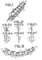
- - la figure 1, une vue en perspective, illustrant le procédé de fabrication selon l'invention, d'un dispositif assurant un contact électrique et thermique entre plusieurs surfaces métalliques ;
- - les figures 2a, b, c, d, e, f, des vues de face de dispositifs assurant un contact électrique et thermique entre plusieurs surfaces métalliques illustrant différents modes d'application du procédé de fabrication selon l'invention ;
- - les figures 3, 4, 5, et 6, des vues de face et en perspective de différents modes de réalisation de dispositifs assurant un contact électrique et thermique entre plusieurs surfaces métalliques obtenus par le procédé de fabrication selon l'invention ;
- - les figures 7 à 14, des exemples d'application d'un dispositif assurant un contact électrique et thermique entre plusieurs surfaces métalliques obtenu par le procédé de fabrication selon l'invention.
- - Figure 1, a perspective view, illustrating the manufacturing method according to the invention, of a device ensuring electrical and thermal contact between several metal surfaces;
- - Figures 2a, b, c, d, e, f, front views of devices ensuring electrical and thermal contact between several metal surfaces illustrating different modes of application of the manufacturing method according to the invention;
- - Figures 3, 4, 5, and 6, front and perspective views of different embodiments of devices ensuring electrical and thermal contact between several metal surfaces obtained by the manufacturing process according to the invention;
- - Figures 7 to 14, examples of application of a device ensuring electrical and thermal contact between several metal surfaces obtained by the manufacturing process according to the invention.
Sur les différentes figures, les mêmes repères désignent les mêmes éléments, mais, pour des raisons de clarté les cotes et proportions des différents éléments n'ont pas été respectées.In the different figures, the same references designate the same elements, but, for reasons of clarity, the dimensions and proportions of the different elements have not been respected.
La figure 1 représente une vue en perspective, illustrant le procédé de fabrication selon l'invention; d'un dispositif assurant un contact électrique et thermique entre plusieurs surfaces métalliques. Un fil métallique 1 est enroulé, sensiblement en hélice, à la fois autour d'une armature 2, qui comporte des moyens limitant le déplacement du fil selon l'axe de l'armature 00', qui est confondu avec l'axe de l'hélice selon laquelle le fil est enroulé, et autour de deux baguettes 3 disposées parallèlement à l'axe de l'armature 00'.Figure 1 shows a perspective view illustrating the manufacturing method according to the invention; a device ensuring electrical and thermal contact between several metal surfaces. A
Sur la figure 1, l'armature est constituée par une bande flexible et les moyens limitant le déplacement du fil selon l'axe de l'armature sont constitués par deux séries d'encoches 4 et 5, réalisées dans le sens de la longueur, sur deux bords opposés de la bande flexible constituant l'armature. Le fil métallique 1 est introduit dans les encoches. Les encoches des deux séries 4 et 5 peuvent se faire face, comme représenté sur la figure 1, ou non.In FIG. 1, the armature is constituted by a flexible strip and the means limiting the movement of the wire along the axis of the armature are constituted by two series of notches 4 and 5, produced lengthwise, on two opposite edges of the flexible strip constituting the reinforcement. The
Les diverses surfaces métalliques, entre lesquelles le dispositif selon l'invention assure un contact électrique et thermique, ne sont pas représentées sur les figures 1 à 6. Ces surfaces sont bien entendu en contact avec le fil métallique 1.The various metallic surfaces, between which the device according to the invention provides electrical and thermal contact, are not shown in FIGS. 1 to 6. These surfaces are of course in contact with the
Les figures 2a, b, c, d, e, f, représentent des vues de face de dispositifs assurant un contact électrique et thermique entre plusieurs surfaces métalliques et illustrant différents modes d'application du procédé de fabrication selon l'invention. Sur ces figures, les baguettes 3 sont, comme sur la figure 1, disposées parallèlement à l'axe de l'armature 00', mais leur nombre, leur taille et leur position respectives varient.Figures 2a, b, c, d, e, f, show front views of devices ensuring electrical and thermal contact between several metal surfaces and illustrating different modes of application of the manufacturing method according to the invention. In these figures, the
Sur la figure 2a, deux baguettes 3, de tailles différentes, sont disposées de façon symétrique de part et d'autre de l'armature, le dispositif obtenu est donc dissymétrique.In FIG. 2a, two
Sur la figure 2b, deux baguettes identiques sont disposées de façon symétrique de part et d'autre de l'armature et à une des extrémités de l'armature, le dispositif obtenu est donc sensiblement triangulaire.In FIG. 2b, two identical rods are arranged symmetrically on either side of the frame and at one of the ends of the frame, the device obtained is therefore substantially triangular.
Sur la figure 2c, deux baguettes identiques sont disposées de part et d'autre de l'armature mais à des niveaux différents, le dispositif obtenu est incliné.In Figure 2c, two identical rods are arranged on either side of the frame but at different levels, the device obtained is inclined.
Sur la figure 2d, quatre baguettes identiques sont disposées de part et d'autre de l'armature. Les baguettes occupent deux à deux des positions symétriques par rapport à r'armature et le dispositif est hexagonal.In FIG. 2d, four identical rods are arranged on either side of the frame. The rods occupy two by two symmetrical positions relative to the armature and the device is hexagonal.
Sur la figure 2e, une seule baguette est utilisée.In Figure 2e, only one rod is used.
Sur la figure 2f, comme sur la figure 2d, quatre baguettes identiques sont utilisées et sont réparties de part et d'autre de l'armature. Les baguettes ont deux à deux une position symétrique par rapport à l'armature et chaque groupe de deux baguettes se trouve situé à une extrémité de l'armature. Le dispositif obtenu est donc sensiblement rectangulaire. Il peut être, en outre, soumis à un traitement thermique ou mécanique qui lui donne une forme sensiblement en bobine, comme représenté sur la figure 2f.In FIG. 2f, as in FIG. 2d, four identical rods are used and are distributed on either side of the frame. The rods have two by two a symmetrical position relative to the frame and each group of two rods is located at one end of the frame. The device obtained is therefore substantially rectangular. It can also be subjected to a heat or mechanical treatment which gives it a substantially coil shape, as shown in FIG. 2f.
Le procédé selon l'invention s'applique quel que soit le nombre de baguettes 3, il s'applique aussi lorsque le fil est enroulé uniquement autour de l'armature 2, c'est-à-dire lorsqu'aucune baguette n'est utilisée.The method according to the invention applies regardless of the number of
La figure 3 représente une vue de face d'un mode de réalisation d'un dispositif assurant un contact électrique et thermique entre plusiseurs surfaces métalliques qui est obtenu par le procédé selon l'invention.FIG. 3 represents a front view of an embodiment of a device ensuring electrical and thermal contact between several metal surfaces which is obtained by the process according to the invention.
Sur la figure 3, comme sur la figure 1, l'armature 2 est constituée par une bande flexible, mais l'armature représentée sur la figure 3 comporte dans le sens de la longueur, sur deux bords opposés, deux séries de fentes 8 et 9, perpendiculaires à l'axe de l'armature 00'. Les fentes des deux séries 8 et 9 alternent sur l'armature.In FIG. 3, as in FIG. 1, the
Le dispositif représenté sur la figure 3 peut être utilisé à plat en forme de disque, les fentes de l'une des séries, la série 8 sur la figure 3, se recouvrent, alors que les fentes de l'autre série, la série 9 sur la figure 3, s'écartent, alors que le dispositif représenté sur la figure 1 ne peut être utilisé qu'enroulé autour d'un cylindre ou sous forme de bande rectangulaire.The device shown in Figure 3 can be used flat disc-shaped, the slots of one of the series, the
Sur la figure 3, les moyens limitant le déplacement du fil selon l'axe de l'armature sont constitués par deux séries d'orifices, 6 et 7, percés sur la plaque constituant l'armature 2, dans le sens de la longueur. Le fil métallique 1 est introduit dans ces orifices.In FIG. 3, the means limiting the movement of the wire along the axis of the armature consist of two series of orifices, 6 and 7, drilled on the plate constituting the
La figure 4 représente une vue en perspective d'un mode de réalisation d'un dispositif assurant un contact électrique et thermique entre plusieurs surfaces métalliques qui est obtenu par le procédé selon l'invention.FIG. 4 represents a perspective view of an embodiment of a device ensuring electrical and thermal contact between several metal surfaces which is obtained by the method according to the invention.
Sur la figure 4, l'armature 2 est constituée par une feuille découpée en forme d'anneau. Deux baguettes 3 sont disposées de part et d'autre de l'armature, ces baguettes sont également en forme d'anneau, elles sont exécutées en matière plastique ou en toute autre matière qui pourra être dissoute après bobinage.In FIG. 4, the
Sur la figure 4, les moyens limitant le déplacement du fil selon l'axe de l'armature 00' sont constitués par des ondulations 12, réalisées sur deux bords opposés de la plaque constituant l'armature et suivant l'axe de l'armature 00'. Le fil métallique est introduit dans les concavités 13 des ondulations. Sur la figure 4, deux fils métalliques 10 et 11 sont enroulés en hélice, de manière identique, et alternent sur l'armature. Le nombre de fils-métalliques peut être quelconque.In FIG. 4, the means limiting the movement of the wire along the axis of the armature 00 'consist of
La figure 5 représente une vue en perspective d'un autre mode de réalisation d'un dispositif assurant un contact électrique et thermique entre plusieurs surfaces métalliques qui est obtenu par le procédé selon l'invention. L'armature 2 est constituée par un fil enroulé, sensiblement en hélice, à spires jointives. Les moyens limitant le déplacement du fil selon l'axe de l'armature 00' sont constitués par un fil enroulé sensiblement en hélice 14, à spires non jointives, sur l'armature. Les hélices de l'armature et des moyens limitant le déplacement du fil peuvent être aplaties pour limiter l'encombrement en largeur du dispositif. Le fil métallique 1 assurant le contact électrique entre plusieurs surfaces métalliques est inséré dans l'espace compris entre deux spires consécutives et non jointives de l'hélice 14 constituant les moyens limitant le déplacement du fil.FIG. 5 represents a perspective view of another embodiment of a device ensuring electrical and thermal contact between several metal surfaces which is obtained by the method according to the invention. The
La figure 6 représente un autre mode de réalisation d'un dispositif assurant un contact électrique et thermique entre plusieurs surfaces métalliques qui est obtenu par le procédé selon l'invention.FIG. 6 represents another embodiment of a device ensuring electrical and thermal contact between several metal surfaces which is obtained by the process according to the invention.
Un fil métallique 23 est enroulé sensiblement en hélice à la fois autour de l'armature 2, qui est constituée sur cet exemple par une bande flexible, et autour d'au moins une première baguette disposée parallèlement à l'axe de l'armature 00', cette baguette n'est pas représentée sur la figure. On enroule ensuite un autre fil métallique 24, sensiblement en hélice, à la fois autour de l'armature 2 et d'au moins une deuxième baguette disposée parallèlement à l'axe de l'armature et de l'autre côté de l'armature par rapport à la première baguette. Le dispositif obtenu présente davantage de solidité et permet d'éviter que les déformations reçues par le fil métallique se trouvant d'un côté de l'armature soient transmises au fil métallique se trouvant de l'autre côté de l'armature.A
Le dispositif assurant un contact électrique et thermique obtenu par le procédé selon l'invention est utilisé dans de nombreuses applications, notamment dans le domaine des hyperfréquences. Ce dispositif est ainsi utilisé dans les tubes électroniques hyperfréquence de géométrie coaxiale, tels que les triodes et tétrodes de puissance qu'utilisent les émetteurs de radio-diffusion et de télévision, les radars et les générateurs de haute fréquence industrielle, pour assurer un contact électrique et thermique entre les surfaces de deux cylindres coaxiaux constituant deux connexions d'un tube. Le dispositif peut être alors logé dans une gorge creusée à la surface de l'un des deux cylindres. Il peut être aussi "fixé à la' surface de l'un des deux cylindres, soit comme représenté sur la figure 7, qui est une vue en perspective éclatée, par des pattes 27 prévues sur la surface 28 qui pénètrent dans des orifices 29, oblongs, percés sur l'armature 2, orthogonalement à l'axe 00' de l'armature, soit par des pattes 30 découpées sur l'armature 2, comme représenté sur la figure 8, qui est une vue en perspective de l'armature, ces pattes 30 pénètrent alors dans des orifices prévus à la surface de l'un des deux cylindres.The device ensuring electrical and thermal contact obtained by the method according to the invention is used in numerous applications, in particular in the field of microwave frequencies. This device is thus used in microwave electronic tubes of coaxial geometry, such as power triodes and tetrodes used by radio and television transmitters, radars and industrial high frequency generators, to ensure electrical contact. and thermal between the surfaces of two coaxial cylinders constituting two connections of a tube. The device can then be housed in a groove hollowed out on the surface of one of the two cylinders. It can also be "fixed to the surface of one of the two cylinders, either as shown in FIG. 7, which is an exploded perspective view, by means of
Ce dispositif peut être aussi utilisé, comme représenté sur la figure 9, pour réaliser un contact électrique entre deux parois 15 et 16 d'une cavité coaxiale hyperfréquence. Le dispositif 20 sert alors de piston. Il est entraîné en translation, comme représenté par une double flèche sur la figure 9, par une tige de commande.This device can also be used, as shown in FIG. 9, to make an electrical contact between two
Afin que le dispositif 20 assure le contact entre les parois 15 et 16, quelles que soient les variations du diamètre de ces parois et leur excentration, il faut :
- - soit mettre en
place le dispositif 20 en forçant les spires de l'hélice, selon laquelle le fil 1 est enroulé, à se mettre en épi, par rapport à l'armature 2, comme représenté sur la figure 10, qui est une vue de dessus du dispositif 20 assurant un contact électrique entre les parois 15et 16 d'une cavité coaxiale hyperfréquence, et qui est représenté vu en perspective sur la figure 9 ; - - soit utiliser un dispositif tel que celui représenté sur la figure 6 qui est réalisé en deux étapes et qui présente une grande souplesse d'utilisation.
- - Either set up the
device 20 by forcing the turns of the propeller, according to which thewire 1 is wound, to stand on the cob, relative to theframe 2, as shown in Figure 10, which is a view from above thedevice 20 ensuring electrical contact between thewalls - - Either use a device such as that shown in Figure 6 which is carried out in two stages and which has great flexibility of use.
Pour réaliser un contact électrique entre deux parois 15 et 16 d'une cavité coaxiale hyperfréquence, on peut aussi utiliser, comme'représenté sur la figure 11 qui est une vue en perspective, deux dispositifs 20, obtenus par le procédé selon l'invention, et montés dans deux gorges 31 situées de part et d'autre d'un piston 32. Les dispositifs 20 sont reliés au piston par leur armature 2. Il est possible d'utiliser pour loger les dispositifs 20 des gorges 31 de forme rectangulaire, ou de forme triangulaire, comme représenté sur la figure 11. Les gorges de forme triangulaire présentent l'avantage lorsque les dispositifs 20 sont sensiblement en losange, comme représenté sur la figure 11, de permettre une très bonne ventilation des contacts grâce à l'espace compris entre chaque dispositif 20 et le piston 32. De plus, avec les gorges triangulaires, les dispositifs 20 sont en contact avec deux côtés des gorges et suivent donc les moindres déplacements du piston 32, ce qui n'est pas le cas pour les gorges rectangulaires avec lesquelles il est difficile d'effectuer un réglage fin de la position du piston, car les dispositifs 20 n'assurent pas un bon contact avec le piston, d'autant plus qu'il est nécessaire de prévoir un jeu èntre l'armature et le piston pour laisser l'armature libre de changer de dimensions. Le piston est bien entendu mobile en translation comme représenté par une double flèche sur la figure 11.To make electrical contact between two
Le dispositif obtenu par le procédé selon l'invention peut être utilisé pour réaliser un contact électrique et thermique entre plusieurs surfaces métalliques, quatre surfaces métalliques, par exemple, pour le dispositif sensiblement hexagonal, représenté vu de face sur la figure 12.The device obtained by the method according to the invention can be used to make electrical and thermal contact between several metallic surfaces, four metallic surfaces, for example, for the substantially hexagonal device, shown seen from the front in Figure 12.
Les quatre surfaces A, B, C, D, s'appuient sur les côtés a, b, c, d, de l'hexagone, ces surfaces A, B, C, D, peuvent être ou non animées de mouvements de rotation.The four surfaces A, B, C, D, are based on the sides a, b, c, d, of the hexagon, these surfaces A, B, C, D, may or may not be animated with rotational movements.
Le dispositif obtenu par le procédé selon l'invention peut être logé, comme représenté sur la figure 13, dans une gorge hélicoïdale 21 prévue à la surface de l'une des deux pièces entre lesquelles le dispositif 20 assure un contact électrique et thermique. Cette gorge 21 permet d'accroître la surface du contact réalisée par le dispositif 20 entre les deux pièces 18 et 19. Sur la figure 13, la pièce 19 comporte des ailettes de refroidissement 22. Le dispositif 20 représenté sur la figure 13 assure le contact entre les pièces 18 et 19 qui peuvent être soumises à la fois à des mouvements de rotation et de translation.The device obtained by the method according to the invention can be housed, as shown in FIG. 13, in a
Il est également possible de réaliser un filetage de la pièce 18. Les deux pièces 18 et 19 peuvent alors se visser l'une dans l'autre par l'intermédiaire du dispositif 20 et le contact ainsi réalisé est fixe.It is also possible to make a thread of the
Il est également possible de superposer plusieurs dispositifs 20 afin d'accroître la surface du contact réalisé entre plusieurs pièces métalliques.It is also possible to superimpose
Un exemple de réalisation non limitatif de l'objet de l'invention, illustré par la figure 14, a donné les résultats suivants :
- Le dispositif 20 comporte une armature 2 constituée d'une bande flexible en bronze au béryllium de 0,2 mm d'épaisseur. L'armature des dispositifs selon l'invention est généralement métallique, ce qui permet de diminuer la self de contact entre le fil métallique et l'armature, mais on doit signaler que l'armature peut être aussi réalisée en matériaux isolants, tels que du polytétrafluoroéthylène. Sur l'armature 2, on a donc bobiné, sensiblement en hélice, un fil métallique 1 en tungstène, de 0,33 mm de diamètre. Deux baguettes de mise en forme, cylindriques, de 2,5 mm de diamètre ont été utilisées pour bobiner le fil et ensuite supprimées. Le dispositif 20 est logé, comme représenté sur la figure 14, dans une gorge de hauteur h égale à 9 mm, creusée dans une pièce métallique 25.
Un piston 26 de diamètre D égal à 77 mm est en contact avec le dispositif 20. Ce piston peut se déplacer en rotation et en translation, comme indiqué sur la figure 14, par des flèches.
- The
device 20 comprises anarmature 2 consisting of a flexible strip of beryllium bronze 0.2 mm thick. The framework of the devices according to the invention is generally metallic, which reduces the contact inductance between the metal wire and the frame, but it should be noted that the frame can also be made of insulating materials, such as polytetrafluoroethylene. On theframe 2, ametallic wire 1 made of tungsten, 0.33 mm in diameter, was therefore wound, substantially helically. Two forming rods, cylindrical, 2.5 mm in diameter were used to wind the wire and then removed. Thedevice 20 is housed, as shown in FIG. 14, in a groove of height h equal to 9 mm, hollowed out in ametal part 25. Apiston 26 of diameter D equal to 77 mm is in contact with thedevice 20. This piston can move in rotation and in translation, as indicated on figure 14, by arrows.
Un courant de 200 Ampères est établi entre les pièces 25 et 26, qui sont en laiton. La chute de tension enregistrée n'est que de 28 millivolts, alors qu'elle serait d'au moins 50 millivolts si le contact entre les surfaces métalliques des pièces 25 et 26 était établi par des dispositifs selon l'art antérieur. Enfin, après une heure et demie de fonctionnement, la température des pièces 25 et 26 ne dépasse pas 40 degrés Celcius, car le dispositif selon l'invention permet de réaliser aisément une bonne ventilation.A current of 200 amperes is established between
Claims (18)
Applications Claiming Priority (2)
| Application Number | Priority Date | Filing Date | Title |
|---|---|---|---|
| FR7902282A FR2448221A1 (en) | 1979-01-30 | 1979-01-30 | METHOD FOR MANUFACTURING A DEVICE PROVIDING AN ELECTRICAL AND THERMAL CONTACT BETWEEN SEVERAL METAL SURFACES, DEVICE OBTAINED BY THIS PROCESS AND APPLICATION OF THIS DEVICE |
| FR7902282 | 1979-01-30 |
Publications (2)
| Publication Number | Publication Date |
|---|---|
| EP0014128A1 true EP0014128A1 (en) | 1980-08-06 |
| EP0014128B1 EP0014128B1 (en) | 1984-03-21 |
Family
ID=9221339
Family Applications (1)
| Application Number | Title | Priority Date | Filing Date |
|---|---|---|---|
| EP80400058A Expired EP0014128B1 (en) | 1979-01-30 | 1980-01-15 | A device to make an electrical and thermal contact between several metallic surfaces, and utilisation thereof |
Country Status (4)
| Country | Link |
|---|---|
| US (1) | US4488086A (en) |
| EP (1) | EP0014128B1 (en) |
| DE (1) | DE3067076D1 (en) |
| FR (1) | FR2448221A1 (en) |
Citations (4)
| Publication number | Priority date | Publication date | Assignee | Title |
|---|---|---|---|---|
| US2379047A (en) * | 1942-05-01 | 1945-06-26 | Bell Telephone Labor Inc | Bridging conductor |
| US2829352A (en) * | 1953-12-24 | 1958-04-01 | Varian Associates | Tunable waveguide short |
| US2932806A (en) * | 1958-12-02 | 1960-04-12 | Bomac Lab Inc | Broadband microwave window |
| US3255426A (en) * | 1964-03-09 | 1966-06-07 | Jesse L Butler | Stripline having two ground planes mechanically spaced by removable longitudinal electrical connectors disposed parallel to signal conductor |
Family Cites Families (2)
| Publication number | Priority date | Publication date | Assignee | Title |
|---|---|---|---|---|
| US3614518A (en) * | 1970-03-16 | 1971-10-19 | Varian Associates | Microwave tuner having sliding contactors |
| JPS5544404Y2 (en) * | 1974-05-09 | 1980-10-18 |
-
1979
- 1979-01-30 FR FR7902282A patent/FR2448221A1/en active Granted
-
1980
- 1980-01-15 EP EP80400058A patent/EP0014128B1/en not_active Expired
- 1980-01-15 DE DE8080400058T patent/DE3067076D1/en not_active Expired
-
1983
- 1983-01-28 US US06/462,106 patent/US4488086A/en not_active Expired - Lifetime
Patent Citations (4)
| Publication number | Priority date | Publication date | Assignee | Title |
|---|---|---|---|---|
| US2379047A (en) * | 1942-05-01 | 1945-06-26 | Bell Telephone Labor Inc | Bridging conductor |
| US2829352A (en) * | 1953-12-24 | 1958-04-01 | Varian Associates | Tunable waveguide short |
| US2932806A (en) * | 1958-12-02 | 1960-04-12 | Bomac Lab Inc | Broadband microwave window |
| US3255426A (en) * | 1964-03-09 | 1966-06-07 | Jesse L Butler | Stripline having two ground planes mechanically spaced by removable longitudinal electrical connectors disposed parallel to signal conductor |
Also Published As
| Publication number | Publication date |
|---|---|
| FR2448221A1 (en) | 1980-08-29 |
| US4488086A (en) | 1984-12-11 |
| FR2448221B1 (en) | 1982-04-30 |
| DE3067076D1 (en) | 1984-04-26 |
| EP0014128B1 (en) | 1984-03-21 |
Similar Documents
| Publication | Publication Date | Title |
|---|---|---|
| CA1111377A (en) | Electrode for ozone generating apparatus | |
| EP1145379B1 (en) | Antenna provided with an assembly of filtering materials | |
| WO2002044676A1 (en) | Method for making thermo-electric converters | |
| FR2616005A1 (en) | SUPERCONDUCTING WINDING WITH CONCENTRIC WINDING TEMPLATES EACH CARRYING A SUPERCONDUCTING WIRE IN A PROPELLER | |
| EP0373052A1 (en) | Support element for a transmission line, especially for a triplate line | |
| FR2530074A1 (en) | CYLINDRICAL FUSE | |
| EP0504776B1 (en) | Low loss coaxial cable | |
| FR3050488A1 (en) | ROTARY ACTUATOR USING TRACTION MEMORY MEMORY ALLOY WIRES | |
| EP0014128B1 (en) | A device to make an electrical and thermal contact between several metallic surfaces, and utilisation thereof | |
| EP0369910B1 (en) | Electrified ribbon for a fencing | |
| FR2529007A1 (en) | ELECTRICAL CABLE SUPPORTING VERY SEVERE CONDITIONS OF USE | |
| WO2020178535A1 (en) | Self-illuminated power cable with offset energy recovery system, and method of manufacturing same | |
| EP1314355A2 (en) | Electrical bird repellent device | |
| EP3935652A1 (en) | Low current self-illuminated power cable which retains flexibility, and method of manufacturing same | |
| WO1986005328A1 (en) | Method and device for the connection of a bundle of electric wires | |
| FR2589620A1 (en) | MULTIPISER CAPACITOR | |
| FR2579366A1 (en) | Capacitor with very high energy per unit volume and supervised self-healing | |
| EP1583461B1 (en) | Longitudinally-steerable structure | |
| CA1109533A (en) | Flexible electric cable with corrugated insulation, and related method of manufacture | |
| FR2473778A1 (en) | ELECTRODE PLATE FOR CAPACITOR | |
| EP0874374B1 (en) | Electrical resistance as resistive flexible belt and apparatus using said resistance | |
| CA1059610A (en) | Elongated continuous receiving structure_ | |
| CH620545A5 (en) | Method of manufacturing electrical resistors from a metal foil or film, application to obtaining thermoelectrical probes or strain gauges | |
| FR2691296A1 (en) | Coaxial cable with stiffened central conductor - is formed using crenellation or corrugation of inner conductor after stripping to make it more rigid | |
| CA2219449A1 (en) | Device for de-icing a current-carrying conductor |
Legal Events
| Date | Code | Title | Description |
|---|---|---|---|
| PUAI | Public reference made under article 153(3) epc to a published international application that has entered the european phase |
Free format text: ORIGINAL CODE: 0009012 |
|
| AK | Designated contracting states |
Designated state(s): DE GB IT NL |
|
| 17P | Request for examination filed | ||
| ITF | It: translation for a ep patent filed |
Owner name: JACOBACCI & PERANI S.P.A. |
|
| GRAA | (expected) grant |
Free format text: ORIGINAL CODE: 0009210 |
|
| AK | Designated contracting states |
Designated state(s): DE GB IT NL |
|
| REF | Corresponds to: |
Ref document number: 3067076 Country of ref document: DE Date of ref document: 19840426 |
|
| PLBE | No opposition filed within time limit |
Free format text: ORIGINAL CODE: 0009261 |
|
| STAA | Information on the status of an ep patent application or granted ep patent |
Free format text: STATUS: NO OPPOSITION FILED WITHIN TIME LIMIT |
|
| 26N | No opposition filed | ||
| ITTA | It: last paid annual fee | ||
| PGFP | Annual fee paid to national office [announced via postgrant information from national office to epo] |
Ref country code: NL Payment date: 19981214 Year of fee payment: 20 Ref country code: DE Payment date: 19981214 Year of fee payment: 20 |
|
| PGFP | Annual fee paid to national office [announced via postgrant information from national office to epo] |
Ref country code: GB Payment date: 19981216 Year of fee payment: 20 |
|
| PG25 | Lapsed in a contracting state [announced via postgrant information from national office to epo] |
Ref country code: GB Free format text: LAPSE BECAUSE OF EXPIRATION OF PROTECTION Effective date: 20000114 |
|
| PG25 | Lapsed in a contracting state [announced via postgrant information from national office to epo] |
Ref country code: NL Free format text: LAPSE BECAUSE OF EXPIRATION OF PROTECTION Effective date: 20000115 |
|
| REG | Reference to a national code |
Ref country code: GB Ref legal event code: PE20 Effective date: 20000114 |
|
| NLV7 | Nl: ceased due to reaching the maximum lifetime of a patent |
Effective date: 20000115 |