EP0012173B1 - Apparatus for picture processing with resolution conversion - Google Patents
Apparatus for picture processing with resolution conversion Download PDFInfo
- Publication number
- EP0012173B1 EP0012173B1 EP79103924A EP79103924A EP0012173B1 EP 0012173 B1 EP0012173 B1 EP 0012173B1 EP 79103924 A EP79103924 A EP 79103924A EP 79103924 A EP79103924 A EP 79103924A EP 0012173 B1 EP0012173 B1 EP 0012173B1
- Authority
- EP
- European Patent Office
- Prior art keywords
- output
- group
- pels
- signals
- sub
- Prior art date
- Legal status (The legal status is an assumption and is not a legal conclusion. Google has not performed a legal analysis and makes no representation as to the accuracy of the status listed.)
- Expired
Links
Images


Classifications
-
- H—ELECTRICITY
- H04—ELECTRIC COMMUNICATION TECHNIQUE
- H04N—PICTORIAL COMMUNICATION, e.g. TELEVISION
- H04N1/00—Scanning, transmission or reproduction of documents or the like, e.g. facsimile transmission; Details thereof
- H04N1/387—Composing, repositioning or otherwise geometrically modifying originals
- H04N1/393—Enlarging or reducing
- H04N1/3935—Enlarging or reducing with modification of image resolution, i.e. determining the values of picture elements at new relative positions
-
- G—PHYSICS
- G06—COMPUTING; CALCULATING OR COUNTING
- G06T—IMAGE DATA PROCESSING OR GENERATION, IN GENERAL
- G06T3/00—Geometric image transformation in the plane of the image
- G06T3/40—Scaling the whole image or part thereof
Definitions
- the invention relates to apparatus for receiving raster-scanned data as a series of input bits representing consecutive rows of an image array of picture elements (pels) at a first resolution and for converting the data into a series of output bits representing consecutive rows of an image array of pels at a second lower pel resolution.
- Information for example alphanumerics or line drawings on a document may be digitized by a scanner into a stream of bits representing two-valued (black/white) sample points or picture elements ipels) of the scanned image in successive lines of the raster scan.
- the digitized information may be stored electronically in a computer, recalled from store, reconstituted and either displayed on a display terminal, printed by a printer/plotter, or transmitted over a data link to another location.
- a frequent requirement in such digital image systems is the reduction of the number of pels in an image after it has been scanned in order, for example, to reduce storage or transmission costs, to provide compatibility with a display head which has a lower pel resolution than the digitizing scanner, or to enhance the capture of fine detail. It is an objective of the present invention to provide apparatus for conversion of resolution of such image data without undue loss of legibility.
- US-A-4075663 describes apparatus for selectively changing the scale (i.e. actual size) and the pitch (i.e. the resolution) of a continuous tone image such as a photograph.
- the nature of the original image, which being continuous tone is represented in gray-scale, is such that no particular attention is paid to legibility as is required when dealing with stroke data.
- Resolution change is effected by linear interpolation of the neighbouring gray-scale values in an input matrix to provide the appropriate gray-scale values on an overlying output matrix.
- the spacial relationship between the two matrices defines the desired resolution change.
- the apparatus would be quite unsuitable for scale-change reduction of black/white images where maintenance of stroke information is important.
- US-A-4068266 describes apparatus for changing the vertical resolution of a raster scanned image.
- the conversion technique utilizes a stored table constructed by statistical means. No specific consideration is given to maintenance of legibility required when dealing with black/white images containing stroke information. Furthermore, the apparatus is not required to convert horizontal resolution.
- GB-2030823A describes apparatus for reducing resolution of black/white images and includes means which function to replace selected sub-groups of pels in the input image by single pels at its output.
- the significance of each single pel reflects the presence or absence of a pel representing part of an image object in the associated sub-group of pels.
- the number of pels in the selected sub-groups are determined by the degree of compression required to convert to the lower pel resolution.
- the scanned data is first processed by a data sensitive thinner which functions to detect narrow gaps between adjacent objects in the input image and to selectively delete edge pels from the objects in order to widen the gaps.
- This selectively thinned data is further thinned in order essentially to improve the appearance of the final projected image at the lower resolution.
- the thinned image data is processed by a data sensitive merge inhibit means which moves selected pels from sub-groups in which object merging will occur as a result of scale-changing to adjacent sub-groups where merging will not occur. In all three stages, deletion or movement of a pel is inhibited if to do so would result in fragmentation of the associated image object.
- This patent is concerned with an alternative, although more complex method and apparatus for resolution reduction of images containing a high proportion of stroke information.
- apparatus for performing resolution reduction of a raster-scanned image array of picture elements (pels) by bit processing comprising two resolution reduction means connected in series through which bits representing the image array are sequentially clocked, a first resolution reduction means being operable on receipt of a first series of bits representing said image array at the scanned resolution to supply at its output a second series of bits representing said image array in an intermediate state with the pel resolution reduced only in the row direction, and a second of said resolution reduction means being operable on receipt of said second series of bits to supply at its output a third series of bits representing said image array with the pel resolution additionally reduced in the column direction, said first resolution reduction means causing continuous replacement of sequential unique sub-groups of bits representing consecutive pels in each row of the input image occurring in a pre-determined position within a pre-defined window aligned in the row direction each with a single one of said second series of bits, and said second resolution reduction means causing continuous replacement of sequential unique sub-groups of bits representing pels occupying corresponding column positions in
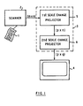
- Figure 1 shows a digital image system in which the present invention is incorporated.
- a document 1 is scanned at a high resolution (240 pels/inch) by a scanner 2.
- the resulting series of bits from the scanner is indicative of an (mxn) image array of pel sample points on the document surface selected by the scanner at the scanner resolution.
- the significance of each bit represents the state (black or white) of the corresponding pel on the document surface.
- the series of bits from scanner 2 is supplied as input to data manipulation apparatus 3 which converts the data by scale-changing processes to a series of output bits indicative of an image array (pxq) of pels suitable for display by display head 4 which operates at a lower resolution (96 pels per inch) than the scanner.
- the conversion of pel resolution by the scale-changing processes of the data manipulation apparatus is performed in two stages.
- a first scale-change projector 5 performs logical operations in accordance with a set of predominantly 1-dimensional algorithms on the series of input bits to generate a partial or intermediate result in which the number of columns in the original image array (mxn) are reduced without changing the number of rows.
- a second scale-change projector 6 performs further logical operations in accordance with the same set of algorithms on the series of intermediate output bits emerging from the scale-change projector 5 to reduce the number of rows in the intermediate image array (pxn) without changing the number of columns.
- the series of output bits emerging from the scale-change projector 6 is indicative of an image array (p xq) at the pel resolution of the display head on which it is displayed.
- the degree of scale-change in this preferred embodiment of the invention determined by the set of algorithms is the same in both dimensions of the image array. Clearly, however, the degree of scale-change in the row direction could be different from that in the column direction if desired.
- the scale-change conversion of the pels from an input row of the scanned image array (mxn) to an output row is achieved by dividing the input pels into appropriately sized fields or sub-groups. Each sub-group of pels is then replaced by one pel in the output. These sub-groups are of unequal size if the scale-change ratio is not integral. Thus, in the present example of change in resolution from 240 pels/inch at the input to 96 pels/inch at the output, the sub-groups are alternatively 2 pels and 3 pels wide giving the required average ratio of 2.5 to 1. Similarly scale-change conversion of the pels from an input column of the intermediate image array (pxn) to an output column is achieved by replacing alternate sub-groups of 2 pels and 3 pels each by one pel in the output.
- the rows of the input image are processed independently and sequentially from top to bottom.
- the sub-groups of pels in each row are processed sequentially from left to right according to the set of algorithms which determine whether the significance of the resultant output pels, each of which replaces a corresponding sub-group of pels at the input, should be black or white.
- the algorithm for scale-change conversion has been designed with the primary aim of maintaining wherever possible the existence of white-to-black and black-to-white transitions. This is equivalent to maintaining the existence of all black and white 'runs' which are the input pels between a pair of opposite polarity transitions. Thus if a 'run' completely fills or overlaps a field, or sub-group of pels, then the output pel is made the same colour as the run of pels it replaces. Conversely, the algorithm does not permit a 'run' to be represented by an output bit which replaces a sub-group of pels not included, at least in part, in the 'run'.
- a 'run' ends within a current sub-group of pels under investigation and has not yet been represented in the result, then it is said to be 'critical' since this sub- group is the last, or even the only, sub-group of pels in which the 'run' can be represented. If the current sub-group contains two or more 'critical' runs then an 'overrun' condition is said to exist. If the sub- group contains two 'non-critical' runs then a 'dilemma' is said to exist. In this case one or more runs must be dropped from the result.
- the selected phasing of the scale-change sub-group boundaries with respect to input data has an effect on the pel position in the duplicated output.
- a left-hand pel in a 3 pel sub-group occurs as 1 pel in the corresponding 5 pel subgroup and 1 pel in the preceding 5 pel sub-group.
- the algorithms used in the present invention are designed to determine the significance of output bits as though the input bits had been duplicated in this manner to extend across subgroup boundaries, although of course in practice actual duplication of bits does not take place.
- the output bits selected for all possible input bit patterns by the basic algorithm can be determined by reference to Table 1 below.
- the columns of data represent the following information:
- the above table contains only half of the possible combinations of input bits. Since the algorithm is symmetrical with respect to input data, that is it responds in the opposite way for transitions from black to white as for transitions from white to black, the other half of the table may be determined simply by inverting the binary values shown in columns B, C, D, E and F.
- any scale-changing process is to maintain reasonable legibility of the output image after projection to the lower resolution. It is desirable therefore to avoid fragmentation of entities in the input data or the introduction of spurious movements in the positions of vertical edges as a result of projection. Accordingly, when assigning output pels in the case of dilemma conditions the previous row is inspected for single transitions in the current operating window and, unless a result is forced by a potential overrun in the next sub-group, the current output pel is selected so as to maintain existing vertical edges and forty-five degree connections. If more than one transition exists in the previous line data visible in the current operating window then the output pel is selected according to the rules of the basic algorithm for dilemma conditions.
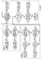
- These extensions to the basic algorithm are included in the flow chart shown in Figure 2 and add two additional routes (result 10 and result 11) to the nine already dealt with. The operation of the extension to the basic algorithm is summarised in Table 2 below.
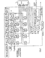
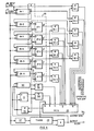
- the input image data received as a serial raster-scanned bit stream is supplied to input terminal 7 of the apparatus shown in Figure 3 for performing scale-changing in the row direction.
- the input bit stream supplied to terminal 7 is clocked each pel time by leading edges of data clock pulses (waveform (a) Figure 5) supplied to clock terminal 8 through two serially connected shift registers SR1 and SR2.
- An input line buffer 9 connected between the output of shift register SR1 and the input of shift register SR2 introduces a delay to the bit stream such that corresponding shift register stages in the two registers contain at any instant bits representing correspondingly positioned pels from successive raster-scan lines.
- the operational 'window' of input image pels defined by the algorithm is derived from shift register stages SR1.1 to SR1.5 for the current row and shift register stages SR2.0 to SR2.4 for the previous row.
- the position of the 'window' pels with respect to the image data is shown in Figure 3 with the pels numbered 1 to 6 in the current row and 0' to 4' in the preceding row.
- the corresponding shift register stages from which the 'window' is derived is shown in dotted outline 10 with the outputs from the stages similarly numbered 1 to 6 and 0' to 4' for ease of identification. It should be noted that the first pel of the sub-group of pels under investigation is always represented by the bit contained in shift register stage SR1.1.
- stage SR1.5 no stage is required for the sixth pel in the current row since the bit representing this pel is obtained from the input to stage SR1.5. It will be recalled from previous discussion of the algorithm and as seen from the 'window' layout in Figure 3 that the five pels from the previous row are displaced in the actual image one pel position to the left. The shift register SR2 is therefore displaced one stage to the right with respect to shift register SR1.
- the eleven input image bits representing the eleven pels in the 'window' are supplied together with a single bit representing the result obtained for the previous sub-group in the current row, a single bit representing the result obtained for the corresponding sub-group on the previous row, and a single bit representing the width of the current sub-group as an address word to the input of read only store (ROS) 11.
- ROS read only store
- ROS 11 contains all the single bit output words derived by the algorithm and summarised in the three tables required to replace the various input bit combinations. Interrogation of ROS 11 with the input address results in an output bit appearing at ROS output. Since the input bit pattern supplied to ROS 11 changes every pel time, a corresponding output bit appears every pel time at the ROS output. Accordingly, the output bit stream at terminal 12 is sampled under control of an output pel clock signal (waveform (d) Figure 5) alternately every 2 and 3 input pel time as required by the algorithm.
- the output pel clock signal is supplied by timing circuits 13 the operation of which will be described later with reference to Figures 4 and 5.
- the sampled output bit stream represents the input image after scale-change in the row direction.
- Each output bit from ROS 11 is supplied as input to a result latch 14 which is also clocked alternately every 2 and 3 input pel times by the output pel clock.
- the delay introduced by the clocking of the result latch means that its output represents the result bit for the previous sub-group on the current line under investigation.
- the output from the result latch 14 is supplied as part of the address to ROS 11.
- Each output bit from ROS 11 is also supplied as input to an output line buffer 15 which is also clocked by the output pel clock from timing circuits 13.
- the delay introduced by buffer 15 is such that a bit at its output represents the result bit for the sub-group of pels on the previous row corresponding in position to the current sub-group under investigation.
- the output from buffer 15 is also supplied as part of the input address to ROS 11.
- the ROS is required to store 16384 words in order to provide an output bit for each of all the possible input combinations on the fourteen input address lines.
- the black/white symmetry of the algorithm however enables the number of words to be halved.
- the tables described above contain only bit patterns in which the first pel of the investigated sub-group is a '0' since the remaining patterns in which the first pel is a '1' can be obtained by simple bit inversion.
- the first pel is a '0' then the bit pattern is represented in the tables and if it is a '1' then the inverse of the bit pattern is represented.
- This first pel is represented by the bit contained in shift register stage SR1.1 and its significance either 0 or 1 indicates whether the actual input bit pattern or its inverse is contained in the tables.
- the output from shift register stage SR1.1 is not used directly as part of the ROS address but instead is used to invert the remaining thirteen inputs and the ROS output if it is a '1' or to pass the inputs unchanged to the ROS and not invert the ROS output if it is a '0'. Accordingly, the ROS need only store the 8192 words summarised in the tables.
- the selective inversion of the thirteen address inputs is achieved automatically simply by exclusively OR-ing the first bit from the current sub-group with the bits supplied for the twelve address inputs.
- shift register SR1.1 is therefore supplied as one input to exclusive OR (XOR) circuits 16.1 to 16.5 which obtain their second inputs respectively from the outputs from shift register stages SR1.2 to SR1.5 and the input to stage SR1.5, whereby the bits representing the pels in the current line are inverted in response to the occurrence of a 1 bit in shift register stage SR1.1.
- XOR exclusive OR
- the output from SR1.1 is supplied as input to XOR circuits 17.1 to 17.5 which receive their second inputs respectively from shift register stages SR2.0 to SR2.4 whereby the bits representing the pels in the previous line are inverted in response to a 1 bit in stage SR1.1.
- stage SR1.1 is further supplied as one input to XOR circuit 18 which receives as second input the output from result latch 14 whereby the bit representing the result for the previous sub-group on the current line is selectively inverted.
- the output from stage SR1.1 is further supplied as one input to XOR circuit 19 which receives as second input the output from output line buffer 15 whereby the bit representing the result for the corresponding sub- group on the previous line is selectively inverted.
- the output from stage SR1.1 is connected as one input to XOR circuit 20 which receives the output from ROS 11 as second input, whereby the result bit supplied by the ROS is inverted wherever a 1 bit is present in shift register stage SR1.1.
- Reset lines are omitted from most of the various components forming the apparatus of Figure 3.
- each latch forming the individual stages of the shift registers SR1 and SR2, the result latch 14 and the two line buffers 9 and 15 are provided with reset inputs. It will be apparent that for the apparatus to function correctly, it is necessary to clear both line buffers so that they contain all 0's, and to reset all latches to 0 at the start of each new image input. Further, the latch forming shift register stage SR2.0 and the result latch 14 must be reset to 0 at the start of each new line scan of the image. Five extra clock pulses with a pel value of '0' must be provided at the end of each line in order to flush the shift register SR1. The reset pulses and the extra clock pulses can be simply derived using standard logical design. --
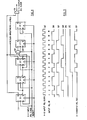
- the timing circuits 13 are seen from Figure 4 to consist of five interconnected JK flip-flops (FF) 21 and two AND gates 22 and 23.
- the J input to FF21.1 is permanently tied to an up or'1' level and the K inputs to FF21.4 and 21.5 are permanently tied to a down or '0' level.
- the input data clock pulses, waveform (a) in Figure 5 are supplied in parallel to the C inputs of all the flip-flops. Since the scale-change ratio in this embodiment is 5:2, the number of input pels per scan line should be a multiple of five.
- the example chosen to illustrate the operation of the timing circuits therefore shows 10 pels in the input line plus five extra pels (marked * ) added to the end of the line and given the value 0 in order to clear the window register SR1. All flip-flops are reset to 0 at the start of each line scan.
- the Q output from FF21.1 is shown as waveform (b) in Figure 5, the Q output from FF21.2 as waveform (c), and the Q output from FF21.3 as waveform (d). It is seen that waveform (d) is alternately at an up or '1' level for the duration of 2 input pel bit times and at a down or '0' level for 3 input pel bit times. This signal is used therefore as the sub-group width signal required as an address bit for ROS 11 in the apparatus shown in Figure 3.
- the output pel clock signal required to clock the result latch 14 and output line buffer 15 is derived from the Q output from FF21.1. Since no output pel clock signal should occur until the current row shift register SR1 is loaded, the signal must be suppressed during the first five pel bit times for each scan row. This is accomplished by the logical combination of the Q output from FF21. 1, the not Q output from FF21.2, and the not Q output from FF21.3 by AND-gate 22, the output from which is supplied as J input to FF21.4.
- the resultant Q output from FF21.4 is shown as waveform (e) in Figure 5 as an up or '1' level after pel 4 bit time.
- the Q output from FF21.4 is connected to the J input of FF21.5 so that the Q output from the latter becomes an up or'1' level one pel bit time later.
- the Q output from FF21.5 is shown as waveform (f) in Figure 5.
- the output pel clock signal shown as waveform (g) in Figure 5 is derived as a result of the logical combination of the Q outputs from FF21.1 and FF21.5 by AND-gate 23.
- the intermediate output bit stream representing the input image after scale-change in the row direction from terminal 12 ( Figure 3) is applied to input terminal 24 of the apparatus shown in Figure 6 which performs the scale-changing operation in the column direction.
- the operating 'window' in this case is vertical with respect to the input image as shown in the inset and in dotted outline 25 in the Figure 6.
- the pels for the current column are numbered 1 to 6 and for the preceding column 0' to 4'.
- line buffers 26.1 to 26.6 are required to provide the necessary row delays. Since the input data has already been processed in the row direction, each line buffer 26 is only two-fifths of the length of the original scan line.
- the six buffers are connected in series and the image data at terminal 24 is clocked through the buffers by the data clock pulses applied to clock terminal 27.
- the clock pulses are the same as the output pel clock in Figure 3 and shown as waveform (g) in Figure 5.
- the bit at the output of buffer 26.5 is six image rows behind the bit currently applied to the input of buffer 26.1.
- the first pel of the sub-groups under investigation is represented by the bit at the output of the line buffer 26.5 and the other five pels in the current column 'window' are obtained from the outputs of line buffers 26.1 to 26.4 and the input to 26.1.
- the various buffer connections have been numbered with the 'window' pel order 1 to 6 for ease of identification of the bits representing the pels in the current column.
- the bits representing the pels in the previous column of the 'window' numbered 0' to 4' are derived from the outputs of five latches 27.1 to 27.5 connected to the output of the line buffers 25.2 to 25.6.
- the line buffer 26.6 is required to provide a delay equivalent to one input row for the input to latch 27.5.
- the output lines from the five latches have been numbered with the window pel order 0' to 4' for ease of identification of the bits representing the previous column of pels.
- the significance of the bit at the output from line buffer 26.5 is used to reduce the number of output words needed to be stored by the apparatus. If this bit is a '1' then the ten bits representing the remaining 'window' pels, the result bit for the previous sub-group in the current column, the result for the correspondingly positioned sub-group in the previous column are all inverted before they are supplied as address bits to a ROS 28. If the bit from the output of buffer 26.5 is a '0' then the bits are supplied as address bits to ROS 28 without inversion. A further single bit representing the width of the current sub-group is supplied as part of the ROS input address from timing circuits 29. The operation of the timing circuits will be described later with reference to Figures 7 and 8.
- ROS 28 stores 8192 words and produces a single bit output word each pel time as a serial data output bit stream to output terminal 30.
- This bit stream contains redundant information and accordingly is sampled by an output pel clock signal (waveform (f) Figure 8), supplied by timing circuits 29, to provide bursts of one line of data alternately for every two or three lines of input data.
- This sampled output data represents the input image after scale-change in the row and column direction.
- the output bits from ROS 28 are applied to result latch 31, which is clocked by the output pel clock from timing circuits 29 to generate an output which represents the result for the corresponding sub-group of pels on the previous column.
- the ROS output is also supplied to a further line buffer 32, clocked by the output pel clock, to produce an output which represents the result for the previous sub- group of pels in the current column under investigation.
- the selective inversion of twelve of the address inputs is achieved automatically, as in the case of horizontal scale-change, simply by exclusively OR-ing the first bit from the current sub-groups with the bits supplied as the twelve ROS address bits.
- the output from line buffer 26.5 is therefore supplied as one input to XOR circuits 32.1 to 32.5 which obtain their second inputs from the input to line buffer 26.1 and the outputs from line buffers 26.1 to 26.4 respectively.
- the bits representing the pels in the current column under investigation are thus inverted on occurrence of a 1 bit at the output of buffer 26.5.
- the output from buffer 26.5 is applied as one input to XOR circuits 33.1 to 33.5 which obtain their second inputs from the outputs of latches 27.1 to 27.5 respectively.
- the bits representing the pels in the previous column are thus inverted on occurrence of a '1' bit at the output of buffer 26.5.
- the output from buffer 26.5 is further supplied as one input to XOR circuit 34 which receives the output from line buffer 32 as its second input.
- the bit representing the result for the previous sub-group of pels in the current column under investigation is inverted on occurrence of a '1' bit from buffer 26.5.
- the outputs from buffer 26.5 and result latch 31 are supplied as inputs to XOR 35 in order to invert the bit representing the result of the corresponding sub-group of pels on the previous column whenever a '1' bit occurs at the output of line buffer 26.5.
- the presence of a '1' bit at the output of buffer 25.5 is used in XOR 36 to invert the single bit result word supplied at the output of ROS 28.
- the input clock for timing circuits 29 is a pulse train at the row repetition rate.
- the input row clock pulses shown as waveform (a) Figure 8 are obtained from a column counter 37 fed with the input pel clock pulses from terminal 27 at its input.
- the timing circuits 29 are seen from Figure 7 to consist of four interconnected JK flip-flops (FF) 38 and two AND-gates 39 and 40.
- the J input to FF38.1 is permanently tied to an up or'1' level and the K input to FF38.4 is permanently tied to a down or '0' level.
- the input row clock pulses, waveform (a) in Figure 8 are supplied in parallel to the C inputs of all the flip-flops.
- the example chosen to illustrate the operation of the timing circuits has 10 scan rows of the input image with three extra rows marked * all storing zeros at the end in order to maintain operation of the apparatus until the last image scan line is cleared through the line buffers. All flip-flops and the column counter 37 ( Figure 6) are reset to zero at the start of each new image scan.
- the Q output from FF38.1 is shown as waveform (b) in Figure 5, the Q output from FF38.2 as waveform (c), and the Q output from FF38.3 as waveform (d). It is seen that waveform (d) is alternately at an up or '1' level for the duration of 2 input pel row times and at a down or '0' level for 3 input pel row times. This signal is used therefore as the sub-group width signal required as an address bit for ROS 28 ( Figure 6).
- the output pel clock signal required to clock the result latch 31 and the line buffer 32 is derived from the Q output from FF38.1. Since no output pel clock is required until the input data has reached the output of line buffer 26.5, the signal is suppressed during the first four input row times. This is accomplished by the logical combination of the Q output from FF38.1, the not Q output from FF38.2, and the not Q output from FF38.3 by AND-gate 39 the output from which is supplied as the J input to FF38.4.
- the resultant Q output from FF38.4 is shown as waveform (e) in Figure 8 as an up or '1' level after four input row times and is used as a gating signal for the Q output from FF38.1 through AND-gate 40.
- the output from AND-gate 40 is shown as waveform (f) in Figure 8 and is the output pel clock enable signal used to sample the data output signals supplied at terminal 30 from ROS 28 ( Figure 6).
- This signal sampled for one input row scan line time (two-fifths the duration of the original unprocessed scan line) alternately every two and three line times represents the original input image after scale-change has been performed in the horizontal and vertical directions.
- the embodiment described above uses a ROS to store and select the 8192 different output words.
- the fact that a large number of input addresses can be combined using 0,1 and X (don't care) states makes this table look up function particularly suited for implementation with a program logic array (PLA).
- PLA program logic array
- FIG 9. a PLA 41 is shown divided into an upper and a lower portion.
- the 39 different words listed in Table 1 are stored in the upper portion and the 60 different words listed in Table 2 and the 10 different words listed in Table 3 are stored in the lower portion.
- the 13 bit input address is applied to the PLA columns as shown and 3 output bits are generated for each resulting 'bit'.
- the outputs are arranged differently in the two portions of the PLA.
- the first output column in the top portion of the PLA contains Table 1 result bits
- the second column and third column contain all '0's.
- the first column of the lower portion of the PLA contains all 0's
- the second column contains the Table 2 and Table 3 result bits
- the third column contain all '1's.
- the outputs from the first and second output columns are fed to a funnel 42 which is controlled to pass the first or second column to its output in accordance with the value in the third column.
- a '0' in the third column enables the funnel to pass the Table 1 result in the first output column as output
- a '1' in the third column enables the funnel to pass the Table 2 or Table 3 result in the second column as output.
- the algorithm personality is in the truth tables, easy, flexible design and maintenance is allowed.
- the tables can be stored in a ROS or PLA or even a random access memory which latter would have the added advantage of allowing the tables to be changed dynamically for different scale change ratios or to suit various types of input data.
- the scale-change ratio will be the same for the two coordinate directions of the input image it can be different if required.
Description
- The invention relates to apparatus for receiving raster-scanned data as a series of input bits representing consecutive rows of an image array of picture elements (pels) at a first resolution and for converting the data into a series of output bits representing consecutive rows of an image array of pels at a second lower pel resolution.
- Information, for example alphanumerics or line drawings on a document may be digitized by a scanner into a stream of bits representing two-valued (black/white) sample points or picture elements ipels) of the scanned image in successive lines of the raster scan. The digitized information may be stored electronically in a computer, recalled from store, reconstituted and either displayed on a display terminal, printed by a printer/plotter, or transmitted over a data link to another location.
- A frequent requirement in such digital image systems is the reduction of the number of pels in an image after it has been scanned in order, for example, to reduce storage or transmission costs, to provide compatibility with a display head which has a lower pel resolution than the digitizing scanner, or to enhance the capture of fine detail. It is an objective of the present invention to provide apparatus for conversion of resolution of such image data without undue loss of legibility.
- US-A-4075663 describes apparatus for selectively changing the scale (i.e. actual size) and the pitch (i.e. the resolution) of a continuous tone image such as a photograph. The nature of the original image, which being continuous tone is represented in gray-scale, is such that no particular attention is paid to legibility as is required when dealing with stroke data. Resolution change is effected by linear interpolation of the neighbouring gray-scale values in an input matrix to provide the appropriate gray-scale values on an overlying output matrix. The spacial relationship between the two matrices defines the desired resolution change. The apparatus would be quite unsuitable for scale-change reduction of black/white images where maintenance of stroke information is important.
- US-A-4068266 describes apparatus for changing the vertical resolution of a raster scanned image. The conversion technique utilizes a stored table constructed by statistical means. No specific consideration is given to maintenance of legibility required when dealing with black/white images containing stroke information. Furthermore, the apparatus is not required to convert horizontal resolution.
- GB-2030823A describes apparatus for reducing resolution of black/white images and includes means which function to replace selected sub-groups of pels in the input image by single pels at its output. The significance of each single pel reflects the presence or absence of a pel representing part of an image object in the associated sub-group of pels. The number of pels in the selected sub-groups are determined by the degree of compression required to convert to the lower pel resolution. An important feature of the apparatus is that prior to scale-change, the input image data is modified so as to minimise merging of adjacent image objects as a result of the subsequent scale change operation. The image data modification is achieved in three stages. The scanned data is first processed by a data sensitive thinner which functions to detect narrow gaps between adjacent objects in the input image and to selectively delete edge pels from the objects in order to widen the gaps. This selectively thinned data is further thinned in order essentially to improve the appearance of the final projected image at the lower resolution. Finally the thinned image data is processed by a data sensitive merge inhibit means which moves selected pels from sub-groups in which object merging will occur as a result of scale-changing to adjacent sub-groups where merging will not occur. In all three stages, deletion or movement of a pel is inhibited if to do so would result in fragmentation of the associated image object. This patent is concerned with an alternative, although more complex method and apparatus for resolution reduction of images containing a high proportion of stroke information.
- According to the invention, apparatus for performing resolution reduction of a raster-scanned image array of picture elements (pels) by bit processing, comprising two resolution reduction means connected in series through which bits representing the image array are sequentially clocked, a first resolution reduction means being operable on receipt of a first series of bits representing said image array at the scanned resolution to supply at its output a second series of bits representing said image array in an intermediate state with the pel resolution reduced only in the row direction, and a second of said resolution reduction means being operable on receipt of said second series of bits to supply at its output a third series of bits representing said image array with the pel resolution additionally reduced in the column direction, said first resolution reduction means causing continuous replacement of sequential unique sub-groups of bits representing consecutive pels in each row of the input image occurring in a pre-determined position within a pre-defined window aligned in the row direction each with a single one of said second series of bits, and said second resolution reduction means causing continuous replacement of sequential unique sub-groups of bits representing pels occupying corresponding column positions in consecutive rows of the intermediate image occurring in a pre- determined position within a predefined window aligned in the column direction each with a single one of said third series of bits, the significance of the individual bits forming the second and third series of bits being determined in accordance with predetermined algorithms and having regard to the significance of all the bits currently located in the associated windows of which the sub-groups form a part, the scale of the resolution reduction in the row direction being determined by the selected number of bits in the sub-group associated with the window aligned in the row direction, and the scale of the resolution reduction in the column direction being determined by the selected number of bits in the sub-group associated with the window aligned in the column direction, the first resolution reduction means supplying its output bits directly to the second resolution reduction means, which second means includes only sufficient buffering to enable the column window to be filled, the arrangement being such that, under normal circumstances, the number of scan rows constituting an image array is substantially greater than the number of bit positions required for the window aligned in the column direction, whereby only a relatively small portion of the image array is in said intermediate state at any instant in time.
- In order that the invention may be fully understood, a preferred embodiment thereof will be described by way of example with reference to the accompanying drawings. In the drawings:-
- Figure 1 shows a digital image system incorporating the present invention;
- Figure 2 shows a flow chart of algorithmic rules which govern the operation of the apparatus shown in Figure 1;
- Figure 3 shows apparatus for accomplishing the horizontal scale change function;
- Figure 4 shows details of timing circuits forming part of the horizontal scale-changing apparatus of Figure 3;
- Figure 5 shows signal waveforms at various points in the apparatus of Figure 3;
- Figure 6 shows apparatus for performing scale-change of input image data in a vertical direction;
- Figure 7 shows details of timing circuits forming part of the vertical scale-changing apparatus of Figure 6;
- Figure 8 shows signal waveforms at various points in the apparatus of Figure 6; and
- Figure 9 shows a program logic array (PLA) which may be substituted for the read-only store (ROS) used in the apparatus shown in Figure 3 and the apparatus shown in Figure 6.
- Figure 1 shows a digital image system in which the present invention is incorporated. In this example, a
document 1 is scanned at a high resolution (240 pels/inch) by ascanner 2. The resulting series of bits from the scanner is indicative of an (mxn) image array of pel sample points on the document surface selected by the scanner at the scanner resolution. The significance of each bit represents the state (black or white) of the corresponding pel on the document surface. - The series of bits from
scanner 2 is supplied as input todata manipulation apparatus 3 which converts the data by scale-changing processes to a series of output bits indicative of an image array (pxq) of pels suitable for display bydisplay head 4 which operates at a lower resolution (96 pels per inch) than the scanner. The conversion of pel resolution by the scale-changing processes of the data manipulation apparatus is performed in two stages. A first scale-change projector 5 performs logical operations in accordance with a set of predominantly 1-dimensional algorithms on the series of input bits to generate a partial or intermediate result in which the number of columns in the original image array (mxn) are reduced without changing the number of rows. A second scale-change projector 6 performs further logical operations in accordance with the same set of algorithms on the series of intermediate output bits emerging from the scale-change projector 5 to reduce the number of rows in the intermediate image array (pxn) without changing the number of columns. The series of output bits emerging from the scale-change projector 6 is indicative of an image array (p xq) at the pel resolution of the display head on which it is displayed. The degree of scale-change in this preferred embodiment of the invention determined by the set of algorithms is the same in both dimensions of the image array. Clearly, however, the degree of scale-change in the row direction could be different from that in the column direction if desired. - The scale-change conversion of the pels from an input row of the scanned image array (mxn) to an output row is achieved by dividing the input pels into appropriately sized fields or sub-groups. Each sub-group of pels is then replaced by one pel in the output. These sub-groups are of unequal size if the scale-change ratio is not integral. Thus, in the present example of change in resolution from 240 pels/inch at the input to 96 pels/inch at the output, the sub-groups are alternatively 2 pels and 3 pels wide giving the required average ratio of 2.5 to 1. Similarly scale-change conversion of the pels from an input column of the intermediate image array (pxn) to an output column is achieved by replacing alternate sub-groups of 2 pels and 3 pels each by one pel in the output.
- During the operation of the first scale-
change projector 5, the rows of the input image are processed independently and sequentially from top to bottom. The sub-groups of pels in each row are processed sequentially from left to right according to the set of algorithms which determine whether the significance of the resultant output pels, each of which replaces a corresponding sub-group of pels at the input, should be black or white. - The algorithm for scale-change conversion has been designed with the primary aim of maintaining wherever possible the existence of white-to-black and black-to-white transitions. This is equivalent to maintaining the existence of all black and white 'runs' which are the input pels between a pair of opposite polarity transitions. Thus if a 'run' completely fills or overlaps a field, or sub-group of pels, then the output pel is made the same colour as the run of pels it replaces. Conversely, the algorithm does not permit a 'run' to be represented by an output bit which replaces a sub-group of pels not included, at least in part, in the 'run'. If a 'run' ends within a current sub-group of pels under investigation and has not yet been represented in the result, then it is said to be 'critical' since this sub- group is the last, or even the only, sub-group of pels in which the 'run' can be represented. If the current sub-group contains two or more 'critical' runs then an 'overrun' condition is said to exist. If the sub- group contains two 'non-critical' runs then a 'dilemma' is said to exist. In this case one or more runs must be dropped from the result.
- Where non-integral scale-change ratios, such as in this preferred embodiment, are handled by the algorithm using different sized sub-groups of pels as described, some distortion of the output image may result. This can be avoided, however, since with any scale-change ratio x:y in which x>y, the input data bits can each be considered as being duplicated y times. The resulting constrained data stream can then be divided into equally-sized sub-groups each x bits wide. By this means symmetric scale-change conversion from input to output is achieved.
- The following examples illustrate the effect of this notional duplication for the purposes of determining the significance of the output pels needed to replace 2 pel and 3 pel sub-groups. The data pels are shown on the left-hand side divided alternately into 2 pel and 3 pel sub-groups by oblique lines. Each pel (x) is duplicated and shown in 5 pel sub-groups on the right-hand side, thus:

- The selected phasing of the scale-change sub-group boundaries with respect to input data has an effect on the pel position in the duplicated output. Thus, a left-hand pel in a 3 pel sub-group occurs as 1 pel in the corresponding 5 pel subgroup and 1 pel in the preceding 5 pel sub-group. The algorithms used in the present invention are designed to determine the significance of output bits as though the input bits had been duplicated in this manner to extend across subgroup boundaries, although of course in practice actual duplication of bits does not take place.
- The basic algorithmic rules selected for the operation of the invention in accordance with this embodiment may be summarized as follows:
- 1. input sub-group containing only one run is replaced by a single output bit of the same significance as the bits forming the run;
- 2. input sub-group containing two or three runs only one of which is critical is replaced by a single output bit of the same significance as the bits forming the critical run;
- 3. input sub-group containing two non-critical runs (dilemma condition) is generally replaced by a single output bit of the same significance as the majority of bits in the input sub-group. An exception to this is when the selection of a particular significance would cause an 'overrun' condition in the next sub-group which could otherwise be avoided. In this case an output bit of the opposite significance is selected to replace the input sub-group. A second exception may occur when the second run has a total length of one pel only. In this case the output bit has the significance of the second run.
- 4. input sub-group containing two or more critical runs (overrun condition) is replaced by an output bit of the same significance as that previously selected for the output bit for the corresponding sub-group in the previous line.
- In order to assist in the understanding of the basic algorithm, the decisions of the significance of the output bits selected for all possible combinations of input bits are summarized in a flow chart shown as Figure 2. There are nine possible different routes associated with the basic algorithm so far described and the corresponding results are labelled
result 1 to result 9 on the chart for ease of reference. - The output bits selected for all possible input bit patterns by the basic algorithm can be determined by reference to Table 1 below. The columns of data represent the following information:
- column A represents the width of the current sub-group under investigation (0=2 pel sub-group, 1=3 pel sub-group);
- column B contains the binary values of the next six pels in the row starting with the first pel in the current sub-group (0=white pel, 1 =black pel, X=white or black pel);
- column C contains the significance of the output pel derived for the previous sub-group of input pels in that row (0=white pel, 1 =black pel, X=white or black pel);
- column D contains the binary values of five input pels from the previous scan row starting one pel position to the left of the corresponding current sub-group in that row (0=white pel, 1=black pel, X=white or black pel);
Note: This information is not required by the basic algorithm but is included in Table 1 in order to be consistent with other tables to be described later. - column E contains the significance of the output pel derived for the corresponding sub-group of input pels in the previous row (0=white pel, 1=black pel, X=white or black pel);
- column F contains the significance of the output pel derived for the current sub-group of input pels under investigation (0=white pel, 1 =black pel);
- column G contains remarks describing the nature of the bit information in the sub-group under investigation in the terms defined above, and in the case of 'dilemma' and 'overrun' conditions, the reason for the selection of the significance of the corresponding output bit; and
- column H contains the corresponding result box number from the flow chart shown in Figure 2 from which the algorithmic decision route can be derived.

- It will be observed that the above table contains only half of the possible combinations of input bits. Since the algorithm is symmetrical with respect to input data, that is it responds in the opposite way for transitions from black to white as for transitions from white to black, the other half of the table may be determined simply by inverting the binary values shown in columns B, C, D, E and F.
- The primary objective of any scale-changing process is to maintain reasonable legibility of the output image after projection to the lower resolution. It is desirable therefore to avoid fragmentation of entities in the input data or the introduction of spurious movements in the positions of vertical edges as a result of projection. Accordingly, when assigning output pels in the case of dilemma conditions the previous row is inspected for single transitions in the current operating window and, unless a result is forced by a potential overrun in the next sub-group, the current output pel is selected so as to maintain existing vertical edges and forty-five degree connections. If more than one transition exists in the previous line data visible in the current operating window then the output pel is selected according to the rules of the basic algorithm for dilemma conditions. These extensions to the basic algorithm are included in the flow chart shown in Figure 2 and add two additional routes (
result 10 and result 11) to the nine already dealt with. The operation of the extension to the basic algorithm is summarised in Table 2 below.
- All possible input bit patterns which lead to the maintenance of a vertical edge (result 10) or a forty-five degree connection (result 11) following detection of a dilemma condition may be determined from the above table. The significance of the information in the various columns of the table is the same as for Table 1. Again only half of the possible input conditions are shown in the table as before, the other half may be determined simply by inverting the binary values shown in columns B, C, D, E and F.
- Although the basic algorithm produces acceptable results for the majority of input bit patterns, there are some patterns which lead to distortion of the output image if the basic rules are followed. For example, consider the input bit pattern 00/100/0 following a previous sub-group result bit of
significance 0. From Table 1 it is seen that the current 2 pel sub-group under consideration is set to a pel ofsignificance 1 for any valued bit combination in the previous scan row. Generally, this is an acceptable decision. However, consideration of a previous line bit pattern X/01/1X in which the corresponding 2 pel sub-group 01 was replaced by a result pel ofsignificance 0 has the effect of changing the slope of the edge in the input image from downwards left to right to downwards right to left in the output image. The decision in this particular example derived from the general algorithm is clearly undesirable and a further modification to the basic algorithm is made to overcome the problem by forcing the result pel to copy the result pel for the corresponding sub-groups in the previous scan row. The modifications are included in the flow chart shown in Figure 2 as two further routes (result 12 and result 13). All the exceptions to the basic algorithm which lead to edge direction changes as described above are summarised in Table 3 below.
- The significance of the information in the various columns of the table is the same as for Table 1 and 2. Again only half of the possible input conditions are shown in the table and as before, the other half may be determined simply by inverting the binary values shown in columns B, C, D, E and F.
- This completes the description of the algorithm and its modifications used in this preferred embodiment to determine the significance of result pels in the projected output image at the lower pel resolution. The preferred arrangement for the implementation of the scale-change algorithm will now be described.
- The input image data received as a serial raster-scanned bit stream is supplied to input
terminal 7 of the apparatus shown in Figure 3 for performing scale-changing in the row direction. The input bit stream supplied toterminal 7 is clocked each pel time by leading edges of data clock pulses (waveform (a) Figure 5) supplied toclock terminal 8 through two serially connected shift registers SR1 and SR2. Aninput line buffer 9 connected between the output of shift register SR1 and the input of shift register SR2 introduces a delay to the bit stream such that corresponding shift register stages in the two registers contain at any instant bits representing correspondingly positioned pels from successive raster-scan lines. The operational 'window' of input image pels defined by the algorithm is derived from shift register stages SR1.1 to SR1.5 for the current row and shift register stages SR2.0 to SR2.4 for the previous row. The position of the 'window' pels with respect to the image data is shown in Figure 3 with the pels numbered 1 to 6 in the current row and 0' to 4' in the preceding row. The corresponding shift register stages from which the 'window' is derived is shown in dottedoutline 10 with the outputs from the stages similarly numbered 1 to 6 and 0' to 4' for ease of identification. It should be noted that the first pel of the sub-group of pels under investigation is always represented by the bit contained in shift register stage SR1.1. Further no stage is required for the sixth pel in the current row since the bit representing this pel is obtained from the input to stage SR1.5. It will be recalled from previous discussion of the algorithm and as seen from the 'window' layout in Figure 3 that the five pels from the previous row are displaced in the actual image one pel position to the left. The shift register SR2 is therefore displaced one stage to the right with respect to shift register SR1. - In the simplest arrangement for implementing the algorithm, the eleven input image bits representing the eleven pels in the 'window' are supplied together with a single bit representing the result obtained for the previous sub-group in the current row, a single bit representing the result obtained for the corresponding sub-group on the previous row, and a single bit representing the width of the current sub-group as an address word to the input of read only store (ROS) 11.
-
ROS 11 contains all the single bit output words derived by the algorithm and summarised in the three tables required to replace the various input bit combinations. Interrogation ofROS 11 with the input address results in an output bit appearing at ROS output. Since the input bit pattern supplied toROS 11 changes every pel time, a corresponding output bit appears every pel time at the ROS output. Accordingly, the output bit stream atterminal 12 is sampled under control of an output pel clock signal (waveform (d) Figure 5) alternately every 2 and 3 input pel time as required by the algorithm. The output pel clock signal is supplied by timingcircuits 13 the operation of which will be described later with reference to Figures 4 and 5. The sampled output bit stream represents the input image after scale-change in the row direction. - Each output bit from
ROS 11 is supplied as input to aresult latch 14 which is also clocked alternately every 2 and 3 input pel times by the output pel clock. The delay introduced by the clocking of the result latch means that its output represents the result bit for the previous sub-group on the current line under investigation. The output from theresult latch 14 is supplied as part of the address toROS 11. - Each output bit from
ROS 11 is also supplied as input to anoutput line buffer 15 which is also clocked by the output pel clock from timingcircuits 13. The delay introduced bybuffer 15 is such that a bit at its output represents the result bit for the sub-group of pels on the previous row corresponding in position to the current sub-group under investigation. The output frombuffer 15 is also supplied as part of the input address toROS 11. - With this simple arrangement, the ROS is required to store 16384 words in order to provide an output bit for each of all the possible input combinations on the fourteen input address lines. The black/white symmetry of the algorithm however enables the number of words to be halved. It will be recalled that the tables described above contain only bit patterns in which the first pel of the investigated sub-group is a '0' since the remaining patterns in which the first pel is a '1' can be obtained by simple bit inversion. Thus if the first pel is a '0' then the bit pattern is represented in the tables and if it is a '1' then the inverse of the bit pattern is represented. This first pel is represented by the bit contained in shift register stage SR1.1 and its significance either 0 or 1 indicates whether the actual input bit pattern or its inverse is contained in the tables.
- In the preferred form of apparatus shown in Figure 3, the output from shift register stage SR1.1 is not used directly as part of the ROS address but instead is used to invert the remaining thirteen inputs and the ROS output if it is a '1' or to pass the inputs unchanged to the ROS and not invert the ROS output if it is a '0'. Accordingly, the ROS need only store the 8192 words summarised in the tables. The selective inversion of the thirteen address inputs is achieved automatically simply by exclusively OR-ing the first bit from the current sub-group with the bits supplied for the twelve address inputs. The output from shift register SR1.1 is therefore supplied as one input to exclusive OR (XOR) circuits 16.1 to 16.5 which obtain their second inputs respectively from the outputs from shift register stages SR1.2 to SR1.5 and the input to stage SR1.5, whereby the bits representing the pels in the current line are inverted in response to the occurrence of a 1 bit in shift register stage SR1.1. Similarly, the output from SR1.1 is supplied as input to XOR circuits 17.1 to 17.5 which receive their second inputs respectively from shift register stages SR2.0 to SR2.4 whereby the bits representing the pels in the previous line are inverted in response to a 1 bit in stage SR1.1. The output from stage SR1.1 is further supplied as one input to
XOR circuit 18 which receives as second input the output fromresult latch 14 whereby the bit representing the result for the previous sub-group on the current line is selectively inverted. The output from stage SR1.1 is further supplied as one input toXOR circuit 19 which receives as second input the output fromoutput line buffer 15 whereby the bit representing the result for the corresponding sub- group on the previous line is selectively inverted. Finally, the output from stage SR1.1 is connected as one input toXOR circuit 20 which receives the output fromROS 11 as second input, whereby the result bit supplied by the ROS is inverted wherever a 1 bit is present in shift register stage SR1.1. - Reset lines are omitted from most of the various components forming the apparatus of Figure 3. In practice, each latch forming the individual stages of the shift registers SR1 and SR2, the
result latch 14 and the twoline buffers result latch 14 must be reset to 0 at the start of each new line scan of the image. Five extra clock pulses with a pel value of '0' must be provided at the end of each line in order to flush the shift register SR1. The reset pulses and the extra clock pulses can be simply derived using standard logical design. -- - The timing
circuits 13 are seen from Figure 4 to consist of five interconnected JK flip-flops (FF) 21 and two ANDgates value 0 in order to clear the window register SR1. All flip-flops are reset to 0 at the start of each line scan. - The Q output from FF21.1 is shown as waveform (b) in Figure 5, the Q output from FF21.2 as waveform (c), and the Q output from FF21.3 as waveform (d). It is seen that waveform (d) is alternately at an up or '1' level for the duration of 2 input pel bit times and at a down or '0' level for 3 input pel bit times. This signal is used therefore as the sub-group width signal required as an address bit for
ROS 11 in the apparatus shown in Figure 3. - The output pel clock signal required to clock the
result latch 14 andoutput line buffer 15 is derived from the Q output from FF21.1. Since no output pel clock signal should occur until the current row shift register SR1 is loaded, the signal must be suppressed during the first five pel bit times for each scan row. This is accomplished by the logical combination of the Q output from FF21. 1, the not Q output from FF21.2, and the not Q output from FF21.3 byAND-gate 22, the output from which is supplied as J input to FF21.4. The resultant Q output from FF21.4 is shown as waveform (e) in Figure 5 as an up or '1' level afterpel 4 bit time. The Q output from FF21.4 is connected to the J input of FF21.5 so that the Q output from the latter becomes an up or'1' level one pel bit time later. The Q output from FF21.5 is shown as waveform (f) in Figure 5. The output pel clock signal shown as waveform (g) in Figure 5 is derived as a result of the logical combination of the Q outputs from FF21.1 and FF21.5 byAND-gate 23. - The intermediate output bit stream representing the input image after scale-change in the row direction from terminal 12 (Figure 3) is applied to input
terminal 24 of the apparatus shown in Figure 6 which performs the scale-changing operation in the column direction. The operating 'window' in this case is vertical with respect to the input image as shown in the inset and indotted outline 25 in the Figure 6. The pels for the current column are numbered 1 to 6 and for the preceding column 0' to 4'. In order to sample the bits passing through the 'window' six line buffers 26.1 to 26.6 are required to provide the necessary row delays. Since the input data has already been processed in the row direction, each line buffer 26 is only two-fifths of the length of the original scan line. - The six buffers are connected in series and the image data at
terminal 24 is clocked through the buffers by the data clock pulses applied toclock terminal 27. The clock pulses are the same as the output pel clock in Figure 3 and shown as waveform (g) in Figure 5. During operation with the buffers full, the bit at the output of buffer 26.5 is six image rows behind the bit currently applied to the input of buffer 26.1. - Accordingly, the first pel of the sub-groups under investigation is represented by the bit at the output of the line buffer 26.5 and the other five pels in the current column 'window' are obtained from the outputs of line buffers 26.1 to 26.4 and the input to 26.1. The various buffer connections have been numbered with the 'window'
pel order 1 to 6 for ease of identification of the bits representing the pels in the current column. The bits representing the pels in the previous column of the 'window' numbered 0' to 4' are derived from the outputs of five latches 27.1 to 27.5 connected to the output of the line buffers 25.2 to 25.6. The line buffer 26.6 is required to provide a delay equivalent to one input row for the input to latch 27.5. The output lines from the five latches have been numbered with the window pel order 0' to 4' for ease of identification of the bits representing the previous column of pels. - As with the scale-change apparatus for the row direction, the significance of the bit at the output from line buffer 26.5, that is the bit representing the first pel in the sub-group under investigation, is used to reduce the number of output words needed to be stored by the apparatus. If this bit is a '1' then the ten bits representing the remaining 'window' pels, the result bit for the previous sub-group in the current column, the result for the correspondingly positioned sub-group in the previous column are all inverted before they are supplied as address bits to a
ROS 28. If the bit from the output of buffer 26.5 is a '0' then the bits are supplied as address bits toROS 28 without inversion. A further single bit representing the width of the current sub-group is supplied as part of the ROS input address from timingcircuits 29. The operation of the timing circuits will be described later with reference to Figures 7 and 8. -
ROS 28 stores 8192 words and produces a single bit output word each pel time as a serial data output bit stream to output terminal 30. This bit stream contains redundant information and accordingly is sampled by an output pel clock signal (waveform (f) Figure 8), supplied by timingcircuits 29, to provide bursts of one line of data alternately for every two or three lines of input data. This sampled output data represents the input image after scale-change in the row and column direction. - The output bits from
ROS 28 are applied to resultlatch 31, which is clocked by the output pel clock from timingcircuits 29 to generate an output which represents the result for the corresponding sub-group of pels on the previous column. The ROS output is also supplied to afurther line buffer 32, clocked by the output pel clock, to produce an output which represents the result for the previous sub- group of pels in the current column under investigation. The selective inversion of twelve of the address inputs is achieved automatically, as in the case of horizontal scale-change, simply by exclusively OR-ing the first bit from the current sub-groups with the bits supplied as the twelve ROS address bits. The output from line buffer 26.5 is therefore supplied as one input to XOR circuits 32.1 to 32.5 which obtain their second inputs from the input to line buffer 26.1 and the outputs from line buffers 26.1 to 26.4 respectively. The bits representing the pels in the current column under investigation are thus inverted on occurrence of a 1 bit at the output of buffer 26.5. The output from buffer 26.5 is applied as one input to XOR circuits 33.1 to 33.5 which obtain their second inputs from the outputs of latches 27.1 to 27.5 respectively. The bits representing the pels in the previous column are thus inverted on occurrence of a '1' bit at the output of buffer 26.5. The output from buffer 26.5 is further supplied as one input toXOR circuit 34 which receives the output fromline buffer 32 as its second input. The bit representing the result for the previous sub-group of pels in the current column under investigation is inverted on occurrence of a '1' bit from buffer 26.5. Likewise, the outputs from buffer 26.5 and resultlatch 31 are supplied as inputs toXOR 35 in order to invert the bit representing the result of the corresponding sub-group of pels on the previous column whenever a '1' bit occurs at the output of line buffer 26.5. Finally, the presence of a '1' bit at the output of buffer 25.5 is used inXOR 36 to invert the single bit result word supplied at the output ofROS 28. - It will be apparent that in order for the column scale-changing apparatus described above to function correctly it is necessary to clear the two first line buffers 26.1 and 26.2 so that they contain all zeros, reset the
output latch 31 to zero, and clear theline buffer 32 before the image data is supplied to input terminal 24. Further, the previous column latches 27.1 to 27.5 must be reset to zero for the first column in each image row. The reset lines for this operation are not shown in Figure 6. These extra rows with a pel value of '0' must be provided at the end of each image in order to flush out the line buffers 26.1 to 26.3. The reset pulses and the extra clock pulses can be simply derived using standard logical design. The timingcircuits 29 are similar to timing circuits 13 (Figure 3) as will be seen. However since the 'window' operates on pels in columns, valid output data is only available at output terminal 30 alternately every two and three input row times. Accordingly, the input clock for timingcircuits 29 is a pulse train at the row repetition rate. The input row clock pulses shown as waveform (a) Figure 8 are obtained from acolumn counter 37 fed with the input pel clock pulses from terminal 27 at its input. - The timing
circuits 29 are seen from Figure 7 to consist of four interconnected JK flip-flops (FF) 38 and two AND-gates - The Q output from FF38.1 is shown as waveform (b) in Figure 5, the Q output from FF38.2 as waveform (c), and the Q output from FF38.3 as waveform (d). It is seen that waveform (d) is alternately at an up or '1' level for the duration of 2 input pel row times and at a down or '0' level for 3 input pel row times. This signal is used therefore as the sub-group width signal required as an address bit for ROS 28 (Figure 6).
- The output pel clock signal required to clock the
result latch 31 and theline buffer 32 is derived from the Q output from FF38.1. Since no output pel clock is required until the input data has reached the output of line buffer 26.5, the signal is suppressed during the first four input row times. This is accomplished by the logical combination of the Q output from FF38.1, the not Q output from FF38.2, and the not Q output from FF38.3 byAND-gate 39 the output from which is supplied as the J input to FF38.4. The resultant Q output from FF38.4 is shown as waveform (e) in Figure 8 as an up or '1' level after four input row times and is used as a gating signal for the Q output from FF38.1 throughAND-gate 40. The output fromAND-gate 40 is shown as waveform (f) in Figure 8 and is the output pel clock enable signal used to sample the data output signals supplied at terminal 30 from ROS 28 (Figure 6). This signal, sampled for one input row scan line time (two-fifths the duration of the original unprocessed scan line) alternately every two and three line times represents the original input image after scale-change has been performed in the horizontal and vertical directions. - The embodiment described above uses a ROS to store and select the 8192 different output words. The fact that a large number of input addresses can be combined using 0,1 and X (don't care) states makes this table look up function particularly suited for implementation with a program logic array (PLA). Such an implementation is shown in Figure 9. Here a
PLA 41 is shown divided into an upper and a lower portion. The 39 different words listed in Table 1 are stored in the upper portion and the 60 different words listed in Table 2 and the 10 different words listed in Table 3 are stored in the lower portion. The 13 bit input address is applied to the PLA columns as shown and 3 output bits are generated for each resulting 'bit'. The outputs are arranged differently in the two portions of the PLA. Thus, the first output column in the top portion of the PLA contains Table 1 result bits, the second column and third column contain all '0's. In contrast the first column of the lower portion of the PLA contains all 0's, the second column contains the Table 2 and Table 3 result bits, and the third column contain all '1's. The outputs from the first and second output columns are fed to afunnel 42 which is controlled to pass the first or second column to its output in accordance with the value in the third column. Thus a '0' in the third column enables the funnel to pass the Table 1 result in the first output column as output whereas a '1' in the third column enables the funnel to pass the Table 2 or Table 3 result in the second column as output. - Since the algorithm personality is in the truth tables, easy, flexible design and maintenance is allowed. The tables can be stored in a ROS or PLA or even a random access memory which latter would have the added advantage of allowing the tables to be changed dynamically for different scale change ratios or to suit various types of input data. Finally, although in general the scale-change ratio will be the same for the two coordinate directions of the input image it can be different if required.
Claims (13)
Applications Claiming Priority (2)
| Application Number | Priority Date | Filing Date | Title |
|---|---|---|---|
| GB7848628A GB2038142B (en) | 1978-12-15 | 1978-12-15 | Image data compression |
| GB4862878 | 1978-12-15 |
Publications (2)
| Publication Number | Publication Date |
|---|---|
| EP0012173A1 EP0012173A1 (en) | 1980-06-25 |
| EP0012173B1 true EP0012173B1 (en) | 1983-01-26 |
Family
ID=10501741
Family Applications (1)
| Application Number | Title | Priority Date | Filing Date |
|---|---|---|---|
| EP79103924A Expired EP0012173B1 (en) | 1978-12-15 | 1979-10-12 | Apparatus for picture processing with resolution conversion |
Country Status (7)
| Country | Link |
|---|---|
| US (1) | US4280143A (en) |
| EP (1) | EP0012173B1 (en) |
| JP (1) | JPS5583952A (en) |
| AU (1) | AU532191B2 (en) |
| CA (1) | CA1122710A (en) |
| DE (1) | DE2964630D1 (en) |
| GB (1) | GB2038142B (en) |
Families Citing this family (42)
| Publication number | Priority date | Publication date | Assignee | Title |
|---|---|---|---|---|
| US4366508A (en) * | 1980-03-07 | 1982-12-28 | Xerox Corporation | Image magnification and demagnification system |
| US4342052A (en) * | 1980-06-16 | 1982-07-27 | International Business Machines Corporation | Multiple image facsimile |
| DE3036711C2 (en) * | 1980-09-29 | 1985-08-01 | Siemens AG, 1000 Berlin und 8000 München | Process for reducing graphic patterns |
| JPS57193834A (en) * | 1981-05-25 | 1982-11-29 | Yokogawa Hokushin Electric Corp | Document processing system |
| US4520399A (en) * | 1982-01-29 | 1985-05-28 | Tokyo Shibaura Kenki Kabushiki Kaisha | Picture information display device |
| US4587621A (en) * | 1982-03-08 | 1986-05-06 | The Mead Corporation | Device for electrical variable magnification of document image |
| US4532602A (en) * | 1982-03-08 | 1985-07-30 | The Mead Corporation | Device for electrical variable magnification of document image |
| US4610026A (en) * | 1982-04-30 | 1986-09-02 | Hitachi, Ltd. | Method of and apparatus for enlarging/reducing two-dimensional images |
| DE3229777C2 (en) * | 1982-08-10 | 1984-06-07 | Siemens AG, 1000 Berlin und 8000 München | Circuit arrangement for adapting two image processing systems with different resolutions |
| US5276533A (en) * | 1982-10-08 | 1994-01-04 | Canon Kabushiki Kaisha | Image processing system |
| DE3382831T2 (en) * | 1982-10-08 | 2000-10-12 | Canon Kk | Image processing device |
| US4523330A (en) * | 1982-12-23 | 1985-06-11 | Ncr Canada Ltd - Ncr Canada Ltee | Banking system and method |
| JPS6055767A (en) * | 1983-08-25 | 1985-04-01 | インタ−ナショナル ビジネス マシ−ンズ コ−ポレ−ション | Method of converting bit number of image |
| DE3486126T2 (en) * | 1983-09-29 | 1993-11-04 | Matsushita Electric Ind Co Ltd | EXPANSION AND / OR DRAWING METHOD AND DEVICE FOR IMAGE DATA. |
| US4569081A (en) * | 1983-12-30 | 1986-02-04 | International Business Machines Corporation | Method for expansion of a digital image |
| JPS60146369A (en) * | 1983-12-30 | 1985-08-02 | インタ−ナショナル ビジネス マシ−ンズ コ−ポレ−ション | Image reduction method |
| US4712140A (en) * | 1983-12-30 | 1987-12-08 | International Business Machines Corporation | Image reduction method |
| JPS60208164A (en) * | 1984-03-30 | 1985-10-19 | Canon Inc | Recorder |
| US4656664A (en) * | 1984-10-24 | 1987-04-07 | International Business Machines Corporation | Method for reducing a binary image |
| US4578689A (en) * | 1984-11-26 | 1986-03-25 | Data Recording Systems, Inc. | Dual mode laser printer |
| JP2583043B2 (en) * | 1984-12-06 | 1997-02-19 | 大日本スクリ−ン製造株式会社 | Image data compression device |
| US4772955A (en) * | 1985-01-31 | 1988-09-20 | Canon Kabushiki Kaisha | Data communication apparatus |
| US4644409A (en) * | 1985-02-26 | 1987-02-17 | Advanced Micro Devices, Inc. | Document resolution-adaption method and apparatus |
| US4712141A (en) * | 1985-03-30 | 1987-12-08 | Dainippon Screen Mfg. Co., Ltd. | Method and apparatus for interpolating image signals |
| DE3527725A1 (en) * | 1985-08-02 | 1987-02-12 | Licentia Gmbh | METHOD FOR AUTOMATICALLY ADAPTING DIFFERENTLY LARGE OPTO-ELECTRONICALLY TO BE SCANNED FORMATS TO A SPECIFIED IMAGE FORMAT FORM AND ARRANGEMENT FOR IMPLEMENTING THE METHOD |
| GB8528895D0 (en) * | 1985-11-23 | 1986-01-02 | Int Computers Ltd | Processing digitised images |
| JPS62297977A (en) * | 1986-06-17 | 1987-12-25 | Toshiba Corp | Image information storing and retrieving device |
| JPS63236472A (en) * | 1987-03-25 | 1988-10-03 | Fujitsu Ltd | Picture information encoding processing system |
| JP2998960B2 (en) * | 1988-08-26 | 2000-01-17 | キヤノン株式会社 | Communication method |
| US4970604A (en) * | 1989-04-14 | 1990-11-13 | Coueignoux Philippe J | Screen display enhancing system |
| US5025325A (en) * | 1989-10-13 | 1991-06-18 | Hewlett-Packard Company | Graphics scaling method for high resolution printers |
| US5068905A (en) * | 1989-12-28 | 1991-11-26 | Eastman Kodak Company | Scaler gate array for scaling image data |
| US5097518A (en) * | 1990-02-27 | 1992-03-17 | Eastman Kodak Company | Technique for performing digital image scaling by logically combining or replicating pixels in blocks of differing groupsizes |
| US5335295A (en) * | 1991-05-08 | 1994-08-02 | International Business Machines Corporation | System and method for scaling a digital image |
| JPH0563873A (en) * | 1991-09-04 | 1993-03-12 | Fukuda Denshi Co Ltd | Display device |
| EP0671700A3 (en) * | 1994-03-07 | 1996-11-20 | Lexmark Int Inc | Bit-map adjustment method which preserves resolution. |
| JP3634410B2 (en) * | 1994-10-18 | 2005-03-30 | キヤノン株式会社 | Image processing system, image processing apparatus and method |
| JPH1075347A (en) * | 1996-06-24 | 1998-03-17 | Nikon Corp | Film image reader and storage medium storing control procedure to the film image reader |
| JP2004264920A (en) * | 2003-02-26 | 2004-09-24 | Sony Corp | Device and method for creating thumbnail image and improving quality of resized image |
| BRPI0514776A (en) * | 2004-08-31 | 2008-06-24 | France Telecom | visibility data compression process and system, visibility data code decompression process, decoder, visibility data processing station, visibility data representative signal, and, computer program |
| JP2007067917A (en) * | 2005-08-31 | 2007-03-15 | Matsushita Electric Ind Co Ltd | Image data processing apparatus |
| US11710015B2 (en) * | 2020-08-05 | 2023-07-25 | Global Graphics Software Limited | Systems and methods for planning and producing images using plants |
Citations (4)
| Publication number | Priority date | Publication date | Assignee | Title |
|---|---|---|---|---|
| US4032977A (en) * | 1976-06-03 | 1977-06-28 | Xerox Corporation | Gray scale interpolation technique |
| US4068266A (en) * | 1976-06-03 | 1978-01-10 | Xerox Corporation | Statistical resolution conversion technique |
| US4075663A (en) * | 1975-03-19 | 1978-02-21 | Dr. -Ing. Rudolf Hell Gmbh | Method for the rastered reproduction of half-tone pictures providing changes in the individual picture elements during transfer from an original to a reproduction |
| GB2030823A (en) * | 1978-10-02 | 1980-04-10 | Ibm | Image data manipulation apparatus |
Family Cites Families (5)
| Publication number | Priority date | Publication date | Assignee | Title |
|---|---|---|---|---|
| US3976982A (en) * | 1975-05-12 | 1976-08-24 | International Business Machines Corporation | Apparatus for image manipulation |
| DE2625973C3 (en) * | 1976-06-10 | 1981-12-24 | Philips Patentverwaltung Gmbh, 2000 Hamburg | Method and arrangement for the redundancy-reducing transformation of images |
| US4124871A (en) * | 1977-08-31 | 1978-11-07 | International Business Machines Corporation | Image data resolution change apparatus and process utilizing boundary compression coding of objects |
| US4210936A (en) * | 1977-12-27 | 1980-07-01 | Pitney Bowes Inc. | Method and apparatus for reproducing an original gray scale image |
| US4215414A (en) * | 1978-03-07 | 1980-07-29 | Hughes Aircraft Company | Pseudogaussian video output processing for digital display |
-
1978
- 1978-12-15 GB GB7848628A patent/GB2038142B/en not_active Expired
-
1979
- 1979-09-28 US US06/079,779 patent/US4280143A/en not_active Expired - Lifetime
- 1979-10-12 DE DE7979103924T patent/DE2964630D1/en not_active Expired
- 1979-10-12 EP EP79103924A patent/EP0012173B1/en not_active Expired
- 1979-11-09 JP JP14450679A patent/JPS5583952A/en active Granted
- 1979-12-05 AU AU53489/79A patent/AU532191B2/en not_active Ceased
- 1979-12-14 CA CA341,987A patent/CA1122710A/en not_active Expired
Patent Citations (4)
| Publication number | Priority date | Publication date | Assignee | Title |
|---|---|---|---|---|
| US4075663A (en) * | 1975-03-19 | 1978-02-21 | Dr. -Ing. Rudolf Hell Gmbh | Method for the rastered reproduction of half-tone pictures providing changes in the individual picture elements during transfer from an original to a reproduction |
| US4032977A (en) * | 1976-06-03 | 1977-06-28 | Xerox Corporation | Gray scale interpolation technique |
| US4068266A (en) * | 1976-06-03 | 1978-01-10 | Xerox Corporation | Statistical resolution conversion technique |
| GB2030823A (en) * | 1978-10-02 | 1980-04-10 | Ibm | Image data manipulation apparatus |
Also Published As
| Publication number | Publication date |
|---|---|
| GB2038142B (en) | 1982-11-24 |
| GB2038142A (en) | 1980-07-16 |
| AU5348979A (en) | 1980-06-19 |
| US4280143A (en) | 1981-07-21 |
| AU532191B2 (en) | 1983-09-22 |
| EP0012173A1 (en) | 1980-06-25 |
| CA1122710A (en) | 1982-04-27 |
| JPH0258831B2 (en) | 1990-12-10 |
| DE2964630D1 (en) | 1983-03-03 |
| JPS5583952A (en) | 1980-06-24 |
Similar Documents
| Publication | Publication Date | Title |
|---|---|---|
| EP0012173B1 (en) | Apparatus for picture processing with resolution conversion | |
| US4079367A (en) | Apparatus for forming a character out of a pattern of separate display picture elements | |
| US4686580A (en) | Method and apparatus for changing image size | |
| US4290084A (en) | Method and means for preserving original continuity/discontinuity among same colored pel clusters upon array compression | |
| US5034806A (en) | Image processing apparatus and method | |
| US4962542A (en) | Method for reducing artifacts in error diffused images | |
| JPS6224297A (en) | Controller for graphic pattern | |
| JPS6110360A (en) | Picture processing device | |
| US5068914A (en) | Apparatus for reducing artifacts in error diffused images | |
| JPS6049391A (en) | Raster scan display system | |
| US4231095A (en) | Remote reproduction of images | |
| JPH03189878A (en) | Edit control system for image processing device | |
| JPH01183960A (en) | Picture information recording device | |
| US5117468A (en) | Image processing system capable of carrying out local processing for image at high speed | |
| US4760466A (en) | Image scanner controller | |
| JPH04294166A (en) | Image processor | |
| US4809343A (en) | Maximum/minimum value conversion circuit for image processing | |
| US5606656A (en) | Image data processing unit for forming a plurality of identical images in a single output image area | |
| JPS595901B2 (en) | character generator | |
| JPS5930163A (en) | Numbering circuit | |
| JP2839578B2 (en) | Image data input processing device | |
| SU951372A1 (en) | Device for reproducing half-tone images on cathode-ray tube screen | |
| JPH0420071A (en) | Picture processor | |
| JPS60236362A (en) | Picture information processing method | |
| JPS61199958A (en) | Ink jet recording device |
Legal Events
| Date | Code | Title | Description |
|---|---|---|---|
| PUAI | Public reference made under article 153(3) epc to a published international application that has entered the european phase |
Free format text: ORIGINAL CODE: 0009012 |
|
| AK | Designated contracting states |
Designated state(s): DE FR GB IT |
|
| 17P | Request for examination filed | ||
| GRAA | (expected) grant |
Free format text: ORIGINAL CODE: 0009210 |
|
| AK | Designated contracting states |
Designated state(s): DE FR GB IT |
|
| PG25 | Lapsed in a contracting state [announced via postgrant information from national office to epo] |
Ref country code: IT Free format text: LAPSE BECAUSE OF FAILURE TO SUBMIT A TRANSLATION OF THE DESCRIPTION OR TO PAY THE FEE WITHIN THE PRESCRIBED TIME-LIMIT;WARNING: LAPSES OF ITALIAN PATENTS WITH EFFECTIVE DATE BEFORE 2007 MAY HAVE OCCURRED AT ANY TIME BEFORE 2007. THE CORRECT EFFECTIVE DATE MAY BE DIFFERENT FROM THE ONE RECORDED. Effective date: 19830126 |
|
| REF | Corresponds to: |
Ref document number: 2964630 Country of ref document: DE Date of ref document: 19830303 |
|
| ET | Fr: translation filed | ||
| PGFP | Annual fee paid to national office [announced via postgrant information from national office to epo] |
Ref country code: GB Payment date: 19890930 Year of fee payment: 11 |
|
| PGFP | Annual fee paid to national office [announced via postgrant information from national office to epo] |
Ref country code: DE Payment date: 19891111 Year of fee payment: 11 |
|
| PGFP | Annual fee paid to national office [announced via postgrant information from national office to epo] |
Ref country code: FR Payment date: 19900926 Year of fee payment: 12 |
|
| PG25 | Lapsed in a contracting state [announced via postgrant information from national office to epo] |
Ref country code: GB Effective date: 19901012 |
|
| GBPC | Gb: european patent ceased through non-payment of renewal fee | ||
| PG25 | Lapsed in a contracting state [announced via postgrant information from national office to epo] |
Ref country code: DE Effective date: 19910702 |
|
| PG25 | Lapsed in a contracting state [announced via postgrant information from national office to epo] |
Ref country code: FR Effective date: 19920630 |
|
| REG | Reference to a national code |
Ref country code: FR Ref legal event code: ST |
|
| PLBE | No opposition filed within time limit |
Free format text: ORIGINAL CODE: 0009261 |
|
| STAA | Information on the status of an ep patent application or granted ep patent |
Free format text: STATUS: NO OPPOSITION FILED WITHIN TIME LIMIT |