EP0011832B1 - Scribing apparatus - Google Patents
Scribing apparatus Download PDFInfo
- Publication number
- EP0011832B1 EP0011832B1 EP19790104654 EP79104654A EP0011832B1 EP 0011832 B1 EP0011832 B1 EP 0011832B1 EP 19790104654 EP19790104654 EP 19790104654 EP 79104654 A EP79104654 A EP 79104654A EP 0011832 B1 EP0011832 B1 EP 0011832B1
- Authority
- EP
- European Patent Office
- Prior art keywords
- scribing
- bridge assembly
- bridge
- work piece
- chuck
- Prior art date
- Legal status (The legal status is an assumption and is not a legal conclusion. Google has not performed a legal analysis and makes no representation as to the accuracy of the status listed.)
- Expired
Links
- 239000011521 glass Substances 0.000 claims description 21
- 238000010586 diagram Methods 0.000 description 6
- 239000000463 material Substances 0.000 description 3
- 230000007935 neutral effect Effects 0.000 description 3
- 238000003825 pressing Methods 0.000 description 3
- 230000004044 response Effects 0.000 description 3
- 239000003638 chemical reducing agent Substances 0.000 description 2
- 238000010276 construction Methods 0.000 description 2
- 239000000428 dust Substances 0.000 description 2
- 238000000034 method Methods 0.000 description 2
- 239000002245 particle Substances 0.000 description 2
- 210000003813 thumb Anatomy 0.000 description 2
- 229920002799 BoPET Polymers 0.000 description 1
- 241001251094 Formica Species 0.000 description 1
- 239000005041 Mylar™ Substances 0.000 description 1
- 229910000831 Steel Inorganic materials 0.000 description 1
- 230000006978 adaptation Effects 0.000 description 1
- XAGFODPZIPBFFR-UHFFFAOYSA-N aluminium Chemical compound [Al] XAGFODPZIPBFFR-UHFFFAOYSA-N 0.000 description 1
- 229910052782 aluminium Inorganic materials 0.000 description 1
- 230000006835 compression Effects 0.000 description 1
- 238000007906 compression Methods 0.000 description 1
- 238000012937 correction Methods 0.000 description 1
- 230000001419 dependent effect Effects 0.000 description 1
- 230000009977 dual effect Effects 0.000 description 1
- 230000006870 function Effects 0.000 description 1
- 230000000873 masking effect Effects 0.000 description 1
- 230000007246 mechanism Effects 0.000 description 1
- 238000012986 modification Methods 0.000 description 1
- 230000004048 modification Effects 0.000 description 1
- 230000008569 process Effects 0.000 description 1
- 239000010959 steel Substances 0.000 description 1
- 230000001360 synchronised effect Effects 0.000 description 1
- UONOETXJSWQNOL-UHFFFAOYSA-N tungsten carbide Chemical compound [W+]#[C-] UONOETXJSWQNOL-UHFFFAOYSA-N 0.000 description 1
Images



Classifications
-
- C—CHEMISTRY; METALLURGY
- C03—GLASS; MINERAL OR SLAG WOOL
- C03B—MANUFACTURE, SHAPING, OR SUPPLEMENTARY PROCESSES
- C03B33/00—Severing cooled glass
- C03B33/02—Cutting or splitting sheet glass or ribbons; Apparatus or machines therefor
- C03B33/023—Cutting or splitting sheet glass or ribbons; Apparatus or machines therefor the sheet or ribbon being in a horizontal position
- C03B33/037—Controlling or regulating
-
- B—PERFORMING OPERATIONS; TRANSPORTING
- B25—HAND TOOLS; PORTABLE POWER-DRIVEN TOOLS; MANIPULATORS
- B25H—WORKSHOP EQUIPMENT, e.g. FOR MARKING-OUT WORK; STORAGE MEANS FOR WORKSHOPS
- B25H7/00—Marking-out or setting-out work
- B25H7/04—Devices, e.g. scribers, for marking
-
- C—CHEMISTRY; METALLURGY
- C03—GLASS; MINERAL OR SLAG WOOL
- C03B—MANUFACTURE, SHAPING, OR SUPPLEMENTARY PROCESSES
- C03B33/00—Severing cooled glass
- C03B33/02—Cutting or splitting sheet glass or ribbons; Apparatus or machines therefor
- C03B33/023—Cutting or splitting sheet glass or ribbons; Apparatus or machines therefor the sheet or ribbon being in a horizontal position
- C03B33/027—Scoring tool holders; Driving mechanisms therefor
-
- C—CHEMISTRY; METALLURGY
- C03—GLASS; MINERAL OR SLAG WOOL
- C03B—MANUFACTURE, SHAPING, OR SUPPLEMENTARY PROCESSES
- C03B33/00—Severing cooled glass
- C03B33/10—Glass-cutting tools, e.g. scoring tools
-
- Y—GENERAL TAGGING OF NEW TECHNOLOGICAL DEVELOPMENTS; GENERAL TAGGING OF CROSS-SECTIONAL TECHNOLOGIES SPANNING OVER SEVERAL SECTIONS OF THE IPC; TECHNICAL SUBJECTS COVERED BY FORMER USPC CROSS-REFERENCE ART COLLECTIONS [XRACs] AND DIGESTS
- Y10—TECHNICAL SUBJECTS COVERED BY FORMER USPC
- Y10T—TECHNICAL SUBJECTS COVERED BY FORMER US CLASSIFICATION
- Y10T83/00—Cutting
- Y10T83/02—Other than completely through work thickness
- Y10T83/0333—Scoring
- Y10T83/0356—Serially
-
- Y—GENERAL TAGGING OF NEW TECHNOLOGICAL DEVELOPMENTS; GENERAL TAGGING OF CROSS-SECTIONAL TECHNOLOGIES SPANNING OVER SEVERAL SECTIONS OF THE IPC; TECHNICAL SUBJECTS COVERED BY FORMER USPC CROSS-REFERENCE ART COLLECTIONS [XRACs] AND DIGESTS
- Y10—TECHNICAL SUBJECTS COVERED BY FORMER USPC
- Y10T—TECHNICAL SUBJECTS COVERED BY FORMER US CLASSIFICATION
- Y10T83/00—Cutting
- Y10T83/02—Other than completely through work thickness
- Y10T83/0333—Scoring
- Y10T83/0363—Plural independent scoring blades
- Y10T83/037—Rotary scoring blades
-
- Y—GENERAL TAGGING OF NEW TECHNOLOGICAL DEVELOPMENTS; GENERAL TAGGING OF CROSS-SECTIONAL TECHNOLOGIES SPANNING OVER SEVERAL SECTIONS OF THE IPC; TECHNICAL SUBJECTS COVERED BY FORMER USPC CROSS-REFERENCE ART COLLECTIONS [XRACs] AND DIGESTS
- Y10—TECHNICAL SUBJECTS COVERED BY FORMER USPC
- Y10T—TECHNICAL SUBJECTS COVERED BY FORMER US CLASSIFICATION
- Y10T83/00—Cutting
- Y10T83/02—Other than completely through work thickness
- Y10T83/0333—Scoring
- Y10T83/0385—Rotary scoring blade
-
- Y—GENERAL TAGGING OF NEW TECHNOLOGICAL DEVELOPMENTS; GENERAL TAGGING OF CROSS-SECTIONAL TECHNOLOGIES SPANNING OVER SEVERAL SECTIONS OF THE IPC; TECHNICAL SUBJECTS COVERED BY FORMER USPC CROSS-REFERENCE ART COLLECTIONS [XRACs] AND DIGESTS
- Y10—TECHNICAL SUBJECTS COVERED BY FORMER USPC
- Y10T—TECHNICAL SUBJECTS COVERED BY FORMER US CLASSIFICATION
- Y10T83/00—Cutting
- Y10T83/748—With work immobilizer
-
- Y—GENERAL TAGGING OF NEW TECHNOLOGICAL DEVELOPMENTS; GENERAL TAGGING OF CROSS-SECTIONAL TECHNOLOGIES SPANNING OVER SEVERAL SECTIONS OF THE IPC; TECHNICAL SUBJECTS COVERED BY FORMER USPC CROSS-REFERENCE ART COLLECTIONS [XRACs] AND DIGESTS
- Y10—TECHNICAL SUBJECTS COVERED BY FORMER USPC
- Y10T—TECHNICAL SUBJECTS COVERED BY FORMER US CLASSIFICATION
- Y10T83/00—Cutting
- Y10T83/869—Means to drive or to guide tool
- Y10T83/8748—Tool displaceable to inactive position [e.g., for work loading]
- Y10T83/8749—By pivotal motion
Definitions
- the invention relates to an apparatus for scribing a planar work piece such as glass plate comprising a frame, a chuck means including a table mounted on said frame for receiving a work piece, track means, a travelling bridge assembly and drive means including chains for driving the bridge assembly along the track means.
- Such an apparatus is known from the U.S.-A-2 357 206.
- This apparatus includes two parallel shafts of the bridge assembly which guide a single scribing means to be rotated into engagement with the work piece about a necessary further shaft mounted transversally to the parallel shafts of the bridge assembly.
- the apparatus includes a frame and work surface for receiving the glass plate and a scribing assembly mounted above the work piece and moveable therealong. Scribing devices in the assembly are linearly moveable into engagement with the work piece for scribing as the assembly is moved.
- An object of the present invention is improved scribing apparatus.
- Another object of the invention is scribing apparatus having improved accuracy and a relative simple construction.
- Yet another object of the invention is apparatus having a plurality of scribing devices which are readily mounted and positioned.
- Another object of the invention is apparatus which facilitates closely spaced scribe lines.
- Another feature of the invention is scribing means mounted to the bridge assembly and rotatable into engagement with a work piece.
- Yet another feature of the invention is the provision of scribing devices on opposing sides of the bridge assembly whereby one set of scribing devices can be rotated in one direction into engagement with a work piece and another set of scribing devices can be rotated in an opposite direction into engagement with a work piece.
- the scribing apparatus in accordance with the invention is characterized in that the bridge assembly including a shaft member positioned above the chuck means and moveably mounted in the bridge assembly, scribing means including a first set of scribing devices mounted on one side of the shaft member and a second set of scribing devices mounted on an opposite side of the shaft member, whereby the scribing means can be rotated into engagement with the work piece by movement of the shaft member, and means for moving the shaft member in a first direction for rotating the first set of scribing devices into engagement with the work piece and moving the shaft member in a second direction for rotating the second set of scribing means into engagement with the work piece.
- first set of scribing means on one side of the shaft member and a second set of scribing means on the opposite side of the shaft member, closer spacing of scribe lines is facilitated as the first scribe means can be interlaced in position with the second set of scribe means.
- Fig. 1 is a perspective view of one embodiment of scribing apparatus in accordance with the present invention.
- the apparatus includes a steel frame or table base 10 on which a cutting table 12 is mounted.
- the table includes a vacuum chuck and wear plate which are mounted to the support frame by means of leveling screws and pads.
- the table also includes edge bars 14 along the side of the table for aligning a work piece.
- table 12 Along both sides of table 12 are rail members mounted within housing 16 and 18 which include a top bellows member 20 for protecting the rail members from dust particles.
- a bridge assembly 22 Moveably mounted on the rail members and above table 12 is a bridge assembly 22 which is driven at either end by chain drive means (not shown).
- chain drive means (not shown).
- scribe devices 24 Mounted on either side of the bridge assembly are a plurality of scribe devices 24 which can be rotated into engagement with a work piece mounted on the table 12 for scribing the work piece as the bridge assembly moves along the two rails.
- the vacuum chuck of the cutting table is commercially availble from Thompson Vacuum Company, Sarasota, Florida and has a plurality of longitudinal and latitudinal grooves cut in its surface which are connected to vacuum lines. By masking off the vacuum chuck in sections with a rubber ribbon placed in the grooves, any one or more of the sections can have a vacuum pulled thereon or supplied with pressurized air for floating and positioning a work piece on the table.
- the aluminum wear plate mounted on the top surface of the vacuum chuck protects the chuck from wear and can be lined with different materials such as felt, Formica, Mylar or other suitable material for supporting the work piece. In mounting the wear plate to the vacuum chuck the periphery of the plate will be sealed to the chuck with suitable means such as rubber ribbon. A plurality of holes extending through the wear plate communicate the vacuum from the chuck to a work piece.
- the two track shafts are preferably of the BA type commercially available from THK Co., Ltd. of Japan.
- the cutter bridge assembly is mounted to the track shafts by means of linear bearings.
- the track shafts are bolted to the support frame with the housing and bellows protecting the track from dust.
- the drive assembly for the cutter bridge includes a variable speed electric motor, a Cyclo- drive speed reducer, Morse Silent Chain drive at either end of the bridge assembly, and a common axle for the two chain drives. As will be described hereinbelow, tension is maintained in the chain by means of an adjustable idler sprocket.
- the cutter bridge assembly includes a pivot shaft which is rotatable by air cylinder means, and two guide bars are mounted on each side of the pivot shaft for receiving scribe devices. Air cylinders on either end of the cutter bridge assembly rotate the pivot shaft in one direction to engage a first set of scribe devices and rotate the pivot shaft in the opposite direction to engage a second set of scribe devices. As will be described, the air cylinders are controlled either by manual switches or by automatic control.
- a side elevation view of the apparatus of Fig. 1 is illustrated.
- the bellows 20 is partially removed to show the vacuum chuck 26 and wear plate 28 of the table 12.
- Mounted to table base 10 is the variable speed electric motor 30 and speed reducer which drive a double sprocket 32 mounted on a front axle 34 by means of chain 36, which in turn drives chain 38.
- Chain 38 moves over the sprocket 32 on the front axle 34, sprocket 40 mounted on rear axle 42, idler wheel 44, and drives the cutter bridge assembly 22.
- a plurality of micro switches (not shown) are engaged by the cutter bridge assembly to control travel thereof.
- Limit switches 50 and 52 mounted on the frame are positioned at the travel limit of the cutter bridge assembly as fail safe mechanisms to, stop operation of the apparatus in the event the cutter assembly overruns the micro switches.
- the bridge assembly is illustrated in Fig. 2 at the extreme left end of travel in engagement with limit switch 50.
- the bellows 20 to the left of the cutter bridge assembly is shown compressed while the bellows 20 to the right of the cutter bridge assembly 22 is shown extended.
- the two rails 48 are protected during the travel of the cutter bridge assembly 22 thereon by the expansion and compression of the bellows 20.
- Cutter bridge assembly 22 includes a pivot shaft 56 which is rotatably mounted in the assembly and rotatable by means of an air cylinder 58 having a piston shaft 60 mounted to pivot lever 62 for rotating shaft 56.
- Lever 62 assumes one of three positions by actuation of cylinder 58 including a neutral position as shown, a left position for engaging a first set of scribe devices through counter clockwise rotation of pivot shaft 56, and a right position for engaging a second set of scribed devices by clockwise rotation of pivot shaft 56.
- Adjustable stops 64 and 66 limit the travel of lever 62 in either the left or right rotational directions.
- Springs 68 and 70 are attached to arm 72 opposite from lever 62 to yieldably bias lever 62 in the neutral position where neither set of scribe devices engage a work piece.
- FIG. 3 a top view of the apparatus of Fig. 1 is illustrated.
- a portion of the cutter bridge assembly 22 is removed to further illustrate the pivot shaft 56 and the front and rear bars 80 and 82 attached to the front and rear of pivot shaft 56 for the mounting of scribe devices.
- the cooperative relationship of the pivot shaft and mounting bars will be further appreciated from the description of Fig. 7 hereinbelow.
- a portion of table 12 is removed to illustrative horizontal members 83 of the frame on which the table is mounted. Additionally, the bellows are removed to show the top of rail 48 and the top of rail 84 on the opposite side of table 12 from rail 48.
- Motor 30 drives front axle 34 by means of chain 36 which engages sprocket 32 mounted on axle 34.
- Axle 34 in turn drives chain 38 which is mounted on sprocket means to front axle 34, rear axle 42, and idler wheel 44.
- On the opposite side of the table is a second chain 88 which is mounted to sprocket 89 on the front axle, sprocket 93 on the rear axle, and an idler wheel 94.
- FIG. 4 a front elevation of the apparatus of Fig. 1 is illustrated with portions of the apparatus removed to further illustrate elements of the structure.
- the pivot shaft 56 of the cutter bridge assembly 22 is rotated from the left end by means of air cylinder 58 and lever 62, and on the right end of the pivot shaft 56 is a similar air cylinder 58' and lever 62' for rotating the shaft.
- Bar 80 for mounting of scribe devices (not shown) is shown attached to the front side of pivot shaft 56.
- Solenoid 90 for controlling the air cylinders is mounted on top brace 86 of the assembly.
- the table 12 including wear plate 28 and chuck 26 is mounted on frame 10 by means of flat head adjustment screws 91 which adjust the height of the table 12 for leveling purposes.
- flat head adjustment screws 91 which adjust the height of the table 12 for leveling purposes.
- twenty such adjustable flat head set screws are supported on the horizontal bars 83 (Fig. 3) to support the vacuum chuck and wear plate which comprise the table 12.
- Locating posts 93 are provided for positioning the table.
- a portion of the frame 10 is removed to illustrate the front axle 34 on which drive chain 38 and 88 rotate in moving the cutter bridge assembly 22.
- the cutter bridge assembly 22 is mounted on linear bearings on tracks 48 and 84.
- Fig. 5 is a front elevation view of the cutter bridge assembly 22 and further illustrates the mounting of pivot shaft 56 in the assembly by means of bearing 92.
- Bearing 92 is mounted in the assembly directly above saddle member 94 which accommodates the linear bearing for travel along the rail.
- saddle 94 Depending from saddle 94 is clamp 96 to which the drive chain is attached and which engages the micro switches positioned along the track as the assembly moves from one end of the table to the other.
- Screw stops 64, 66 are mounted at the upper portion of the assembly to limit the rotational movement of the pivot shaft 56 upon actuation of air cylinder 58.
- Arm 62 is mounted to the shaft by means of a collar 98, and arm 62 is actuated by the air cylinder 58 to rotate shaft 56.
- a scribe device shown generally at 100. Mounting of the scribe device 100 to bar 80 will be further described with reference to Fig. 7 below.
- Solenoid 90 is mounted on brace 86 and controls the application of pressure to air cylinders 58 and 58'.
- Fig. 6 is an enlarged side elevation of the cutter bridge assembly 22 illustrating the mounting and cooperative relationship of air cylinder 58 having its piston shaft 60 attached to lever 62 for rotation of pivot shaft 56.
- Screws 64 and 66 establish stops for the lever 62 by engaging wheel 63 mounted on one end of the lever 62 upon rotation of lever 62 either right or left.
- Springs 68 and 70 are mounted on the assembly and engage arm 72 depending from collar 98 to yieldably bias the lever in a neutral position as shown.
- Saddle 94 including the linear bearing for engaging rail 48 includes the chain clamp 96.
- scribe device 100 is shown in greater detail with portions thereof removed to illustrate the mounting of elements of the device.
- the scribe device is shown attached to the dovetail surface of bar 80 with arm 102 locked into engagement with bar 80 by means of screw 104.
- Screw 104 extends through the main body 112 of the device and spring 114 yieldably maintains arm 102 in engagement with bar 80 when screw 104 is retracted, thereby facilitating the sliding of the scribe device along the bar while preventing the scribe device from falling from the support bar 80.
- the scribe support rocker arm 106 is pivotally mounted on body 112 by means of a support shaft which is clamped in body 112 by locking screw 110. By rotating head 116 the scribe element can be moved with respect to the support shaft and body 112 of the scribe device thereby providing a fine alignment of the scribe point 108.
- Scribe 108 is preferably a small disc which is mounted on a support element 117 which is maintained in a receiving cavity in rocker arm 106 by means of thumb screw 118.
- the scribe point 108 is offset from the body 112 of the scribe device. This offset allows the arm 106 to pivot as the scribe is rotated into engagement with a work piece.
- a desired pressure is maintained on the scribe point by means of spring 120 which is attached between one end of arm 106 and a support rod 122 mounted in body 112 by means of a screw 123.
- Nut 124 threadably engages member 126 and tension exerted by spring 120 can be adjusted by moving nut 124 on member 126.
- Another rod 128 is attached to body 112 by means of a screw 130 and threadably supports screw 132 which limits the travel of arm 106 in response to the tension of spring 120.
- Screw 134 threadably engages rod 128 and when inserted locks thumb screw 132.
- a schematic diagram of the pneumatic control for the vacuum chuck is illustrated.
- the cutting table 12 is divided into four quadrants designated 12-1, 12-2, 12-3, and 12-4.
- a work piece can be floated by air pressure or attached by vacuum to any one or all of the quadrants.
- Vacuum and pressure for each quadrant is controlled by means of solenoid valves 150, 152, 154 and 156.
- valve 150 energization and movement of the solenoid to the right applies pressure through valve and line 158 to table quadrant 12-1.
- energization and movement of the solenoid to the left pulls a vacuum through line 158 on quadrant 12-1.
- Check valves 160 and 162 are provided in line 158 whereby the vacuum pulled on the cutting table is through a filter 164 to remove any particles from the table. Electrical control of the solenoid 150-156 is illustrated below in the control circuitry in Fig. 14 and more specifically in Figs. 15 and 17.
- Fig. 11 is a schematic diagram of the pneumatic control of the air cylinders 58, 58' of the cutter bridge assembly.
- Air pressure is applied through line 170 to the two air cylinders in parallel depending on the setting of solenoid 90.
- Mufflers 172 and 174 are provided at the exhausts of the air cylinders.
- Energization and movement of solenoid 90 to the right applies pressure to the top chambers (as illustrated) of the air cylinders thereby forcing the pistons of the air cylinders out.
- Energization movement of the solenoid to the left applies pressure to the bottom chambers of the air cylinders thereby pushing the pistons upwardly and pulling in the air cylinder shafts.
- Control of solenoid 90 by relay means is described below in the electrical schematic of Fig. 14.
- Fig. 14 a functional block diagram of control circuitry for the apparatus of Fig. 1 is illustrated.
- the control circuitry allows an automatic mode of apparatus operation and a manual mode of apparatus operation.
- an operator A console is provided at one end of the table (designated the A end) and an operator B console is provided at the other end of the table (designated the B end) to control the operation for concurrent use by two or more operators.
- an operator A console is provided at one end of the table (designated the A end) and an operator B console is provided at the other end of the table (designated the B end) to control the operation for concurrent use by two or more operators.
- provision is made for one operator on the left quadrant and for another operator on the right quadrant.
- the operator can manually set switch means to move the cutter bridge assembly forward and back, rotate the cutter bridge assembly whereby either the front cutters or the rear cutters are rotated to engage a work piece, and control the vacuum and float (pressure) to the vacuum chuck of the table quadrant in which the operator is working.
- the primary components of the control circuitry include a master console 190, preprocess logic 192, and control logic 194. Also provided is an operator A console 196 and an operator B console 198. The operators are provided also with an A foot switch 200 and a B foot switch 202, respectively, whereby the operators can start the automatic mode of operation after positioning of the work piece. Safety interlock is provided to stop operation in either of the A or B quadrants by switches 204, 206, and 208 and a switch on the master console.
- Master console 190 provides inputs to the preprocess logic 192 including an automatic mode signal, rear scribe operation, double scribe (scribing both directions of travel of the bridge assembly), long glass (in which intermediate micro switches are not employed), bridge forward, bridge back, cutter front operation, cutter near operation, and a master kill signal for stopping all operation of the apparatus.
- the master console 190 also provides a speed control signal to the drive motor of the bridge assembly.
- Preprocess logic 192 includes voltage level adjustment circuitry to regulate the input voltages for compatibility with the control logic 194. Additionally, the preprocess logic responds to the fail safe and kill operation input signals.
- the preprocess logic 192 provides the following output logic signals:
- Control logic 194 receives the above input signals from the preprocess logic 192 and in response thereto controls the sequence of operation of the vacuum chuck, cutter bridge assembly movement, and engagement of the scribe devices.
- the control logic provides a direction (forward, reverse) and power signal to motor relay 214.
- Motor relay 214 also receives the speed control signal from the master console 190 and controls the speed and direction of the drive motor 30 through controller 216. 115 volts AC power is provided to the controller as indicated.
- Motor relay 214 also provides a fail safe sginal back to the preprocess logic 192.
- Control logic 194 also provides the CW, CCW, and stop signals to the bridge and interlock relays 220, which are operated from +24 volts dc.
- the bridge and interlock 220 provides control signals to bridge 22 including cutter front and cutter rear control signals to the solenoid controlling the air cylinders of the bridge 22.
- the bridge interlock 220 also includes a fail safe circuit which is connected through switch S1 and switch S6. Movement of the bridge 22 along the rails to either end of the track whereby either switch S1 or switch S6 is engaged interrupts the fail safe circuit, and the bridge interlock 220 in response thereto generates a kill interlock signal which is fed back to master control 190.
- Control logic 194 also provides signals to lamp driver circuits for energizing lamps in the master control 190, as indicated.
- the preprocess logic 192 includes voltage level adjustment circuitry 230 which receives the inputs listed on the left side of the diagram and adjusts the input levels to 0 and +15 volts for compatibility with the control logic.
- the level adjustment circuitry 230 is shown schematically in Fig. 16 and includes a Motorola MC696TL differential amplifier which is operated from a +15 volt supply.
- control logic receives the level adjusted and processed signals from the preprocess logic and operates on the input signals to generate the apparatus control signals in safe and sequential steps.
- the invention provides among others a scribing apparatus which allows a plurality of operators. to concurrently process material, a scribing apparatus having manual and automatic modes of operation, a scribing apparatus having a vacuum chuck table with vacuum control means for a plurality of portions of the table, a bridge assembly mounted on track means for movement by drive means of each end of the bridge assembly, a scribing device which engages a dovetail guide bar in the bridge assembly and is slidable thereon for positioning and which includes also fine adjustment positioning means, track means provided on either side of the chuck means, and a bridge assembly moveably mounted on the track means, and preferably, is the drive means provided on either end of the bridge assembly to facilitate accurate movement thereof, the scribing means preferably engage dovetail guide bars mounted on the rotatable shaft whereby the scribing means can be readily removed from the guide bar, slid along the guide bar, and locked to the guide bar.
Landscapes
- Chemical & Material Sciences (AREA)
- Engineering & Computer Science (AREA)
- Materials Engineering (AREA)
- Organic Chemistry (AREA)
- Mechanical Engineering (AREA)
- Re-Forming, After-Treatment, Cutting And Transporting Of Glass Products (AREA)
- Processing Of Stones Or Stones Resemblance Materials (AREA)
Description
- The invention relates to an apparatus for scribing a planar work piece such as glass plate comprising a frame, a chuck means including a table mounted on said frame for receiving a work piece, track means, a travelling bridge assembly and drive means including chains for driving the bridge assembly along the track means.
- Such an apparatus is known from the U.S.-A-2 357 206. This apparatus includes two parallel shafts of the bridge assembly which guide a single scribing means to be rotated into engagement with the work piece about a necessary further shaft mounted transversally to the parallel shafts of the bridge assembly.
- From the DE-A-1 771 114 there is known a scribing device which has at least two scribing means. But these scribing means are arranged on different shaft members which in turn are connected by a complicated mechanical structure.
- There is another apparatus presently available for scribing a glass plate and the like. Typically, the apparatus includes a frame and work surface for receiving the glass plate and a scribing assembly mounted above the work piece and moveable therealong. Scribing devices in the assembly are linearly moveable into engagement with the work piece for scribing as the assembly is moved.
- These prior apparatus have limitations in scribing accuracy due to movement of the scribing assembly and movement of the scribing devices therein and mounting and positioning of the scribing devices is difficult and with attendant loose alignment tolerances. Moreover, spacing of scribed lines is limited due to physical size of abutting scribing devices. An object of the present invention is improved scribing apparatus.
- Another object of the invention is scribing apparatus having improved accuracy and a relative simple construction.
- Yet another object of the invention is apparatus having a plurality of scribing devices which are readily mounted and positioned.
- Another object of the invention is apparatus which facilitates closely spaced scribe lines.
- Another feature of the invention is scribing means mounted to the bridge assembly and rotatable into engagement with a work piece.
- Yet another feature of the invention is the provision of scribing devices on opposing sides of the bridge assembly whereby one set of scribing devices can be rotated in one direction into engagement with a work piece and another set of scribing devices can be rotated in an opposite direction into engagement with a work piece.
- Briefly, the scribing apparatus in accordance with the invention is characterized in that the bridge assembly including a shaft member positioned above the chuck means and moveably mounted in the bridge assembly, scribing means including a first set of scribing devices mounted on one side of the shaft member and a second set of scribing devices mounted on an opposite side of the shaft member, whereby the scribing means can be rotated into engagement with the work piece by movement of the shaft member, and means for moving the shaft member in a first direction for rotating the first set of scribing devices into engagement with the work piece and moving the shaft member in a second direction for rotating the second set of scribing means into engagement with the work piece.
- By providing a first set of scribing means on one side of the shaft member and a second set of scribing means on the opposite side of the shaft member, closer spacing of scribe lines is facilitated as the first scribe means can be interlaced in position with the second set of scribe means.
- The invention and objects and features thereof will be more readily apparent from the following detailed description and appended claims when taken with the drawings.
- Fig. 1 is a perspective view of one embodiment of apparatus in accordance with the present invention.
- Fig. 2 is a side elevation view of the apparatus of Fig. 1.
- Fig. 3 is a top view of the apparatus in Fig. 1.
- Fig. 4 is a front elevation view of the apparatus of Fig. 1.
- Fig. 5 is a front elevation view partially in section of the bridge assembly of the apparatus in Fig. 1.
- Fig. 6 is a side elevation view of the bridge assembly of Fig. 5.
- Fig. 7 is a section view of the bridge assembly taken along the lines 7-7 of Fig. 5 and illustrates the mounting of scribe devices to the bridge assembly.
- Fig. 8 is a side view partially in section of a scribing device useful in the apparatus in Fig. 1.
- Fig. 9 is a front elevation view of the scribing device of Fig. 8.
- Fig. 10 is a schematic of the pneumatic control for the vacuum chuck in the apparatus of Fig. 1.
- Fig. 11 is a schematic of the pneumatic control of the bridge assembly in the apparatus of Fig. 1.
- Fig. 12 and Fig. 13 illustrate micro switches useful in controlling the movement of the bridge assembly.
- Fig. 14 is a functional block diagram of control circuitry for the apparatus of Fig. 1.
- Fig. 15 is a more detailed schematic of the preprocess circuitry in the control circuitry of Fig. 14.
- Fig. 16 is a schematic of voltage level adjustment circuitry used in the preprocess circuitry of Fig. 15.
- Fig. 17 is a functional schematic of the control logic and interface in the control circuitry of Fig. 14.
- Fig. 1 is a perspective view of one embodiment of scribing apparatus in accordance with the present invention. The apparatus includes a steel frame or
table base 10 on which a cutting table 12 is mounted. As will be described further below, the table includes a vacuum chuck and wear plate which are mounted to the support frame by means of leveling screws and pads. The table also includesedge bars 14 along the side of the table for aligning a work piece. - Along both sides of table 12 are rail members mounted within
housing top bellows member 20 for protecting the rail members from dust particles. Moveably mounted on the rail members and above table 12 is abridge assembly 22 which is driven at either end by chain drive means (not shown). Mounted on either side of the bridge assembly are a plurality ofscribe devices 24 which can be rotated into engagement with a work piece mounted on the table 12 for scribing the work piece as the bridge assembly moves along the two rails. - The vacuum chuck of the cutting table is commercially availble from Thompson Vacuum Company, Sarasota, Florida and has a plurality of longitudinal and latitudinal grooves cut in its surface which are connected to vacuum lines. By masking off the vacuum chuck in sections with a rubber ribbon placed in the grooves, any one or more of the sections can have a vacuum pulled thereon or supplied with pressurized air for floating and positioning a work piece on the table. The aluminum wear plate mounted on the top surface of the vacuum chuck protects the chuck from wear and can be lined with different materials such as felt, Formica, Mylar or other suitable material for supporting the work piece. In mounting the wear plate to the vacuum chuck the periphery of the plate will be sealed to the chuck with suitable means such as rubber ribbon. A plurality of holes extending through the wear plate communicate the vacuum from the chuck to a work piece.
- The two track shafts are preferably of the BA type commercially available from THK Co., Ltd. of Japan. The cutter bridge assembly is mounted to the track shafts by means of linear bearings. The track shafts are bolted to the support frame with the housing and bellows protecting the track from dust.
- The drive assembly for the cutter bridge includes a variable speed electric motor, a Cyclo- drive speed reducer, Morse Silent Chain drive at either end of the bridge assembly, and a common axle for the two chain drives. As will be described hereinbelow, tension is maintained in the chain by means of an adjustable idler sprocket.
- The cutter bridge assembly includes a pivot shaft which is rotatable by air cylinder means, and two guide bars are mounted on each side of the pivot shaft for receiving scribe devices. Air cylinders on either end of the cutter bridge assembly rotate the pivot shaft in one direction to engage a first set of scribe devices and rotate the pivot shaft in the opposite direction to engage a second set of scribe devices. As will be described, the air cylinders are controlled either by manual switches or by automatic control.
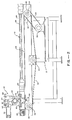
- Referring now to Fig. 2, a side elevation view of the apparatus of Fig. 1 is illustrated. The
bellows 20 is partially removed to show thevacuum chuck 26 and wearplate 28 of the table 12. Mounted totable base 10 is the variable speedelectric motor 30 and speed reducer which drive adouble sprocket 32 mounted on afront axle 34 by means ofchain 36, which inturn drives chain 38.Chain 38 moves over thesprocket 32 on thefront axle 34, sprocket 40 mounted onrear axle 42,idler wheel 44, and drives thecutter bridge assembly 22. As thebridge assembly 22 is moved alongrail 48 by the chain drive, a plurality of micro switches (not shown) are engaged by the cutter bridge assembly to control travel thereof.Limit switches - The bridge assembly is illustrated in Fig. 2 at the extreme left end of travel in engagement with
limit switch 50. Thebellows 20 to the left of the cutter bridge assembly is shown compressed while thebellows 20 to the right of thecutter bridge assembly 22 is shown extended. Thus, the tworails 48 are protected during the travel of thecutter bridge assembly 22 thereon by the expansion and compression of thebellows 20. -
Cutter bridge assembly 22 includes apivot shaft 56 which is rotatably mounted in the assembly and rotatable by means of anair cylinder 58 having apiston shaft 60 mounted topivot lever 62 for rotatingshaft 56.Lever 62 assumes one of three positions by actuation ofcylinder 58 including a neutral position as shown, a left position for engaging a first set of scribe devices through counter clockwise rotation ofpivot shaft 56, and a right position for engaging a second set of scribed devices by clockwise rotation ofpivot shaft 56. Adjustable stops 64 and 66 limit the travel oflever 62 in either the left or right rotational directions.Springs arm 72 opposite fromlever 62 to yieldablybias lever 62 in the neutral position where neither set of scribe devices engage a work piece. - Referring now to Fig. 3, a top view of the apparatus of Fig. 1 is illustrated. In this view a portion of the
cutter bridge assembly 22 is removed to further illustrate thepivot shaft 56 and the front andrear bars pivot shaft 56 for the mounting of scribe devices. The cooperative relationship of the pivot shaft and mounting bars will be further appreciated from the description of Fig. 7 hereinbelow. - A portion of table 12 is removed to illustrative
horizontal members 83 of the frame on which the table is mounted. Additionally, the bellows are removed to show the top ofrail 48 and the top ofrail 84 on the opposite side of table 12 fromrail 48.Motor 30 drivesfront axle 34 by means ofchain 36 which engagessprocket 32 mounted onaxle 34.Axle 34 in turn driveschain 38 which is mounted on sprocket means tofront axle 34,rear axle 42, andidler wheel 44. On the opposite side of the table is asecond chain 88 which is mounted to sprocket 89 on the front axle,sprocket 93 on the rear axle, and anidler wheel 94. Thus, it will be appreciated that movement of thecutter bridge assembly 22 alongrails cutter bridge assembly 22, synchronized drive and improved accuracy in movement of the assembly is realized. - Referring now to Fig. 4, a front elevation of the apparatus of Fig. 1 is illustrated with portions of the apparatus removed to further illustrate elements of the structure. The
pivot shaft 56 of thecutter bridge assembly 22 is rotated from the left end by means ofair cylinder 58 andlever 62, and on the right end of thepivot shaft 56 is a similar air cylinder 58' and lever 62' for rotating the shaft.Bar 80 for mounting of scribe devices (not shown) is shown attached to the front side ofpivot shaft 56.Solenoid 90 for controlling the air cylinders is mounted ontop brace 86 of the assembly. - The table 12 including
wear plate 28 andchuck 26 is mounted onframe 10 by means of flat head adjustment screws 91 which adjust the height of the table 12 for leveling purposes. In one embodiment twenty such adjustable flat head set screws are supported on the horizontal bars 83 (Fig. 3) to support the vacuum chuck and wear plate which comprise the table 12. Locatingposts 93 are provided for positioning the table. - A portion of the
frame 10 is removed to illustrate thefront axle 34 on whichdrive chain cutter bridge assembly 22. Thecutter bridge assembly 22 is mounted on linear bearings ontracks - Fig. 5 is a front elevation view of the
cutter bridge assembly 22 and further illustrates the mounting ofpivot shaft 56 in the assembly by means of bearing 92. A similar bearing arrangement is provided in the other end of the assembly for supporting the pivot shaft.Bearing 92 is mounted in the assembly directly abovesaddle member 94 which accommodates the linear bearing for travel along the rail. Depending fromsaddle 94 isclamp 96 to which the drive chain is attached and which engages the micro switches positioned along the track as the assembly moves from one end of the table to the other. Screw stops 64, 66 are mounted at the upper portion of the assembly to limit the rotational movement of thepivot shaft 56 upon actuation ofair cylinder 58.Arm 62 is mounted to the shaft by means of acollar 98, andarm 62 is actuated by theair cylinder 58 to rotateshaft 56. - Mounted on
support bar 80 is a scribe device shown generally at 100. Mounting of thescribe device 100 to bar 80 will be further described with reference to Fig. 7 below. -
Solenoid 90 is mounted onbrace 86 and controls the application of pressure to aircylinders 58 and 58'. - Fig. 6 is an enlarged side elevation of the
cutter bridge assembly 22 illustrating the mounting and cooperative relationship ofair cylinder 58 having itspiston shaft 60 attached to lever 62 for rotation ofpivot shaft 56.Screws lever 62 by engagingwheel 63 mounted on one end of thelever 62 upon rotation oflever 62 either right or left.Springs arm 72 depending fromcollar 98 to yieldably bias the lever in a neutral position as shown.Saddle 94 including the linear bearing for engagingrail 48 includes thechain clamp 96. - Fig. 7 is a section view of the
cutter bridge assembly 22 taken along lines 7-7 of Fig. 5 and further illustrates the mounting of thescribe devices 100 onbars pivot shaft 56. As will be illustrated in greater detail in Fig. 8, eachscribe device 100 has a surface which mates with the dovetail surface of thebars retractable arm 102 which is locked to the dovetail surface ofbar 80 by means ofscrew 104 and which is released from the dovetail assembly by releasingscrew 104. At the other end of eachscribe device 100 is thescribing element 106 which includes a hard (e.g. tungsten carbide) tip orwheel 108. The scribe device is illustrated and described in more detail with reference to Fig. 8. - Referring now to Figs. 8 and 9, the
scribe device 100 is shown in greater detail with portions thereof removed to illustrate the mounting of elements of the device. The scribe device is shown attached to the dovetail surface ofbar 80 witharm 102 locked into engagement withbar 80 by means ofscrew 104.Screw 104 extends through themain body 112 of the device andspring 114 yieldably maintainsarm 102 in engagement withbar 80 whenscrew 104 is retracted, thereby facilitating the sliding of the scribe device along the bar while preventing the scribe device from falling from thesupport bar 80. - The scribe
support rocker arm 106 is pivotally mounted onbody 112 by means of a support shaft which is clamped inbody 112 by lockingscrew 110. By rotatinghead 116 the scribe element can be moved with respect to the support shaft andbody 112 of the scribe device thereby providing a fine alignment of thescribe point 108.Scribe 108 is preferably a small disc which is mounted on asupport element 117 which is maintained in a receiving cavity inrocker arm 106 by means ofthumb screw 118. - It will be noted in Fig. 8 that the
scribe point 108 is offset from thebody 112 of the scribe device. This offset allows thearm 106 to pivot as the scribe is rotated into engagement with a work piece. A desired pressure is maintained on the scribe point by means ofspring 120 which is attached between one end ofarm 106 and asupport rod 122 mounted inbody 112 by means of ascrew 123.Nut 124 threadably engagesmember 126 and tension exerted byspring 120 can be adjusted by movingnut 124 onmember 126. Anotherrod 128 is attached tobody 112 by means of ascrew 130 and threadably supports screw 132 which limits the travel ofarm 106 in response to the tension ofspring 120. Screw 134 threadably engagesrod 128 and when inserted locksthumb screw 132. - Referring now to Fig. 10, a schematic diagram of the pneumatic control for the vacuum chuck is illustrated. In this embodiment the cutting table 12 is divided into four quadrants designated 12-1, 12-2, 12-3, and 12-4. Thus, a work piece can be floated by air pressure or attached by vacuum to any one or all of the quadrants. Vacuum and pressure for each quadrant is controlled by means of
solenoid valves valve 150, energization and movement of the solenoid to the right applies pressure through valve andline 158 to table quadrant 12-1. Conversely, energization and movement of the solenoid to the left pulls a vacuum throughline 158 on quadrant 12-1. Checkvalves line 158 whereby the vacuum pulled on the cutting table is through afilter 164 to remove any particles from the table. Electrical control of the solenoid 150-156 is illustrated below in the control circuitry in Fig. 14 and more specifically in Figs. 15 and 17. - Fig. 11 is a schematic diagram of the pneumatic control of the
air cylinders 58, 58' of the cutter bridge assembly. Air pressure is applied throughline 170 to the two air cylinders in parallel depending on the setting ofsolenoid 90.Mufflers solenoid 90 to the right applies pressure to the top chambers (as illustrated) of the air cylinders thereby forcing the pistons of the air cylinders out. Energization movement of the solenoid to the left applies pressure to the bottom chambers of the air cylinders thereby pushing the pistons upwardly and pulling in the air cylinder shafts. Control ofsolenoid 90 by relay means is described below in the electrical schematic of Fig. 14. - Figs. 12 and 13 illustrate camming surfaces 180 and 182 of the
switch engaging member 96 of the cutter bridge assembly (see Fig. 5). As shown in Fig. 12, the limit switches 50 and 52 (as shown in Fig. 1) and designated S-1 and S-6, respectively, are engaged bycam surface 180 when the cutter bridge assembly moves to the limit of travel along the two rails. In Fig. 13cam surface 182 engages switches designated S-2, S-3, S-4 and S-5 which are movably positionable along the rail to establish lengths of travel of the cutter bridge assembly during a scribing operation. The switches S-1 through S-6 are further identified in the control circuitry illustrated in Fig. 14. - Referring now to Fig. 14 a functional block diagram of control circuitry for the apparatus of Fig. 1 is illustrated. The control circuitry allows an automatic mode of apparatus operation and a manual mode of apparatus operation. Further, an operator A console is provided at one end of the table (designated the A end) and an operator B console is provided at the other end of the table (designated the B end) to control the operation for concurrent use by two or more operators. Moreover, at both ends of the apparatus provision is made for one operator on the left quadrant and for another operator on the right quadrant.
- In the manual mode of operation, the operator can manually set switch means to move the cutter bridge assembly forward and back, rotate the cutter bridge assembly whereby either the front cutters or the rear cutters are rotated to engage a work piece, and control the vacuum and float (pressure) to the vacuum chuck of the table quadrant in which the operator is working.
- The primary components of the control circuitry include a
master console 190,preprocess logic 192, andcontrol logic 194. Also provided is anoperator A console 196 and anoperator B console 198. The operators are provided also with anA foot switch 200 and aB foot switch 202, respectively, whereby the operators can start the automatic mode of operation after positioning of the work piece. Safety interlock is provided to stop operation in either of the A or B quadrants byswitches -
Master console 190 provides inputs to thepreprocess logic 192 including an automatic mode signal, rear scribe operation, double scribe (scribing both directions of travel of the bridge assembly), long glass (in which intermediate micro switches are not employed), bridge forward, bridge back, cutter front operation, cutter near operation, and a master kill signal for stopping all operation of the apparatus. Themaster console 190 also provides a speed control signal to the drive motor of the bridge assembly. -
Preprocess logic 192 includes voltage level adjustment circuitry to regulate the input voltages for compatibility with thecontrol logic 194. Additionally, the preprocess logic responds to the fail safe and kill operation input signals. - The
preprocess logic 192 provides the following output logic signals:
-
Control logic 194 receives the above input signals from thepreprocess logic 192 and in response thereto controls the sequence of operation of the vacuum chuck, cutter bridge assembly movement, and engagement of the scribe devices. The control logic provides a direction (forward, reverse) and power signal tomotor relay 214.Motor relay 214 also receives the speed control signal from themaster console 190 and controls the speed and direction of thedrive motor 30 throughcontroller 216. 115 volts AC power is provided to the controller as indicated.Motor relay 214 also provides a fail safe sginal back to thepreprocess logic 192. -
Control logic 194 also provides the CW, CCW, and stop signals to the bridge and interlock relays 220, which are operated from +24 volts dc. The bridge andinterlock 220 provides control signals to bridge 22 including cutter front and cutter rear control signals to the solenoid controlling the air cylinders of thebridge 22. - The
bridge interlock 220 also includes a fail safe circuit which is connected through switch S1 and switch S6. Movement of thebridge 22 along the rails to either end of the track whereby either switch S1 or switch S6 is engaged interrupts the fail safe circuit, and thebridge interlock 220 in response thereto generates a kill interlock signal which is fed back tomaster control 190. -
Control logic 194 also provides signals to lamp driver circuits for energizing lamps in themaster control 190, as indicated. - Fig. 15 and Fig. 17 are logic diagrams for the
preprocess logic 192 and thecontrol logic 194, respectively. The following circuits commercially available from Motorola, Inc. were used in the construction of one specific embodiment:
- In Fig. 15, the
preprocess logic 192 includes voltagelevel adjustment circuitry 230 which receives the inputs listed on the left side of the diagram and adjusts the input levels to 0 and +15 volts for compatibility with the control logic. Thelevel adjustment circuitry 230 is shown schematically in Fig. 16 and includes a Motorola MC696TL differential amplifier which is operated from a +15 volt supply. - Most of the input signals after voltage level adjustment are ready as inputs for the control logic. However, some signals are dependent upon other inputs or require storage in memory elements before they can be used by the control logic. These signals are the DSC, LONG, S3 or S5, rear scribe and auto output signals.
- Referring to Fig. 17, the control logic receives the level adjusted and processed signals from the preprocess logic and operates on the input signals to generate the apparatus control signals in safe and sequential steps.
- Following is the operating sequence for several modes of operating:
- Single scribe regular glass
- a. Machine set up. Cutting depth and scribing speed.
- 1. Move the bridge toward the main operator side by pushing "bridge forward" pushbutton and holding until bridge is in desired location.
- 2. To lower the cutters nearest the main operator side, momentarily push the "cut fwd" pushbutton. The cutters will remain in position as long as the pushbutton head is lit. To raise the cutters momentarily press the "cut fwd" pushbutton again.
- 3. When the cutter set up has been completed, move the bridge to the center of the table by pressing the "bridge reverse" pushbutton.
- 4. Adjust the cutting speed with the speed control knob.
- 5. The set up procedure for the other side of the table is identical to that described above except that the cutters must be lowered with the "cutter rev" pushbutton.
- b. Automatic scribe operation
- 1 Press the "auto" pushbutton. When the pushbutton is illuminated the machine is in the automatic mode.
- 2. Both operators press their respective start switches as required to scribe glass on their side.
- c. Stop scribe cycle
- 1. For minor changes stop the scribe cycle by momentarily pressing the "stop" pushbutton. The scribe cycle stops short and the bridge returns to the start position.
- 2. For major problems hit any one of the 4 kill buttons. The bridge halts and raises the cutters.
- a. Machine set up. Cutting depth and scribing speed.
- Doublescribe regular glass (both operators).
- a. Set up as before for single scribes.
- 1. Adjust the front and rear cutters by pushing the proper "cut fwd" and "cut rev" pushbuttons. Pressing both buttons simultaneously raises both sets of cutters.
- 2. Locate the work to be scribed on the table so that the cutters away from the operator start their scribes at the front edge of the glass.
- b. Automatic scribe operation.
- 1. Press the "auto" pushbutton first then the "double-scribe" pushbutton. When both buttons are illuminated, the machine will perform the doublescribe operation.
- 2. Scribe glass as desired.
- c. The stop scribing as before for single scribes.
- X X X X X
- X X X X X
- Scribe long glass
- a. Set up as before for single scribes.
- b. Automatic scribe operation.
-
- 1. Press the "auto" button.
- 2. Press the "long glass" pushbutton. If both "auto" and "long glass" pushbuttons are lit the machine will scribe long glass.
- 3. Only the main operator is able to scribe by pushing his start switch. Pushing the start switch on the other side has no affect of the machine.
- c. Stop the scribe cycle as before for single scribes.
-
- Doubescribe long glass
- a. Set up as before for single scribes.
- b. Automatic scribe operation as before for long glass scribing, except that the "double- scribe" pushbutton must be pushed after the other two.
- c. Stop the scribe cycle as before for single scribes.
- Resetting the machine after a "kill" pushbutton has been pressed.
- a. Clear the source of the problem.
- b. Press the "stop" pushbutton.
- c. Move the bridge to the center of the table with the appropriate "bridge forward" or "bridge reverse" pushbutton.
- d. Press the "auto" pushbutton and any other options (long or doublescribe).
- e. Proceed to scribe as before.
- Resetting the machine after it has traveled into the stops.
- a. Move the bridge out of the stop area by pushing the bridge toward the center of the table.
- b. Once out of the stops determine why the bridge overtraveled and make appropriate corrections and adjustment.
- c. Reset the electronics by following the sequence described for resetting a "kill".
- Limit switch function (switches S2-S5)
- a. When single scribing short glass, the main operation has started his cycle:
- 1. The bridge encounters S3 and lowers the cutterheads.
- 2. The bridge encounters S2, raises cutters and reverses direction of travel.
- 3. The bridge encounters S3 and stops.
- 4. When the other operator begins his sequence S4 and S5 perform the cutter head operation and turnaround as required.
- b. When doublescribing short glass; the main operator has started his cycle:

- c. When scribing long glass, bridge parked at S5.X X X X X

- d. When doublescribing long glass; operation is the same as for long glass except that front cutters raise and rear cutters lower at S2 and all cutters raise at S5.
- e. When rear scribing; bridge parked at S5.


- While the invention has been described with reference to a specific embodiment, the description is for illustration purposes and is not to be construed as limiting the scope of the invention. Various modifications, adaptations, and other changes may occur to those skilled in the art without departing from the true spirit and scope of the invention as defined by the appended claims.
- As can be seen from the above description the invention provides among others a scribing apparatus which allows a plurality of operators. to concurrently process material, a scribing apparatus having manual and automatic modes of operation, a scribing apparatus having a vacuum chuck table with vacuum control means for a plurality of portions of the table, a bridge assembly mounted on track means for movement by drive means of each end of the bridge assembly, a scribing device which engages a dovetail guide bar in the bridge assembly and is slidable thereon for positioning and which includes also fine adjustment positioning means, track means provided on either side of the chuck means, and a bridge assembly moveably mounted on the track means, and preferably, is the drive means provided on either end of the bridge assembly to facilitate accurate movement thereof, the scribing means preferably engage dovetail guide bars mounted on the rotatable shaft whereby the scribing means can be readily removed from the guide bar, slid along the guide bar, and locked to the guide bar.
Claims (11)
Applications Claiming Priority (2)
| Application Number | Priority Date | Filing Date | Title |
|---|---|---|---|
| US963314 | 1978-11-24 | ||
| US05/963,314 US4221150A (en) | 1978-11-24 | 1978-11-24 | Glass scribing apparatus |
Publications (2)
| Publication Number | Publication Date |
|---|---|
| EP0011832A1 EP0011832A1 (en) | 1980-06-11 |
| EP0011832B1 true EP0011832B1 (en) | 1982-12-22 |
Family
ID=25507059
Family Applications (1)
| Application Number | Title | Priority Date | Filing Date |
|---|---|---|---|
| EP19790104654 Expired EP0011832B1 (en) | 1978-11-24 | 1979-11-22 | Scribing apparatus |
Country Status (4)
| Country | Link |
|---|---|
| US (1) | US4221150A (en) |
| EP (1) | EP0011832B1 (en) |
| CA (1) | CA1112150A (en) |
| DE (1) | DE2964382D1 (en) |
Families Citing this family (22)
| Publication number | Priority date | Publication date | Assignee | Title |
|---|---|---|---|---|
| USD276528S (en) | 1982-04-12 | 1984-11-27 | Shaffer Myron W | Scoring device for laminated sheet material |
| GB2124612B (en) * | 1982-07-16 | 1986-07-23 | Planters Powergrind | Glass cutting head arrangement |
| US4665619A (en) * | 1983-01-24 | 1987-05-19 | Gerber Garment Technology, Inc. | Method and apparatus for working on sheet material |
| US4736661A (en) * | 1986-09-22 | 1988-04-12 | Takaaki Shirai | Cutting apparatus |
| IT1222060B (en) * | 1987-07-17 | 1990-08-31 | Vetreria Lorenzo Snc Di Giorgi | AUTOMATIC EQUIPMENT PARTICULARLY DESIGNED FOR CUTTING SINGLE AND DOUBLE GLASS SHEETS |
| US4951539A (en) * | 1989-07-05 | 1990-08-28 | Buckner James A | Apparatus for cutting duct board and the like |
| AT403908B (en) * | 1994-07-04 | 1998-06-25 | Lisec Peter | ARRANGEMENT FOR DIVIDING COMPOSITE GLASS |
| US5825652A (en) * | 1995-09-08 | 1998-10-20 | Gerber Garment Technology, Inc. | Sample garment making system |
| US7085854B2 (en) | 2000-04-12 | 2006-08-01 | Corente, Inc. | Methods and systems for enabling communication between a processor and a network operations center |
| US6631416B2 (en) | 2000-04-12 | 2003-10-07 | Openreach Inc. | Methods and systems for enabling a tunnel between two computers on a network |
| US7028334B2 (en) | 2000-04-12 | 2006-04-11 | Corente, Inc. | Methods and systems for using names in virtual networks |
| CN100556836C (en) * | 2003-08-11 | 2009-11-04 | 彼得·利泽克 | glass cutting table |
| CN1906003B (en) * | 2003-12-29 | 2010-12-08 | 三星钻石工业株式会社 | Marking head and marking equipment |
| US7392732B2 (en) | 2005-01-24 | 2008-07-01 | Micro Processing Technology, Inc. | Scribing tool and method |
| US7415916B2 (en) * | 2005-01-24 | 2008-08-26 | Micro Processing Technology, Inc. | Scribing system with particle remover |
| KR101242236B1 (en) * | 2005-12-01 | 2013-03-11 | 미쓰보시 다이야몬도 고교 가부시키가이샤 | Tip holder |
| US9138910B2 (en) * | 2005-12-01 | 2015-09-22 | Mitsuboshi Diamond Industrial Co., Ltd. | Scribe device, scribe method, and tip holder |
| US20090044676A1 (en) * | 2007-08-15 | 2009-02-19 | Jourdan James K | Power tilt assembly for band saw |
| KR101703026B1 (en) * | 2014-08-29 | 2017-02-07 | 주식회사 태성기연 | Suction equipment for a display panel |
| CN111247104B (en) * | 2017-09-26 | 2022-10-21 | 康宁公司 | Glass manufacturing apparatus and method for separating glass ribbon |
| CN109571347B (en) * | 2018-12-29 | 2023-10-20 | 昆山拓誉自动化科技有限公司 | Stacked station for flat lamp assembly line |
| CN109938452A (en) * | 2019-04-25 | 2019-06-28 | 东莞职业技术学院 | A kind of table above formula pen machine |
Family Cites Families (11)
| Publication number | Priority date | Publication date | Assignee | Title |
|---|---|---|---|---|
| US728417A (en) * | 1901-03-22 | 1903-05-19 | Henry J Sage | Glass-cutting apparatus. |
| US1852310A (en) * | 1925-08-24 | 1932-04-05 | G W Klages And Son Inc | Multiple glass cutting machine |
| US2357206A (en) * | 1942-03-14 | 1944-08-29 | American Window Glass Co | Apparatus for scoring cover glass |
| US3222963A (en) * | 1964-03-11 | 1965-12-14 | Nabiullin Faat Hatovich | Device for scoring of crystalline semiconductor materials |
| US3286893A (en) * | 1965-09-01 | 1966-11-22 | Libbey Owens Ford Glass Co | Method and apparatus for automatic glass cutting |
| US3424357A (en) * | 1966-07-28 | 1969-01-28 | Ppg Industries Inc | Automatically sizing and severing glass sheets |
| FR1526313A (en) * | 1967-04-14 | 1968-05-24 | Boussois Souchon Neuvesel Sa | Glass cutting device |
| US3574976A (en) * | 1968-02-05 | 1971-04-13 | Permaglass | Method for cutting and grinding glass |
| US3715945A (en) * | 1969-10-31 | 1973-02-13 | Mutoh Ind Ltd | Automatische schneidemaschine |
| IT963880B (en) * | 1972-08-10 | 1974-01-21 | S Bottero E C Sa | IMPROVEMENTS RELATING TO TABLE LI FOR CUTTING GLASS SHEETS |
| US3859878A (en) * | 1973-08-22 | 1975-01-14 | Ppg Industries Inc | Apparatus for ganged scoring of glass |
-
1978
- 1978-11-24 US US05/963,314 patent/US4221150A/en not_active Expired - Lifetime
-
1979
- 1979-11-22 DE DE7979104654T patent/DE2964382D1/en not_active Expired
- 1979-11-22 EP EP19790104654 patent/EP0011832B1/en not_active Expired
- 1979-11-23 CA CA340,489A patent/CA1112150A/en not_active Expired
Also Published As
| Publication number | Publication date |
|---|---|
| DE2964382D1 (en) | 1983-01-27 |
| CA1112150A (en) | 1981-11-10 |
| EP0011832A1 (en) | 1980-06-11 |
| US4221150A (en) | 1980-09-09 |
Similar Documents
| Publication | Publication Date | Title |
|---|---|---|
| US4221150A (en) | Glass scribing apparatus | |
| US3566932A (en) | Process for rational production of size plates with a plate saw, in particular using an electronic control and device for practicing | |
| US4934422A (en) | Bench mountable plate joining machine | |
| US4185943A (en) | Drilling and tapping machining apparatus | |
| US5888268A (en) | Glass-plate working apparatus | |
| US3880048A (en) | Apparatus for cutting irregular edge contours in relatively flat workpieces | |
| ES2176532T3 (en) | PROCEDURE AND DEVICE FOR CONTROLLING THE ADVANCE DRIVE DRIVEN BY A MOTOR. | |
| US3713637A (en) | Portable flame cutting machine | |
| EP0539633B1 (en) | Gantry-type machine tool | |
| US4610582A (en) | Roller hold down device | |
| EP0569737B1 (en) | Adjustable length carriage compatible for use with differing spreading table widths and types | |
| JPH0760523A (en) | Cutting device in beveling machine | |
| US4519139A (en) | Device for automatic marking out and dividing up of a flat sheet of glass which can be positioned upstream of a sheet cutting line | |
| US3583270A (en) | Slitters for travelling webs | |
| US4677726A (en) | Milling machine apparatus | |
| US4243084A (en) | Door sizing machine | |
| US946635A (en) | Machine for grinding straight machine-knives. | |
| EP0065834A2 (en) | Machine tool with twin work tables | |
| JPH06171967A (en) | Glass substrate cutting device | |
| US2168234A (en) | Grooving machine | |
| EP0296390A2 (en) | Grinder for engraving glass, mirrors and the like | |
| EP0197233B1 (en) | A machine for working circular profile edges of slabs of marble, granite, and the like | |
| US5219011A (en) | Hinge slotting machine | |
| CN115178767B (en) | A drilling device for civil defense engineering | |
| JP2678487B2 (en) | Cutting method |
Legal Events
| Date | Code | Title | Description |
|---|---|---|---|
| PUAI | Public reference made under article 153(3) epc to a published international application that has entered the european phase |
Free format text: ORIGINAL CODE: 0009012 |
|
| AK | Designated contracting states |
Designated state(s): BE CH DE FR GB IT LU NL |
|
| 17P | Request for examination filed | ||
| ITF | It: translation for a ep patent filed | ||
| GRAA | (expected) grant |
Free format text: ORIGINAL CODE: 0009210 |
|
| AK | Designated contracting states |
Designated state(s): BE CH DE FR GB IT LU NL |
|
| ET | Fr: translation filed | ||
| REF | Corresponds to: |
Ref document number: 2964382 Country of ref document: DE Date of ref document: 19830127 |
|
| PGFP | Annual fee paid to national office [announced via postgrant information from national office to epo] |
Ref country code: LU Payment date: 19831006 Year of fee payment: 5 |
|
| PGFP | Annual fee paid to national office [announced via postgrant information from national office to epo] |
Ref country code: FR Payment date: 19831123 Year of fee payment: 5 |
|
| PGFP | Annual fee paid to national office [announced via postgrant information from national office to epo] |
Ref country code: NL Payment date: 19831129 Year of fee payment: 5 |
|
| PG25 | Lapsed in a contracting state [announced via postgrant information from national office to epo] |
Ref country code: LU Free format text: LAPSE BECAUSE OF NON-PAYMENT OF DUE FEES Effective date: 19831130 |
|
| PGFP | Annual fee paid to national office [announced via postgrant information from national office to epo] |
Ref country code: DE Payment date: 19831220 Year of fee payment: 5 |
|
| PGFP | Annual fee paid to national office [announced via postgrant information from national office to epo] |
Ref country code: CH Payment date: 19831222 Year of fee payment: 5 |
|
| PGFP | Annual fee paid to national office [announced via postgrant information from national office to epo] |
Ref country code: BE Payment date: 19831231 Year of fee payment: 5 |
|
| PG25 | Lapsed in a contracting state [announced via postgrant information from national office to epo] |
Ref country code: CH Effective date: 19841130 Ref country code: BE Effective date: 19841130 |
|
| BERE | Be: lapsed |
Owner name: OPTICAL COATING LABORATORY INC. Effective date: 19841122 |
|
| PG25 | Lapsed in a contracting state [announced via postgrant information from national office to epo] |
Ref country code: NL Effective date: 19850601 |
|
| GBPC | Gb: european patent ceased through non-payment of renewal fee | ||
| NLV4 | Nl: lapsed or anulled due to non-payment of the annual fee | ||
| PG25 | Lapsed in a contracting state [announced via postgrant information from national office to epo] |
Ref country code: FR Free format text: LAPSE BECAUSE OF NON-PAYMENT OF DUE FEES Effective date: 19850731 |
|
| REG | Reference to a national code |
Ref country code: CH Ref legal event code: PL |
|
| PG25 | Lapsed in a contracting state [announced via postgrant information from national office to epo] |
Ref country code: DE Effective date: 19850801 |
|
| REG | Reference to a national code |
Ref country code: FR Ref legal event code: ST |
|
| PG25 | Lapsed in a contracting state [announced via postgrant information from national office to epo] |
Ref country code: GB Effective date: 19881118 |
|
| PLBE | No opposition filed within time limit |
Free format text: ORIGINAL CODE: 0009261 |
|
| STAA | Information on the status of an ep patent application or granted ep patent |
Free format text: STATUS: NO OPPOSITION FILED WITHIN TIME LIMIT |