EP0011289B1 - Valve - Google Patents
Valve Download PDFInfo
- Publication number
- EP0011289B1 EP0011289B1 EP79104499A EP79104499A EP0011289B1 EP 0011289 B1 EP0011289 B1 EP 0011289B1 EP 79104499 A EP79104499 A EP 79104499A EP 79104499 A EP79104499 A EP 79104499A EP 0011289 B1 EP0011289 B1 EP 0011289B1
- Authority
- EP
- European Patent Office
- Prior art keywords
- diaphragm
- valve
- closure member
- central
- bolt
- Prior art date
- Legal status (The legal status is an assumption and is not a legal conclusion. Google has not performed a legal analysis and makes no representation as to the accuracy of the status listed.)
- Expired
Links
- 239000012530 fluid Substances 0.000 claims description 24
- 238000007789 sealing Methods 0.000 description 7
- 230000008878 coupling Effects 0.000 description 3
- 238000010168 coupling process Methods 0.000 description 3
- 238000005859 coupling reaction Methods 0.000 description 3
- 238000003466 welding Methods 0.000 description 3
- 230000000694 effects Effects 0.000 description 2
- 239000000470 constituent Substances 0.000 description 1
- 230000002093 peripheral effect Effects 0.000 description 1
Images

Classifications
-
- F—MECHANICAL ENGINEERING; LIGHTING; HEATING; WEAPONS; BLASTING
- F16—ENGINEERING ELEMENTS AND UNITS; GENERAL MEASURES FOR PRODUCING AND MAINTAINING EFFECTIVE FUNCTIONING OF MACHINES OR INSTALLATIONS; THERMAL INSULATION IN GENERAL
- F16K—VALVES; TAPS; COCKS; ACTUATING-FLOATS; DEVICES FOR VENTING OR AERATING
- F16K5/00—Plug valves; Taps or cocks comprising only cut-off apparatus having at least one of the sealing faces shaped as a more or less complete surface of a solid of revolution, the opening and closing movement being predominantly rotary
- F16K5/06—Plug valves; Taps or cocks comprising only cut-off apparatus having at least one of the sealing faces shaped as a more or less complete surface of a solid of revolution, the opening and closing movement being predominantly rotary with plugs having spherical surfaces; Packings therefor
- F16K5/0663—Packings
- F16K5/0684—Packings on the plug
-
- F—MECHANICAL ENGINEERING; LIGHTING; HEATING; WEAPONS; BLASTING
- F16—ENGINEERING ELEMENTS AND UNITS; GENERAL MEASURES FOR PRODUCING AND MAINTAINING EFFECTIVE FUNCTIONING OF MACHINES OR INSTALLATIONS; THERMAL INSULATION IN GENERAL
- F16K—VALVES; TAPS; COCKS; ACTUATING-FLOATS; DEVICES FOR VENTING OR AERATING
- F16K5/00—Plug valves; Taps or cocks comprising only cut-off apparatus having at least one of the sealing faces shaped as a more or less complete surface of a solid of revolution, the opening and closing movement being predominantly rotary
- F16K5/08—Details
- F16K5/14—Special arrangements for separating the sealing faces or for pressing them together
- F16K5/20—Special arrangements for separating the sealing faces or for pressing them together for plugs with spherical surfaces
- F16K5/204—Special arrangements for separating the sealing faces or for pressing them together for plugs with spherical surfaces with the plugs or parts of the plugs mechanically pressing the seals against the housing
Definitions
- the invention relates to a valve including a valve housing, a tubular valve closure member having an inner diameter substantially equal to the diameter of the fluid passage within the valve housing and mounted to be rotatable within the valve housing around an axis normal to the direction of the fluid flow, an elastically flexible, substantially disc-shaped diaphragm provided on the valve closure member, a valve seat provided within the valve housing and having a contact surface to contact the diaphragm, the contact surface being spherically shaped to correspond to a portion of the surface of an imaginary sphere having its centre at the intersection of the rotational axis of the valve closure member and the central axis of the disc-shaped diaphragm, and annular stopper means provided on the valve closure member to contact an annular zone of the diaphragm adjacent to the portion of the diaphragm contacting the valve seat when the valve is closed, for stopping and controlling flexion of the diaphragm under fluid pressure, the central portion of the disc-shaped diaphragm being mounted on the valve closure member.
- a conventional fluid-valve of this type is described in FR-A-2 221 658.
- the rotatable closure member is formed with an annular projection supporting the disc-shaped diaphragm which has its central portion rigidly connected to the valve closure member.
- the fluid pressure existing in the inlet fluid passage flexes the diaphragm into an annular groove formed between the annular projection and the central fastening means of the diaphragm, so that the outer edge of the diaphragm is pressed against the valve seat to produce a good sealing effect.
- the fluid pressure assists the force required to act upon the sealing portion of the diaphragm in order to attain sealing.
- this object is achieved by the central connecting portion of the diaphragm being keyed to the valve closure member to shift in the direction of the central axis thereof under fluid pressure.
- the annular stopper means are adapted to bear against the diaphragm at an intermediate position between its connecting portion and its contacting portion, they not only control the amount of shifting and flexion of the diaphragm under fluid pressure but also cause the diaphragm to flex into pressing contact with the housing about a fulcrum provided by the portion supported by the stopper means under the action of fluid pressure on the portion of the diaphragm between the connecting portion and the supported portion.
- Valve closing operation per se need not be relied upon for flexing the diaphragm to provide it with an elastic force sufficient to resist fluid pressure.
- the valve of this invention is therefore operable with a relatively small force and provides reliable sealing by causing the diaphragm to press upon the valve seat provided at the valve housing with a strong force proportional to the fluid pressure acting on the diaphragm.
- a valve according to the preferred embodiment of this invention includes a valve housing 3 having coupling parts 2 to couple to fluid transmitting pipes 1 and valve seats 4 with spherical surfaces mounted within the valve housing 3.
- a valve closure member 5 is rotatably mounted in the valve housing 3.
- the valve closure member 5 has a tubular form with an inner diameter substantially equal to the diameter of the fluid passage of the valve housing 3.
- a valve stem 6 is provided integral with and extending normally to the axis X of the tubular valve closure member 5, one end of the stem 6 protruding from the housing 3.
- the valve closure member 5 carries, on opposite peripheral sides thereof, elastically flexible sealing members or diaphragms 7 adapted to press-contact the valve seats 4 to entirely shutoff the interior space of the valve housing 3 when the valve is closed.
- the valve is adapted to open and close the fluid passage when a valve operator mechanism 8, operatively connected to the end of the stem 6 protruding from the valve housing 3, is actuated, to cause rotation of the valve closure member 5.
- the valve housing 3 has four constituent sections, namely two sections 3a including the coupling parts 2 and two main sections 3b, interconnected into one body by welding or by mechanical means such as bolting.
- Each of the diaphragms 7 has a disc shape and includes a central connecting portion 9 connected to the valve closure member 5 by means of a bolt 10.
- the valve closure member 5 has annular stopper means 12 integral therewith disposed opposite to an annular zone B of the first seat 7 radially intermediate between connecting portion 9 and a contacting portion 11.
- the stopper means 12 are adapted to abuttingly support the diaphragm 7 and control its shifting and flexion under fluid pressure and to cause the diaphragm 7 to flex about a fulcrum provided by the zone B supported by the stopper means 12 under the action of fluid pressure acting in direction A on the diaphragm 7 between the control connecting portion 9 and the zone B, so that the contacting portion 11 of the diaphragm 7 presses against the valve seat 4.
- valve seat 4 is meshingly attached to the section 3a of the housing 3 which includes the coupling part 2 and is fixed by screws 13.
- This arrangement constitutes a seat adjuster mechanism D for moving the valve seat 4 towards and away from the diaphragm 7 and fixing it in position.
- the bolt 10 is a stepped bolt with a head part 14 keyed as at 1 and a large diameter part 16 radially projecting from the head part 14 and engaging a position control element 17 removably attached to the valve closure member 5, whereby the bolt 10 is prevented from moving towards the valve seat 4.
- the diaphragm 7 includes centrally thereof an opening 18 having a greater diameter than a threaded part 10a of the bolt 10 and a cruciform engaging groove 19 defined in a thickened portion of the diaphragm 7.
- a collar member 21 has a central opening 20 equal in diameter to the central opening 18 and a cruciform boss 22 in engagement with the engaging groove 19, whereby the collar member 21 is engaged with the diaphragm 7.
- This arrangement constitutes a diaphragm adjuster mechanism E.
- the diaphragm adjuster mechanism E is adapted to radially adjust the diaphragm 7 in position opposite to the valve seat 4 within a free range provided by the difference between the inner diameter of the collar member 21 and the outer diameter of the threaded part 10a of the bolt 10.
- the diaphragm 7 positionally adjusted as above is held tight by means of a nut 23, and the nut 23 and the collar 21 are welded together.
- the valve seat 4 is positionally adjusted to to the diaphragm 7.
- the diaphragm 7 and the valve seat 4 are mounted on the valve closure member 5 and the valve housing 3 respectively, so that the diaphragm and the valve seat come into tight contact when the valve is closed.
- Numeral 24 in the drawings denotes an 0- ring provided between the back face of the diaphragm 7 and the head part 14 of the bolt 10 for sealing purposes, to prevent fluid leakage between the central opening 18 and the periphery of the bolt 10.
- the valve seat 4 has a contact surface F to contact the diaphragm 7 shaped to correspond to part of an imaginary sphere having its centre at the intersection of the rotational axis P of the valve closure member 5 and the central axis X of the diaphragm 7.
- the diaphragm 7 and the valve seat 4 are thus adapted for face to face contact to produce a good sealing effect, by adjusting the mounting position of the diaphragm 7 on the valve closure member 5 and that of the valve seat 4 on the valve housing 3.
- the collar member 21 provided on the diaphragm 7 is welded to the nut 23 so that the elastic quality of the diaphragm 7 is not affected by the welding. It is however possible to dispense with the collar member 21 and to weld the diaphragm 7 directly to the nut 23.
- valve housing 3 composed of a plurality of sections 3a, 3b welded together
- the invention is applicable to the type including a valve housing with flange connections.
- annular stopper means 12 It is desirable to dispose the annular stopper means 12 in a position to bear against the diaphragm 7 so as to provide a maximum movement of the contacting portion 11, but the position of the stopper means 12 may be varied to suit specific requirements.
Landscapes
- Engineering & Computer Science (AREA)
- General Engineering & Computer Science (AREA)
- Mechanical Engineering (AREA)
- Lift Valve (AREA)
- Taps Or Cocks (AREA)
Description
- The invention relates to a valve including a valve housing, a tubular valve closure member having an inner diameter substantially equal to the diameter of the fluid passage within the valve housing and mounted to be rotatable within the valve housing around an axis normal to the direction of the fluid flow, an elastically flexible, substantially disc-shaped diaphragm provided on the valve closure member, a valve seat provided within the valve housing and having a contact surface to contact the diaphragm, the contact surface being spherically shaped to correspond to a portion of the surface of an imaginary sphere having its centre at the intersection of the rotational axis of the valve closure member and the central axis of the disc-shaped diaphragm, and annular stopper means provided on the valve closure member to contact an annular zone of the diaphragm adjacent to the portion of the diaphragm contacting the valve seat when the valve is closed, for stopping and controlling flexion of the diaphragm under fluid pressure, the central portion of the disc-shaped diaphragm being mounted on the valve closure member.
- A conventional fluid-valve of this type is described in FR-A-2 221 658. The rotatable closure member is formed with an annular projection supporting the disc-shaped diaphragm which has its central portion rigidly connected to the valve closure member. When this valve is closed, the fluid pressure existing in the inlet fluid passage flexes the diaphragm into an annular groove formed between the annular projection and the central fastening means of the diaphragm, so that the outer edge of the diaphragm is pressed against the valve seat to produce a good sealing effect. Thus, the fluid pressure assists the force required to act upon the sealing portion of the diaphragm in order to attain sealing.
- It is the object of the present invention to reduce further the force to be applied by the valve closure member against the diaphragm and thus to reduce the force which is required to operate and close the valve to seal off fluid reliably.
- According to the invention this object is achieved by the central connecting portion of the diaphragm being keyed to the valve closure member to shift in the direction of the central axis thereof under fluid pressure.
- Since the annular stopper means are adapted to bear against the diaphragm at an intermediate position between its connecting portion and its contacting portion, they not only control the amount of shifting and flexion of the diaphragm under fluid pressure but also cause the diaphragm to flex into pressing contact with the housing about a fulcrum provided by the portion supported by the stopper means under the action of fluid pressure on the portion of the diaphragm between the connecting portion and the supported portion. Valve closing operation per se need not be relied upon for flexing the diaphragm to provide it with an elastic force sufficient to resist fluid pressure. The valve of this invention is therefore operable with a relatively small force and provides reliable sealing by causing the diaphragm to press upon the valve seat provided at the valve housing with a strong force proportional to the fluid pressure acting on the diaphragm.
- In the drawings illustrating a valve embodying the invention,
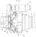
- Figure 1 is a view in vertical section of the valve in its closed position,
- Figure 2 is an enlarged sectional view of a principal part of the valve, and
- Figure 3 is a section taken on line III-III of Figure 1.
- A valve according to the preferred embodiment of this invention includes a
valve housing 3 havingcoupling parts 2 to couple to fluid transmitting pipes 1 andvalve seats 4 with spherical surfaces mounted within thevalve housing 3. Avalve closure member 5 is rotatably mounted in thevalve housing 3. Thevalve closure member 5 has a tubular form with an inner diameter substantially equal to the diameter of the fluid passage of thevalve housing 3. Avalve stem 6 is provided integral with and extending normally to the axis X of the tubularvalve closure member 5, one end of thestem 6 protruding from thehousing 3. Thevalve closure member 5 carries, on opposite peripheral sides thereof, elastically flexible sealing members ordiaphragms 7 adapted to press-contact thevalve seats 4 to entirely shutoff the interior space of thevalve housing 3 when the valve is closed. Thus the valve is adapted to open and close the fluid passage when avalve operator mechanism 8, operatively connected to the end of thestem 6 protruding from thevalve housing 3, is actuated, to cause rotation of thevalve closure member 5. - The
valve housing 3 has four constituent sections, namely twosections 3a including thecoupling parts 2 and twomain sections 3b, interconnected into one body by welding or by mechanical means such as bolting. - Each of the
diaphragms 7 has a disc shape and includes a central connectingportion 9 connected to thevalve closure member 5 by means of abolt 10. Thevalve closure member 5 has annular stopper means 12 integral therewith disposed opposite to an annular zone B of thefirst seat 7 radially intermediate between connectingportion 9 and a contacting portion 11. The stopper means 12 are adapted to abuttingly support thediaphragm 7 and control its shifting and flexion under fluid pressure and to cause thediaphragm 7 to flex about a fulcrum provided by the zone B supported by the stopper means 12 under the action of fluid pressure acting in direction A on thediaphragm 7 between thecontrol connecting portion 9 and the zone B, so that the contacting portion 11 of thediaphragm 7 presses against thevalve seat 4. - The
valve seat 4 is meshingly attached to thesection 3a of thehousing 3 which includes thecoupling part 2 and is fixed byscrews 13. This arrangement constitutes a seat adjuster mechanism D for moving thevalve seat 4 towards and away from thediaphragm 7 and fixing it in position. - The
bolt 10 is a stepped bolt with ahead part 14 keyed as at 1 and alarge diameter part 16 radially projecting from thehead part 14 and engaging aposition control element 17 removably attached to thevalve closure member 5, whereby thebolt 10 is prevented from moving towards thevalve seat 4. As shown in Figure 3, thediaphragm 7 includes centrally thereof anopening 18 having a greater diameter than a threadedpart 10a of thebolt 10 and a cruciformengaging groove 19 defined in a thickened portion of thediaphragm 7. Acollar member 21 has acentral opening 20 equal in diameter to thecentral opening 18 and acruciform boss 22 in engagement with theengaging groove 19, whereby thecollar member 21 is engaged with thediaphragm 7. This arrangement constitutes a diaphragm adjuster mechanism E. - The diaphragm adjuster mechanism E is adapted to radially adjust the
diaphragm 7 in position opposite to thevalve seat 4 within a free range provided by the difference between the inner diameter of thecollar member 21 and the outer diameter of the threadedpart 10a of thebolt 10. Thediaphragm 7 positionally adjusted as above is held tight by means of anut 23, and thenut 23 and thecollar 21 are welded together. Then thevalve seat 4 is positionally adjusted to to thediaphragm 7. Thus thediaphragm 7 and thevalve seat 4 are mounted on thevalve closure member 5 and thevalve housing 3 respectively, so that the diaphragm and the valve seat come into tight contact when the valve is closed. - Numeral 24 in the drawings denotes an 0- ring provided between the back face of the
diaphragm 7 and thehead part 14 of thebolt 10 for sealing purposes, to prevent fluid leakage between thecentral opening 18 and the periphery of thebolt 10. - The
valve seat 4 has a contact surface F to contact thediaphragm 7 shaped to correspond to part of an imaginary sphere having its centre at the intersection of the rotational axis P of thevalve closure member 5 and the central axis X of thediaphragm 7. Thediaphragm 7 and thevalve seat 4 are thus adapted for face to face contact to produce a good sealing effect, by adjusting the mounting position of thediaphragm 7 on thevalve closure member 5 and that of thevalve seat 4 on thevalve housing 3. - In the above embodiment, the
collar member 21 provided on thediaphragm 7 is welded to thenut 23 so that the elastic quality of thediaphragm 7 is not affected by the welding. It is however possible to dispense with thecollar member 21 and to weld thediaphragm 7 directly to thenut 23. - While this invention, as applied to the type of valve including a
valve housing 3 composed of a plurality ofsections - It is desirable to dispose the annular stopper means 12 in a position to bear against the
diaphragm 7 so as to provide a maximum movement of the contacting portion 11, but the position of the stopper means 12 may be varied to suit specific requirements.
Claims (4)
Applications Claiming Priority (4)
| Application Number | Priority Date | Filing Date | Title |
|---|---|---|---|
| JP140763/78 | 1978-11-14 | ||
| JP14076378A JPS5814952B2 (en) | 1978-11-14 | 1978-11-14 | Valve seal structure |
| JP3070179A JPS55123053A (en) | 1979-03-15 | 1979-03-15 | Valve seal |
| JP30701/79 | 1979-03-15 |
Publications (2)
| Publication Number | Publication Date |
|---|---|
| EP0011289A1 EP0011289A1 (en) | 1980-05-28 |
| EP0011289B1 true EP0011289B1 (en) | 1983-05-04 |
Family
ID=26369102
Family Applications (1)
| Application Number | Title | Priority Date | Filing Date |
|---|---|---|---|
| EP79104499A Expired EP0011289B1 (en) | 1978-11-14 | 1979-11-14 | Valve |
Country Status (3)
| Country | Link |
|---|---|
| US (1) | US4372532A (en) |
| EP (1) | EP0011289B1 (en) |
| DE (1) | DE2965325D1 (en) |
Families Citing this family (3)
| Publication number | Priority date | Publication date | Assignee | Title |
|---|---|---|---|---|
| AU626826B2 (en) * | 1989-01-30 | 1992-08-13 | Valtek Incorporated | Multi-element, bi-directional valve seat |
| US5193573A (en) * | 1992-06-15 | 1993-03-16 | Chronister Clyde H | Ball valve having replaceable seals under full service pressure |
| CN116677793B (en) * | 2023-06-07 | 2026-04-28 | 上海开维喜阀门有限公司 | A novel bidirectional sealing lifting rod ball valve |
Family Cites Families (14)
| Publication number | Priority date | Publication date | Assignee | Title |
|---|---|---|---|---|
| GB271095A (en) * | 1927-05-12 | 1928-03-15 | Walter Spieser | A rotary ball valve |
| US2663538A (en) * | 1948-03-29 | 1953-12-22 | Pelton Water Wheel Co | Spherical valve |
| US2809011A (en) * | 1951-09-10 | 1957-10-08 | Davis David Goldberg | Valve structure having spherical seats |
| US3075738A (en) * | 1955-08-17 | 1963-01-29 | Garrett Corp | Self sealing disc for spoon type valves |
| US3006600A (en) * | 1956-12-28 | 1961-10-31 | Pratt Co Henry | Rotary valve |
| US2941779A (en) * | 1957-01-07 | 1960-06-21 | Pratt Co Henry | Rotary valve |
| FR1225339A (en) * | 1958-06-13 | 1960-06-30 | Escher Wyss Ag | Ball valve or similar rotary valve for closing pipes |
| AT217806B (en) * | 1959-01-16 | 1961-10-25 | Paul Vulliez | Actuating device for the pivotable closing element of a shut-off device |
| GB948336A (en) * | 1959-10-20 | 1964-01-29 | English Electric Co Ltd | Improvements relating to fluid valves |
| US3172192A (en) * | 1960-12-19 | 1965-03-09 | Atkinson Guy F Co | Method of manufacture of valve construction |
| DE1220216B (en) * | 1961-03-15 | 1966-06-30 | Borsig Ag | Rooster with a spherical chick |
| US3288430A (en) * | 1964-05-18 | 1966-11-29 | Hills Mccanna Co | Ball valve unit |
| CA954849A (en) * | 1973-03-14 | 1974-09-17 | Her Majesty In Right Of Canada As Represented By Atomic Energy Of Canada Limited | Rotary valve |
| US4204662A (en) * | 1979-03-23 | 1980-05-27 | Reynolds Anthony C | Valve for controlling the flow of fluids in conduits and the like |
-
1979
- 1979-11-13 US US06/093,775 patent/US4372532A/en not_active Expired - Lifetime
- 1979-11-14 EP EP79104499A patent/EP0011289B1/en not_active Expired
- 1979-11-14 DE DE7979104499T patent/DE2965325D1/en not_active Expired
Also Published As
| Publication number | Publication date |
|---|---|
| DE2965325D1 (en) | 1983-06-09 |
| US4372532A (en) | 1983-02-08 |
| EP0011289A1 (en) | 1980-05-28 |
Similar Documents
| Publication | Publication Date | Title |
|---|---|---|
| CA2124781C (en) | Diaphragm valve | |
| JP2604279Y2 (en) | Diaphragm valve | |
| US4643226A (en) | Slide gate valve | |
| JP3372091B2 (en) | Diaphragm valve structure | |
| US4221361A (en) | Diaphragm valves | |
| JPS6334380A (en) | Ball valve and valve seat assembly | |
| JPH0266378A (en) | Cut-off combining flow control valve | |
| US4248403A (en) | Plug assembly for movable plug valves | |
| US3631882A (en) | Diaphragm valve | |
| EP2767745B1 (en) | Ring sealed diaphragm | |
| KR100992395B1 (en) | Butterfly valve | |
| US4372532A (en) | Valve | |
| JP2001509579A (en) | High flow type diaphragm valve | |
| US3168900A (en) | Ball valve with flexible bonnet | |
| CZ20013062A3 (en) | Process for producing a fitting | |
| US3961405A (en) | Method of fabricating a butterfly valve | |
| EP0356404B1 (en) | Locking device to fit a mixing valve for hot and cold water into the body of a tap | |
| US3683137A (en) | Pressure switch diaphragm assembly with clamping diaphragm sealing means | |
| EP0052743A1 (en) | Seal for fluid intake ports in single lever mixer faucets | |
| EP0047147B1 (en) | Improvements in or relating to fluid control valves | |
| US3006600A (en) | Rotary valve | |
| JPH04136567A (en) | rotary valve | |
| KR102424397B1 (en) | Safety relief valve for pressure vessel | |
| WO2011088512A1 (en) | A tap valve assembly | |
| KR200369125Y1 (en) | The ball valve |
Legal Events
| Date | Code | Title | Description |
|---|---|---|---|
| PUAI | Public reference made under article 153(3) epc to a published international application that has entered the european phase |
Free format text: ORIGINAL CODE: 0009012 |
|
| AK | Designated contracting states |
Designated state(s): DE FR GB NL |
|
| 17P | Request for examination filed |
Effective date: 19801114 |
|
| GRAA | (expected) grant |
Free format text: ORIGINAL CODE: 0009210 |
|
| AK | Designated contracting states |
Designated state(s): DE FR GB NL |
|
| REF | Corresponds to: |
Ref document number: 2965325 Country of ref document: DE Date of ref document: 19830609 |
|
| ET | Fr: translation filed | ||
| PLBE | No opposition filed within time limit |
Free format text: ORIGINAL CODE: 0009261 |
|
| STAA | Information on the status of an ep patent application or granted ep patent |
Free format text: STATUS: NO OPPOSITION FILED WITHIN TIME LIMIT |
|
| 26N | No opposition filed | ||
| PGFP | Annual fee paid to national office [announced via postgrant information from national office to epo] |
Ref country code: FR Payment date: 19841123 Year of fee payment: 6 |
|
| PGFP | Annual fee paid to national office [announced via postgrant information from national office to epo] |
Ref country code: DE Payment date: 19850130 Year of fee payment: 6 |
|
| PGFP | Annual fee paid to national office [announced via postgrant information from national office to epo] |
Ref country code: NL Payment date: 19861130 Year of fee payment: 8 |
|
| PG25 | Lapsed in a contracting state [announced via postgrant information from national office to epo] |
Ref country code: NL Effective date: 19880601 |
|
| NLV4 | Nl: lapsed or anulled due to non-payment of the annual fee | ||
| PG25 | Lapsed in a contracting state [announced via postgrant information from national office to epo] |
Ref country code: FR Free format text: LAPSE BECAUSE OF NON-PAYMENT OF DUE FEES Effective date: 19880729 |
|
| REG | Reference to a national code |
Ref country code: FR Ref legal event code: ST |
|
| PG25 | Lapsed in a contracting state [announced via postgrant information from national office to epo] |
Ref country code: DE Effective date: 19890801 |
|
| PG25 | Lapsed in a contracting state [announced via postgrant information from national office to epo] |
Ref country code: GB Effective date: 19891114 |
|
| GBPC | Gb: european patent ceased through non-payment of renewal fee |