EP0010641B1 - Système renforcé par des longerons - Google Patents
Système renforcé par des longerons Download PDFInfo
- Publication number
- EP0010641B1 EP0010641B1 EP79103803A EP79103803A EP0010641B1 EP 0010641 B1 EP0010641 B1 EP 0010641B1 EP 79103803 A EP79103803 A EP 79103803A EP 79103803 A EP79103803 A EP 79103803A EP 0010641 B1 EP0010641 B1 EP 0010641B1
- Authority
- EP
- European Patent Office
- Prior art keywords
- reinforcing beam
- panel
- metallic
- flanges
- reinforcing
- Prior art date
- Legal status (The legal status is an assumption and is not a legal conclusion. Google has not performed a legal analysis and makes no representation as to the accuracy of the status listed.)
- Expired
Links
Images
Classifications
-
- B—PERFORMING OPERATIONS; TRANSPORTING
- B60—VEHICLES IN GENERAL
- B60J—WINDOWS, WINDSCREENS, NON-FIXED ROOFS, DOORS, OR SIMILAR DEVICES FOR VEHICLES; REMOVABLE EXTERNAL PROTECTIVE COVERINGS SPECIALLY ADAPTED FOR VEHICLES
- B60J5/00—Doors
- B60J5/04—Doors arranged at the vehicle sides
- B60J5/042—Reinforcement elements
- B60J5/0422—Elongated type elements, e.g. beams, cables, belts or wires
- B60J5/0438—Elongated type elements, e.g. beams, cables, belts or wires characterised by the type of elongated elements
- B60J5/0443—Beams
- B60J5/0444—Beams characterised by a special cross section
-
- B—PERFORMING OPERATIONS; TRANSPORTING
- B60—VEHICLES IN GENERAL
- B60J—WINDOWS, WINDSCREENS, NON-FIXED ROOFS, DOORS, OR SIMILAR DEVICES FOR VEHICLES; REMOVABLE EXTERNAL PROTECTIVE COVERINGS SPECIALLY ADAPTED FOR VEHICLES
- B60J5/00—Doors
- B60J5/04—Doors arranged at the vehicle sides
- B60J5/042—Reinforcement elements
- B60J5/0422—Elongated type elements, e.g. beams, cables, belts or wires
- B60J5/0438—Elongated type elements, e.g. beams, cables, belts or wires characterised by the type of elongated elements
- B60J5/0443—Beams
- B60J5/0447—Beams formed of several elements arranged in parallel
Definitions
- the present invention relates to a reinforcing beam system for reinforcing a metallic panel by a fiber reinforced plastic reinforcing beam arranged substantially parallel to the metallic panel.
- a reinforcing beam system is known from US-A-3 868 141.
- An outer plate of the automobile such as an outer panel of a door is usually made of steel.
- a metallic reinforcing beam has been fixed.
- the reinforcing beam for the outer panel of the door has been called a side guard beam or a side impact bar.
- a plastic side guard beam instead of a metallic side guard beam.
- a conventional plastic side guard beam it provides desired strength for example, a satisfactory strength of a door according to industrial standard such as FMVSS No. 214 in U.S.A.).
- the inventors have studied FRP side guard beams having excellent tensile strength. However, it has been found that a desired strength could not be given by using FRP side guard beam having a configuration of the conventional metallic side guard beam. For example, the desired strength could not be given by a FRP side guard beam having configuration of I beam, U-shape channel having flat bottom or L-shape angle.
- a reinforcing beam system whereby the reinforcing beam comprises two or more flanges extending perpendicular to said metallic panel and one or more webs connecting said flanges and being disposed substantially parallel to the panel and intermediate the ends of the flanges which contact the panel and the centre line of the flanges.
- the system of the present invention is to reinforce a metallic panel by a reinforcing beam which is arranged substantially parallel to the metallic panel or near the metallic panel.
- both ends of the reinforcing beam in the longitudinal direction are directly or indirectly fixed on the metallic panel.
- the fixed positions need not be the top ends of the reinforcing beam. Only the part of the metallic panel between the fixed positions is reinforced. Thus, the part between the fixed position to the top end does not impart the reinforcing function.
- the reinforcing beam is made of FRP and comprises two or more flanges and one or more web plates for connecting the flange. That is, the reinforcing beam comprises two or more slender plates arranged substantially parallel (flanges) and a slender plate connecting the adjacent slender plates substantially perpendicular to the slender plates (web plate).
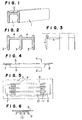
- the reinforcing beam shown in Figure 1 comprises two flanges (1) and one web plate (2).
- the reinforcing beam shown in Figure 2 comprises three flanges (3) and two web plates (4).
- the number of the flanges and the number of the web plates are not critical and the number of the flanges is preferably 7 or less.
- the surfaces of the flanges should be substantially perpendicular to the metallic panel. That is, the surface of the web should be substantially parallel to the metallic panel.
- the web plate should be placed at the position near the metal panel side from the center line of the flanges, that is, the upper side in Figure 3 but the web plate should not be placed at the ends of the flanges.
- the web plate should be arranged in the position of O ⁇ c ⁇ ta. In the consideration of the thickness of the web plate, the distance between the edge of the flange to the surface of the web is not zero. When the edge of the flange is brought into contact with the metallic panel, the surface of the web should not contact with the surface of the metallic panel.
- the web plate should be in the metallic panel side which is the upper side in Figure 3. That is, the surface of the web plate should be substantially parallel to the metallic panel and near the metallic panel.
- the flange surface is usually arranged substantially parallel to the panel. However, it is not preferable to arrange the flange surface parallel to the panel which causes elastic deformation and it is especially not preferable to contact the flange surface with the panel.
- the surface of the web plate is arranged substantially parallel to the panel and should not be easily brought into contact with the metallic panel.
- the latter is one of the reasons for the feature that the surface of the web plate should not be at the edges of the flanges.
- FIGs 4, 5 and 6 show the condition fixing the reinforcing beam on the metallic panel.
- the reinforcing beam (6) is fixed on the metallic panel (5) by two metal joints (7), (8).
- the reinforcing beam (6) comprises the four flanges (9) and the three web plates (10).
- the two joints are fixed on the web plates (10) at both ends of the reinforcing beam (6) by bolts or rivets (11).
- the two joints are welded on the metallic panel.
- the fixing of the reinforcing beam on the metallic panel is preferably carried out by a mechanical fixing of the reinforcing beam to the metallic, joint which is brazed on the metallic panel.
- Figures 7 and 8 show the other system for fixing them.
- the reinforcing beam (12) is fixed on the metallic panel (14) by the metallic joint (13).
- the joint (13) and the reinforcing beam (12) are mechanically fixed by bolts (15) inserted into the flanges of the reinforcing beam.
- the metallic panel (14) is welded to the joint.
- the fixing of the reinforcing beam on the metallic panel is not limited to these manners. It is possible to fix indirectly the reinforcing beam to the metallic panel (See Figure 12) or to fix directly the reinforcing beam to the metallic panel or to fix mechanically the joint to the metallic panel, etc.
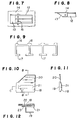
- FIG. 9 shows one embodiment of the improved reinforcing beams.
- One improvement is to have wide width of the edge (16) of the flange at the metallic panel side. This part contacts with the metallic panel and is easily bent. Thus, it is preferable to have wide width.
- the other improvement is to have wide width of the other edge (17) of the flange.
- the strength of the edge (17) can be also increased by increasing the density of the reinforced fiber at this edge part or using a special reinforcing fiber having higher tensile strength than the fiber used in the other reinforced part.
- a reinforcing plate can be inserted adjacent to the fixing part for reinforcing the web of the metallic joint; or the strengthening of the fixing part for fixing the flange and the web plate is increased.
- FIGs 10, 11 and 12 show a door of an automobile on which the reinforcing beam is fixed.
- the door comprises an outer panel (18), an inner panel (19), fixed on the outer panel (18), a window glass (20), and a reinforcing beam (21) arranged on the rear surface of the outer panel (18).
- the reinforcing beam (21) is fixed on the stepped part (23) of the inner panel (19) by the metallic joint (22) by spot welding etc.
- the reinforcing system of the present invention can be applied for the reinforcing of a metallic panel of a door or other outer plates of an automobile or of other parts of an automobile or a metallic panel of other vehicles, buildings etc.
- the FRP used for the reinforcing beam is preferably a fiber reinforced thermosettable resin.
- thermosettable resins include unsaturated polyester resins, epoxy resins, phenolic resins and vinylester resins.
- Suitable reinforcing fibers include inorganic fibers such as glass fiber, carbon fiber, ceramic fiber and organic fibers such as synthetic fibers. It is especially preferable to use glass fiber.
- the reinforcing fiber is preferably orientated in the longitudinal direction of the reinforcing beam. It is especially preferable to orient continuous reinforcing fiber such as glass fiber roving in the longitudinal direction. It is not always necessary to orient all of the reinforcing fibers in the longitudinal direction. In order to give a desired strength to the other direction, the reinforcing fibers which are oriented in the other direction or which are not oriented can be preferably incorporated.
- the reinforcing beam should have the specific sectional configuration. Therefore, it is suitable to fabricate it by a pultrusion method though it is not critical and the reinforcing beam can be also fabricated by a matched die press or the other method.
- the FRP can be a fiber reinforced thermoplastic resin.
- Suitable thermoplastic resins include polyamides, polyolefines, linear polyesters, halogenated vinyl resins, polycarbonates etc.
- the reinforcing fiber can be the organic or inorganic reinforcing fiber.
- the reinforcing fibers are preferably oriented in the longitudinal direction of the reinforcing beam.
- the thermoplastic resin sheet comprising glass fiber roving or chopped strand is fabricated by a stamp molding method etc. to obtain the reinforcing beam.
Landscapes
- Engineering & Computer Science (AREA)
- Mechanical Engineering (AREA)
- Body Structure For Vehicles (AREA)
Claims (6)
Applications Claiming Priority (4)
| Application Number | Priority Date | Filing Date | Title |
|---|---|---|---|
| JP53122738A JPS6027879B2 (ja) | 1978-10-06 | 1978-10-06 | 補強方法 |
| JP122738/78 | 1978-10-06 | ||
| JP15003278A JPS5578893A (en) | 1978-12-06 | 1978-12-06 | Reinforcing beam |
| JP150032/78 | 1978-12-06 |
Publications (2)
| Publication Number | Publication Date |
|---|---|
| EP0010641A1 EP0010641A1 (fr) | 1980-05-14 |
| EP0010641B1 true EP0010641B1 (fr) | 1983-01-26 |
Family
ID=26459809
Family Applications (1)
| Application Number | Title | Priority Date | Filing Date |
|---|---|---|---|
| EP79103803A Expired EP0010641B1 (fr) | 1978-10-06 | 1979-10-04 | Système renforcé par des longerons |
Country Status (3)
| Country | Link |
|---|---|
| US (1) | US4290641A (fr) |
| EP (1) | EP0010641B1 (fr) |
| DE (1) | DE2964626D1 (fr) |
Families Citing this family (12)
| Publication number | Priority date | Publication date | Assignee | Title |
|---|---|---|---|---|
| JPS5688885U (fr) * | 1979-12-10 | 1981-07-16 | ||
| AT375307B (de) * | 1981-04-16 | 1984-07-25 | Vmw Ranshofen Berndorf Ag | Anprallschutzvorrichtung fuer eine einen von einer innenwand und einer aussenwand begrenzten tuerkoerper aufweisende fahrzeugtuer |
| USD283353S (en) | 1983-11-30 | 1986-04-08 | Bancroft Joseph C | Screen spacer extrusion |
| US4684166A (en) * | 1986-05-19 | 1987-08-04 | General Motors Corporation | Vehicle door impact beam and stabilizing assembly |
| AT391453B (de) * | 1986-11-10 | 1990-10-10 | Austria Metall | Profiltraeger, insbesondere rammschutztraeger fuer seitentueren und waende von kraftfahrzeugkarosserien |
| US5095659A (en) * | 1989-05-02 | 1992-03-17 | Atoma International, A Magna International Company | Automobile door modular assembly |
| US4984389A (en) * | 1989-05-02 | 1991-01-15 | Atoma International, A Magna International Company | Automobile door with flush mounted glass |
| DE10153025B4 (de) * | 2001-10-26 | 2007-09-20 | Daimlerchrysler Ag | Aufprallträger einer Fahrzeugkarosserie |
| US6779830B2 (en) * | 2002-04-09 | 2004-08-24 | Ford Global Technologies, Llc | Anti-intrusion beam for a vehicle door assembly |
| DE102005055844B4 (de) | 2005-11-23 | 2023-05-04 | Volkswagen Ag | Aufprallträgeranordnung für eine Fahrzeugtür |
| EP3079951A4 (fr) * | 2013-12-10 | 2017-09-06 | Continental Structural Plastics, Inc. | Barre en i avec revêtement renforcé |
| CA2953651C (fr) * | 2014-06-30 | 2019-02-26 | Nippon Steel & Sumitomo Metal Corporation | Poutrelle de portiere anti-choc |
Family Cites Families (9)
| Publication number | Priority date | Publication date | Assignee | Title |
|---|---|---|---|---|
| DE1959989B1 (de) * | 1969-11-29 | 1971-05-27 | Ford Werke Ag | Seitenschutz fuer Kraftfahrzeuge,bei dem innerhalb der Tueren des Fahrgastraumes jeweils eine Schutzvorrichtung angeordnet ist |
| GB1287160A (en) * | 1969-11-29 | 1972-08-31 | Ford Motor Co | Motor vehicle door |
| US3829149A (en) * | 1973-02-09 | 1974-08-13 | L & L Prod Inc | Beam construction |
| FR2220998A5 (fr) * | 1973-03-06 | 1974-10-04 | Peugeot & Renault | |
| US3868796A (en) * | 1973-04-04 | 1975-03-04 | Ford Motor Co | Side door intrusion protection |
| US4013317A (en) * | 1973-04-16 | 1977-03-22 | Daimler-Benz Aktiengesellschaft | Lateral protection for motor vehicles |
| US3868141A (en) * | 1973-06-15 | 1975-02-25 | Dow Chemical Co | Vehicular safety device |
| DE2426705C2 (de) * | 1974-06-01 | 1985-04-25 | Daimler-Benz Ag, 7000 Stuttgart | Tür für Fahrzeuge, insbesondere für Personenkraftwagen |
| JPS5639698Y2 (fr) * | 1975-10-01 | 1981-09-16 |
-
1979
- 1979-09-26 US US06/079,195 patent/US4290641A/en not_active Expired - Lifetime
- 1979-10-04 EP EP79103803A patent/EP0010641B1/fr not_active Expired
- 1979-10-04 DE DE7979103803T patent/DE2964626D1/de not_active Expired
Also Published As
| Publication number | Publication date |
|---|---|
| DE2964626D1 (en) | 1983-03-03 |
| US4290641A (en) | 1981-09-22 |
| EP0010641A1 (fr) | 1980-05-14 |
Similar Documents
| Publication | Publication Date | Title |
|---|---|---|
| EP0010641B1 (fr) | Système renforcé par des longerons | |
| EP0921055B1 (fr) | Cabine de conducteur d'une machine de chantier | |
| US5033593A (en) | Shock absorbing member for car body | |
| EP1462344B2 (fr) | Carrosserie d'un véhicule automobile avec un élément orienté verticalement | |
| US4488751A (en) | Lateral protection for motor vehicles | |
| EP2006190B1 (fr) | Élément de renforcement pour pied milieu d'un véhicule | |
| EP1113941B1 (fr) | Barre de renforcement de portiere de vehicule et son procede de fabrication | |
| KR100450311B1 (ko) | 차량의 사이드 실 구조 | |
| KR100373987B1 (ko) | 자동차 도어의 임팩트 빔 | |
| KR102521710B1 (ko) | 강 보강부를 갖는 범퍼 빔 | |
| US20020017807A1 (en) | Reinforced front-face support for a motor vehicle | |
| KR19990083007A (ko) | 자동차 도어 충돌 빔 | |
| EP4335729A1 (fr) | Carrosserie de véhicule | |
| US20240097256A1 (en) | Battery case of automobile and method for manufacturing the same | |
| EP0639475A1 (fr) | Poutre de choc pour porte de véhicule et support | |
| JPH06508081A (ja) | 自動車の軽金属ボディのための桁部材 | |
| JPH11208392A (ja) | バンパレインフォースの取付構造 | |
| US4733894A (en) | Energy absorbing vehicle bumper | |
| JP3562795B2 (ja) | 二重構造の側梁による鉄道車両の車体フレーム | |
| EP0710190A1 (fr) | Profile de renforcement | |
| EP0683741B1 (fr) | Sous-ensemble porteur | |
| JPH0617087B2 (ja) | 自動車のドアパネル用補強桁部材 | |
| EP0477727B1 (fr) | Structure de caisse de véhicule | |
| JP2000198401A (ja) | 車両バンパーの補強部材 | |
| CN222202692U (zh) | 车身b柱总成及车辆 |
Legal Events
| Date | Code | Title | Description |
|---|---|---|---|
| PUAI | Public reference made under article 153(3) epc to a published international application that has entered the european phase |
Free format text: ORIGINAL CODE: 0009012 |
|
| AK | Designated contracting states |
Designated state(s): DE FR GB |
|
| 17P | Request for examination filed |
Effective date: 19801027 |
|
| GRAA | (expected) grant |
Free format text: ORIGINAL CODE: 0009210 |
|
| AK | Designated contracting states |
Designated state(s): DE FR GB |
|
| REF | Corresponds to: |
Ref document number: 2964626 Country of ref document: DE Date of ref document: 19830303 |
|
| ET | Fr: translation filed | ||
| PGFP | Annual fee paid to national office [announced via postgrant information from national office to epo] |
Ref country code: FR Payment date: 19911007 Year of fee payment: 13 |
|
| PGFP | Annual fee paid to national office [announced via postgrant information from national office to epo] |
Ref country code: DE Payment date: 19911031 Year of fee payment: 13 |
|
| PGFP | Annual fee paid to national office [announced via postgrant information from national office to epo] |
Ref country code: GB Payment date: 19920922 Year of fee payment: 14 |
|
| PG25 | Lapsed in a contracting state [announced via postgrant information from national office to epo] |
Ref country code: FR Effective date: 19930630 |
|
| PG25 | Lapsed in a contracting state [announced via postgrant information from national office to epo] |
Ref country code: DE Effective date: 19930701 |
|
| REG | Reference to a national code |
Ref country code: FR Ref legal event code: ST |
|
| PG25 | Lapsed in a contracting state [announced via postgrant information from national office to epo] |
Ref country code: GB Effective date: 19931004 |
|
| GBPC | Gb: european patent ceased through non-payment of renewal fee |
Effective date: 19931004 |
|
| PLBE | No opposition filed within time limit |
Free format text: ORIGINAL CODE: 0009261 |
|
| STAA | Information on the status of an ep patent application or granted ep patent |
Free format text: STATUS: NO OPPOSITION FILED WITHIN TIME LIMIT |