EP0010377B1 - Hydraulischer Bremskraftverstärker - Google Patents
Hydraulischer Bremskraftverstärker Download PDFInfo
- Publication number
- EP0010377B1 EP0010377B1 EP19790302092 EP79302092A EP0010377B1 EP 0010377 B1 EP0010377 B1 EP 0010377B1 EP 19790302092 EP19790302092 EP 19790302092 EP 79302092 A EP79302092 A EP 79302092A EP 0010377 B1 EP0010377 B1 EP 0010377B1
- Authority
- EP
- European Patent Office
- Prior art keywords
- piston
- hydraulic booster
- fluid pressure
- booster according
- boost piston
- Prior art date
- Legal status (The legal status is an assumption and is not a legal conclusion. Google has not performed a legal analysis and makes no representation as to the accuracy of the status listed.)
- Expired
Links
- 239000012530 fluid Substances 0.000 claims description 26
- 230000000694 effects Effects 0.000 claims description 5
- 230000003068 static effect Effects 0.000 description 1
Images
Classifications
-
- B—PERFORMING OPERATIONS; TRANSPORTING
- B60—VEHICLES IN GENERAL
- B60T—VEHICLE BRAKE CONTROL SYSTEMS OR PARTS THEREOF; BRAKE CONTROL SYSTEMS OR PARTS THEREOF, IN GENERAL; ARRANGEMENT OF BRAKING ELEMENTS ON VEHICLES IN GENERAL; PORTABLE DEVICES FOR PREVENTING UNWANTED MOVEMENT OF VEHICLES; VEHICLE MODIFICATIONS TO FACILITATE COOLING OF BRAKES
- B60T13/00—Transmitting braking action from initiating means to ultimate brake actuator with power assistance or drive; Brake systems incorporating such transmitting means, e.g. air-pressure brake systems
- B60T13/10—Transmitting braking action from initiating means to ultimate brake actuator with power assistance or drive; Brake systems incorporating such transmitting means, e.g. air-pressure brake systems with fluid assistance, drive, or release
- B60T13/12—Transmitting braking action from initiating means to ultimate brake actuator with power assistance or drive; Brake systems incorporating such transmitting means, e.g. air-pressure brake systems with fluid assistance, drive, or release the fluid being liquid
- B60T13/14—Transmitting braking action from initiating means to ultimate brake actuator with power assistance or drive; Brake systems incorporating such transmitting means, e.g. air-pressure brake systems with fluid assistance, drive, or release the fluid being liquid using accumulators or reservoirs fed by pumps
- B60T13/142—Systems with master cylinder
- B60T13/143—Master cylinder mechanically coupled with booster
- B60T13/144—Pilot valve provided inside booster piston
Definitions
- This invention relates to vehicle fluid pressure brake boosters of the type interposed between a driver's brake pedal and brake applying means so as to reduce the brake pedal load required for a given vehicle braking effect.
- Such fluid boosters include feedback means for developing a brake pedal load substantially proportional to the brake applying force generated by the booster, this provides the vehicle driver with an indication of the braking force developed at the vehicle wheels.
- the feedback means comprise a reslient member interposed between the necessary boost piston and booster output push rod for transferring a fixed proportion of the brake applying force developed by the booster to the brake pedal.
- Other boosters for example as shown in US-A-3 942 326, have feedback means which develop a brake pedal load in accordance with the fluid operating pressure within the booster.
- a hydraulic booster for a vehicle braking system having a fluid pressure power source, the booster having a boost piston, contrll means for governing a differential pressure across the boost piston in accordance with the braking effort required and means arranged so as, in use, to feedback to a brake pedal a load proportional to the brake applying force generated by the booster, characterised thereby that the boost piston has an area arranged to be exposed to fluid pressure from the power source so that, in use, the piston is constantly urged towards a return position by the effect of the fluid pressure on said area.
- the boost piston area arranged to be exposed to fluid pressure is an annulus formed at a radial step in the outside diameter of the boost piston.
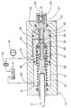
- the apparatus to be described is intended for fitting in a conventional motor vehicle hydraulic brake circuit between a driver's brake pedal and a brake master cylinder.
- a reservoir 11 from which a pump 12 delivers hydraulic fluid under pressure to the inlet port 13 of a brake booster 14.
- An hydraulic accumulator 15 is provided between the pump 12 and the port 13.
- the booster 14 comprises a double diameter closed cylinder whose internal bore 16 houses an annular boost piston 17 for relative axial movement.
- the usual fluid seals 18 are provided between the piston 17 and the bore 16.
- a return spring 19 biases the piston 17 to the rest position, as shown.
- the return spring chamber 21 is connected through a drain port 22 to the fluid reservoir 11.
- the inlet port 13 opens into an annular chamber 24 defined by the step in the bore 16 and in the piston 17.
- An annular boost chamber 25, of larger cross-sectional area than chamber 24, is formed adjacent the end wall 26 of the larger diameter portion of the bore 16.
- a co-axial annular boost piston extension passes through the end wall 26 and houses a socket 27 which receives a thrust rod 28 for connection to an operator's brake pedal (not shown).
- a circlip 29 retains the socket 27 for limited axial movement in a larger diameter end portion of the boost piston bore 31.
- a next smaller diameter portion of the bore 31 houses a control piston 32 which is biased against the socket 27 by a light spring 33 acting betwen the piston 32 and an annular reaction plunger 34 supported in a next larger portion of the bore 31.
- a further largest portion of the bore 31 houses an annular resilient reaction member 35 whose bore is supported by a cylindrical extension of the reaction plunger 34.
- the plunger 34 has limited axial free movement in its piston support bore, as shown.
- a generally dumbell shaped link 36 has one end supported in the largest portion of the bore 31 adjacent the reaction member 35, and the other end supported in an aperture through the end wall of the smaller diameter portion of the bore 16.
- the link 36 houses a push rod 37 for connection to a conventional master cylinder (not shown).
- the return spring 19 acts through the link 36 and reaction member 35 on the boost piston 17.
- the operation of the brake booster valve 14 is as follows:-
- driver's brake pedal causes the socket 27 and the control piston 32 to move inward in the boost piston bore 31, against the effect of the light spring 33, to isolate the boost chamber 25 from the spring chamber 21, and hence the reservoir 11. Further travel of the control piston 32 places the inlet port 13 and the boost chamber 25 in fluid communication.
- control piston 32 is now touching but not loading the reaction plunger 34, neither is the socket 27 directly loading the boost piston 17.
- the boost piston 17 progressively compresses the rim of the reaction member 35 and the piston 17 moves inward relatively to the reaction plunger 34 and control piston 32. Consequently the plunger 34 loads the brake pedal thrust rod 28 through the control piston 32 to resist further travel of the brake pedal, the control piston 32 tending to close communication between the inlet port 13 and the boost chamber 25.
- control piston 32 moves under the action of the light spring 33 to isolate the inlet port 13 and connect the boost chamber 25 through the spring chamber 21 to the reservoir 11
- This booster can be arranged to overcome the master cylinder return spring and brake shoe pull-off springs by increasing the static axial clearance between the control piston 32 and the reaction plunger 34 so that no reaction force is transmitted to the brake pedal until a threshold brake applying force is generated by the booster.
Landscapes
- Engineering & Computer Science (AREA)
- Transportation (AREA)
- Mechanical Engineering (AREA)
- Braking Systems And Boosters (AREA)
Claims (9)
Applications Claiming Priority (2)
| Application Number | Priority Date | Filing Date | Title |
|---|---|---|---|
| GB4104478 | 1978-10-18 | ||
| GB7841044 | 1978-10-18 |
Publications (2)
| Publication Number | Publication Date |
|---|---|
| EP0010377A1 EP0010377A1 (de) | 1980-04-30 |
| EP0010377B1 true EP0010377B1 (de) | 1982-01-06 |
Family
ID=10500420
Family Applications (1)
| Application Number | Title | Priority Date | Filing Date |
|---|---|---|---|
| EP19790302092 Expired EP0010377B1 (de) | 1978-10-18 | 1979-10-03 | Hydraulischer Bremskraftverstärker |
Country Status (4)
| Country | Link |
|---|---|
| EP (1) | EP0010377B1 (de) |
| JP (1) | JPS5555046A (de) |
| AU (1) | AU524915B2 (de) |
| DE (1) | DE2961780D1 (de) |
Families Citing this family (1)
| Publication number | Priority date | Publication date | Assignee | Title |
|---|---|---|---|---|
| GB2104605B (en) * | 1981-07-04 | 1985-03-06 | Lucas Ind Plc | Hydraulic boosters for vehicle braking systems |
Family Cites Families (4)
| Publication number | Priority date | Publication date | Assignee | Title |
|---|---|---|---|---|
| GB1203889A (en) * | 1967-10-30 | 1970-09-03 | Bendix Corp | Improvements in and relating to fluid pressure control valves |
| US3712177A (en) * | 1970-09-21 | 1973-01-23 | Bendix Corp | Hydraulic brake booster with disc reaction |
| JPS5326629B2 (de) * | 1974-03-18 | 1978-08-03 | ||
| GB2003564B (en) * | 1977-09-01 | 1982-02-17 | Girling Ltd | Hydraulic power boosters for vehicle braking systems |
-
1979
- 1979-10-03 DE DE7979302092T patent/DE2961780D1/de not_active Expired
- 1979-10-03 EP EP19790302092 patent/EP0010377B1/de not_active Expired
- 1979-10-04 AU AU51473/79A patent/AU524915B2/en not_active Ceased
- 1979-10-17 JP JP13411279A patent/JPS5555046A/ja active Pending
Also Published As
| Publication number | Publication date |
|---|---|
| AU5147379A (en) | 1980-04-24 |
| JPS5555046A (en) | 1980-04-22 |
| AU524915B2 (en) | 1982-10-07 |
| DE2961780D1 (en) | 1982-02-25 |
| EP0010377A1 (de) | 1980-04-30 |
Similar Documents
| Publication | Publication Date | Title |
|---|---|---|
| US4416491A (en) | Pressure controlling arrangement for use in a vehicle brake system | |
| US5699713A (en) | Brake booster | |
| US3559406A (en) | Vehicle braking system | |
| US3074383A (en) | Full power hydraulic servomotor | |
| US4548037A (en) | Hydraulic power boosters for vehicles braking systems | |
| EP0110740A1 (de) | Bremsbetätigungsaufbau | |
| US3162018A (en) | Split system master cylinder and brake booster | |
| US3613506A (en) | Servomotor having improved no-power operation | |
| US4312182A (en) | Hydraulic control for automobile brakes | |
| US4468927A (en) | Hydraulic boosters for vehicle braking systems | |
| US3106874A (en) | Control valve actuating structure | |
| GB2128279A (en) | Hydraulic brake master cylinder and booster arrangement | |
| US4813338A (en) | Pneumatically operated servo-booster | |
| EP0010377B1 (de) | Hydraulischer Bremskraftverstärker | |
| GB2098687A (en) | A twin master cylinder or booster assembly for a vehicle braking system | |
| US2883970A (en) | Closed system hydraulic motor | |
| US4901626A (en) | Hydraulic power booster | |
| EP0580675B1 (de) | Bremskraftverstaerker | |
| US3706477A (en) | Proportioning device | |
| US4709550A (en) | Hydraulic assistance device | |
| US3709563A (en) | Metering valve assembly for combination valve | |
| US3733106A (en) | Combination valve assembly with proportioner override | |
| EP0065345B1 (de) | Fahrzeugbremsverstärker | |
| US3766735A (en) | Brake booster and master cylinder assembly | |
| US3771316A (en) | Power brake booster with no-power operational features |
Legal Events
| Date | Code | Title | Description |
|---|---|---|---|
| PUAI | Public reference made under article 153(3) epc to a published international application that has entered the european phase |
Free format text: ORIGINAL CODE: 0009012 |
|
| AK | Designated contracting states |
Designated state(s): BE DE FR GB IT SE |
|
| 17P | Request for examination filed | ||
| ITF | It: translation for a ep patent filed | ||
| GRAA | (expected) grant |
Free format text: ORIGINAL CODE: 0009210 |
|
| AK | Designated contracting states |
Designated state(s): BE DE FR GB IT SE |
|
| REF | Corresponds to: |
Ref document number: 2961780 Country of ref document: DE Date of ref document: 19820225 |
|
| RAP2 | Party data changed (patent owner data changed or rights of a patent transferred) |
Owner name: AUTOMOTIVE PRODUCTS PUBLIC LIMITED COMPANY |
|
| PLBI | Opposition filed |
Free format text: ORIGINAL CODE: 0009260 |
|
| PGFP | Annual fee paid to national office [announced via postgrant information from national office to epo] |
Ref country code: FR Payment date: 19820913 Year of fee payment: 4 |
|
| PGFP | Annual fee paid to national office [announced via postgrant information from national office to epo] |
Ref country code: SE Payment date: 19820930 Year of fee payment: 4 Ref country code: BE Payment date: 19820930 Year of fee payment: 4 |
|
| 26 | Opposition filed |
Opponent name: ALFRED TEVES GMBH Effective date: 19820830 |
|
| PGFP | Annual fee paid to national office [announced via postgrant information from national office to epo] |
Ref country code: DE Payment date: 19821231 Year of fee payment: 4 |
|
| RDAG | Patent revoked |
Free format text: ORIGINAL CODE: 0009271 |
|
| STAA | Information on the status of an ep patent application or granted ep patent |
Free format text: STATUS: PATENT REVOKED |
|
| 27W | Patent revoked |
Effective date: 19830520 |
|
| REG | Reference to a national code |
Ref country code: FR Ref legal event code: ST |
|
| EUG | Se: european patent has lapsed |
Ref document number: 79302092.6 Effective date: 19850607 |