EP0010331B1 - Method and means for detecting the location of a marine pipeline or a cable - Google Patents
Method and means for detecting the location of a marine pipeline or a cable Download PDFInfo
- Publication number
- EP0010331B1 EP0010331B1 EP79200583A EP79200583A EP0010331B1 EP 0010331 B1 EP0010331 B1 EP 0010331B1 EP 79200583 A EP79200583 A EP 79200583A EP 79200583 A EP79200583 A EP 79200583A EP 0010331 B1 EP0010331 B1 EP 0010331B1
- Authority
- EP
- European Patent Office
- Prior art keywords
- signals
- colour
- records
- pipeline
- wave
- Prior art date
- Legal status (The legal status is an assumption and is not a legal conclusion. Google has not performed a legal analysis and makes no representation as to the accuracy of the status listed.)
- Expired
Links
- 238000000034 method Methods 0.000 title claims description 16
- 239000003086 colorant Substances 0.000 claims description 19
- XLYOFNOQVPJJNP-UHFFFAOYSA-N water Substances O XLYOFNOQVPJJNP-UHFFFAOYSA-N 0.000 claims description 19
- 238000010420 art technique Methods 0.000 description 3
- 238000001514 detection method Methods 0.000 description 3
- 230000003321 amplification Effects 0.000 description 2
- 238000005259 measurement Methods 0.000 description 2
- 238000003199 nucleic acid amplification method Methods 0.000 description 2
- 230000004913 activation Effects 0.000 description 1
- 230000005540 biological transmission Effects 0.000 description 1
- 239000003990 capacitor Substances 0.000 description 1
- 238000007689 inspection Methods 0.000 description 1
- 238000013507 mapping Methods 0.000 description 1
- 238000009877 rendering Methods 0.000 description 1
- 230000008439 repair process Effects 0.000 description 1
Images


Classifications
-
- G—PHYSICS
- G01—MEASURING; TESTING
- G01V—GEOPHYSICS; GRAVITATIONAL MEASUREMENTS; DETECTING MASSES OR OBJECTS; TAGS
- G01V1/00—Seismology; Seismic or acoustic prospecting or detecting
- G01V1/38—Seismology; Seismic or acoustic prospecting or detecting specially adapted for water-covered areas
- G01V1/3808—Seismic data acquisition, e.g. survey design
-
- G—PHYSICS
- G01—MEASURING; TESTING
- G01S—RADIO DIRECTION-FINDING; RADIO NAVIGATION; DETERMINING DISTANCE OR VELOCITY BY USE OF RADIO WAVES; LOCATING OR PRESENCE-DETECTING BY USE OF THE REFLECTION OR RERADIATION OF RADIO WAVES; ANALOGOUS ARRANGEMENTS USING OTHER WAVES
- G01S15/00—Systems using the reflection or reradiation of acoustic waves, e.g. sonar systems
- G01S15/02—Systems using the reflection or reradiation of acoustic waves, e.g. sonar systems using reflection of acoustic waves
- G01S15/06—Systems determining the position data of a target
-
- G—PHYSICS
- G01—MEASURING; TESTING
- G01S—RADIO DIRECTION-FINDING; RADIO NAVIGATION; DETERMINING DISTANCE OR VELOCITY BY USE OF RADIO WAVES; LOCATING OR PRESENCE-DETECTING BY USE OF THE REFLECTION OR RERADIATION OF RADIO WAVES; ANALOGOUS ARRANGEMENTS USING OTHER WAVES
- G01S15/00—Systems using the reflection or reradiation of acoustic waves, e.g. sonar systems
- G01S15/87—Combinations of sonar systems
-
- G—PHYSICS
- G01—MEASURING; TESTING
- G01S—RADIO DIRECTION-FINDING; RADIO NAVIGATION; DETERMINING DISTANCE OR VELOCITY BY USE OF RADIO WAVES; LOCATING OR PRESENCE-DETECTING BY USE OF THE REFLECTION OR RERADIATION OF RADIO WAVES; ANALOGOUS ARRANGEMENTS USING OTHER WAVES
- G01S7/00—Details of systems according to groups G01S13/00, G01S15/00, G01S17/00
- G01S7/52—Details of systems according to groups G01S13/00, G01S15/00, G01S17/00 of systems according to group G01S15/00
- G01S7/56—Display arrangements
- G01S7/62—Cathode-ray tube displays
- G01S7/6263—Cathode-ray tube displays in which different colours are used
-
- G—PHYSICS
- G01—MEASURING; TESTING
- G01V—GEOPHYSICS; GRAVITATIONAL MEASUREMENTS; DETECTING MASSES OR OBJECTS; TAGS
- G01V1/00—Seismology; Seismic or acoustic prospecting or detecting
- G01V1/28—Processing seismic data, e.g. for interpretation or for event detection
- G01V1/34—Displaying seismic recordings or visualisation of seismic data or attributes
Definitions
- the invention relates to a method for detecting the location of a marine pipeline or a cable by means of a sequence of acoustic wave impulses which are received by a submarine wave receiving means and generated by submarine wave transmitting means and displaying the records in side-by-side relationship in the same sequence as the sequence of the transmitted acoustic pulses from which they originate.
- the invention also relates to a means .for detecting the location of a marine pipeline or a cable by means of a sequence of acoustic wave pulses comprising a receiver for detection of submarine acoustic waves and being adapted to be supported by a vessel below the water level, acoustic wave pulse transmitting means adapted to be supported by the vessel below the water level, means for obtaining a signal as a function of time and representative of the waves received by the receiver, which signals originate from a common wave pulse transmitted by the transmitting means, means for displaying a record of the signals and means for displaying the records in side-by-side- relationship.
- a detection is known from the article "Side Scan Sonar” by Martin Klein in "Offshore Services", April 1977, in particular page 67, fig. 1.
- the wave reflections of the water bottom and the bottom layers often obscure the wave reflections of the pipeline in the display of the records of the signals received by the receiving means, thereby rendering an accurate interpretation of the display impossible.
- the prior art techniques further have no means for indicating at which side of the vessel the pipeline is situated, and to obtain reliable information thereon, the vessel is to be steered at a course that crosses the pipeline at a substantially right angle thereto. It will be appreciated that such crossings that have to be repeated many hundreds of times along the length of the pipeline, are a time consuming operation that renders the prior art techniques economically unattractive.
- Another object of the invention is to provide a means for carrying out this method.
- the method according to the invention is characterized in that the pulses are received by a first and a second submarine wave receiving means situated at substantially equal depth below the water level and in that the submarine wave transmitting means are symmetrically arranged with respect to the plane of symmetry of the first and the second wave receiving means, wherein the wave pulses pass from the transmitting means to the first and second receiving means directly as well as indirectly by being reflected by submarine bottom layers and by the pipeline or the cable, and said method further being characterized by the steps of obtaining after each transmictal of an acoustic pulse a first and a second signal as a function of time of the amplitudes of the acoustic waves received by the first and the second receiving means, respectively, the first and the second signal forming a pair of signals, each signal of a pair of signals including a first part representing the wave pulse reflection(s) by the pipeline or cable, and both signals of a pair further including second parts substantially identical to each other and representing direct wave pulses and wave pulse reflections other than those originally from the pipeline or cable,
- the means according to the invention is characterized by a first and a second receiver for detecting submarine acoustic waves and each being adapted to be supported at equal depth below the water level, acoustic wave pulse transmitting means adapted to be supported below the water level at a location symmetrically arranged with respect to the first .and the second receiver, means for obtaining a first and second signal as a function of time and representative of the waves received by the first and the second wave receiver, respectively, means for combining the signals of each pair of signals, means for displaying a record of the combined signals and identifying in said record the substantially identical parts from the substantially non-identical parts of the signals by separate colours or by various intensities of a single colour.
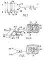
- Figure 8 shows a vertical section over a marine bottom and two transmitting/receiving elements that operate according to a principle that is an alternative of the operation principle of the system shown in Figure 2.
- the pipeline 1 shown in Figure 1 is situated on the seabottom 2 below a body of water 3 on which the surface vessel 4 is floating.
- the vessel 4 tows two paravanes 5 by means of cables 6.
- the paravanes are towed in such a manner by means known per se, that they are substantially symmetrically arranged with respect to the longitudinal plane of symmetry of the vessel 4.
- the paravanes 5 support receivers 8-A and 8-B for receiving acoustic waves, such waves originating from the acoustic pulse transmitter 9 that is supported by the vessel 4 below the waterlevel 7 and is situated in the longitudinal plane of symmetry of the vessel 4.
- the paths of the waves that are received by the receivers 8-A and 8-B after being reflected by the pipeline 1 are indicated by the dash lines 10.
- the acoustic pulses suitable for use in the method according to the invention are high power sound wave pulses of a suitable signal frequency transmitted by the wave transmitting means 9 (see Figure 2).
- Wave transmitting means as well as wave receivers for submarine use are known per se and do not require a detailed description thereof.
- the wave pulses generated by such wave transmitting means travel in spherical expanding wave fronts that either hit the wave receivers 8-A and 8-B (carried by the paravanes 5) directly as indicated by the paths 14, or hit these means indirectly as indicated by the paths 15, 16, 17 and 18 after being reflected by the sea bottom 2, and the reflecting layers 11, 12 and 13 present in the seabottom,
- the receipt of the waves following the paths 14-18, by the receivers 8 is indicated in the records A and B that are schematically shown in Figure 3.
- the record A originates from the waves detected by the receiver 8-A supported by the port paravane 5, whereas the record B originates from the waves detected by the receiver 8-B supported by the starboard paravane 5.
- the relevant arrival times shown on the time axis of the record B are t 15 , t 16' t 17 and t 18' respectively.
- the pipeline 1 is located at port of the vessel 4. Consequently, the path 19 travelled by the wave that is reflected by the pipeline'1 and finally received by the port receiver 8-A is shorter than the path 20 that is followed by the wave that is reflected by the pipeline 1 and finally detected by the starboard receiver 8-B.
- the pipeline reflection signal recorded in record A at time t 19 has arrived earlier than the pipeline reflection signal recorded in record B at time t 2o .
- the difference between these two arrival times indicates that the pipeline is located at port of the vessel.
- the signals at these arrival times are hardly recognizable between the signals that have arrived at times t 15 -t 18 and that result from the reflections of the acoustic pulse by the seabottom and the subsurface reflecting layers.
- the signals reflected by the pipeline are now made distinguishable from the signals formed by the bottom and layer reflections by viewing the record A by an electronic camera 21-A that has the output thereof electrically connected to the input of the red colour gun of a colour cathode ray tube (not shown) as a result whereof record A will be displayed on the screen thereof in red colour.
- the record B is viewed by an electronic camera 21-B that has the output thereof electrically connected to the input of the green colour gun of the colour cathode ray tube, as a result whereof record B will be displayed on the screen in green colour.
- a three-colour record C is formed, wherein the parts that correspond with the substantially identical parts of the records A and B - that are the parts of the records A and B having substantially equal signal strength and pattern and representing direct wave pulses and wave pulse reflections other than those originating from the pipeline - will be presented in yellow colour to the helmsman of the vessel 4, who is watching the screen. It will be appreciated that a yellow colour impression (obtained by mixing the colours red and green) will also.
- the waves reflected by the pipeline 1 and resulting from a single pulse of the transmitting means 9 have, however, arrived at different times at the wave receivers 8-A and 8-B since the paths 19 and 20 differ in length.
- the arrival times t, 9 and t 20 of the signals representing these waves are indicated on the time-axis of the record B and these signals can be identified in the record C by their colours.
- the signal part of record A that has arrived at time t, 9 will be coloured red in the record C, since the camera 21-A is electrically connected to the red colour gun of the cathode ray tube.
- the signal part of record B that has arrived at time t 20 will be coloured green in the record C, since the camera 21-B viewing the record B of which the wave reflection that has arrived at time t 20 forms part, is electrically connected to the green colour gun of the cathode ray tube.
- Figure 4 schematically indicates the hand- ting of the signals to obtain the desired display on the screen of a colour cathode ray tube.
- the wave receivers 8-A and 8-B transduce the acoustic energy of the waves hitting these means into electric energy that is transmitted (after suitable amplification) to the recorder 23 from which a paper sheet 24 is produced on which sheet records are drawn by the movable pens 24-A and 24-B, which records are displayed in a single colour (such as black or any other suitable colour) on the white sheet 23 and are viewed by the electronic cameras 21-A and 21-B, respectively, that have the outputs thereof connected via the electric conduits 25 and 26 to the red colour gun (not shown) and the green colour gun (not shown), respectively of the colour cathode ray tube 27.
- the set of records traced by the pen 24-A is now displayed on the screen 28 of the cathode ray tube 27 simultaneously with the set of records traced by the pen 24-B.
- the last received pair of records is displayed at the bottom of the screen (see record 29). It will be appreciated that each pair of records that originates from a common wave pulse, will be displayed on the screen 28 as a single three-colour record, the three colours are red, green and yellow, this last colour being obtained by mixing red and green. Since the major parts of the records of each pair of records are substantially identical, the dominating colour of the records displayed on the screen will be yellow.
- each combined record representing a pair of records will show a red and a green part.
- red and green parts of the sequences of combined records displayed on the screen 28 will line up, thereby forming a green line 30 and a red line 31. It will be appreciated that over period 32, the pipeline 1 was at port of vessel 4, and the helmsman was steering to port until at the moment between the periods 32 and 33 the vessel 4 was exactly above the pipeline 1.
- the pipeline was at starboard of the vessel and the vessel was being steered to have the lines 30 and 31 as closely together, in order that the vessel would follow the pipeline without undesired deviations from the track thereof.
- Any desired measurements may be carried out over the period that the vessel follows the pipeline track, such as for measuring the depth at which the pipeline is buried below the sea bottom by receiving the reflections of the wave pulses by a receiving means that is mounted close to the wave pulse transmitting means 9, or forms part of said latter means.
- a piezoelectric element can be used for this purpose, which is controlled in a known manner by an electric circuit that periodically supplies electric energy to the element for transmitting purposes, and periodically switches the element to another circuit adapted for measuring any loads exerted on the element by acoustic wave hitting the element.
- the data originating from the receivers 8-A and 8-B are (after suitable amplification) supplied to a processor 35 (see Figure 5) which has the output thereof coupled to the input of a monitor 36.
- the data are temporarily stored in the processor 35 (or in a minicomputer suitable for the purpose) and are periodically transmitted - after being amplified to a suitable degree - to the monitor 36, in such a way that the data of the most recent pair of signals A and B are combined to display a three-colour record on the lowermost line of the monitor 36, whereas each preceding pair of signals A and B is combined to form a three-colour record that is displayed on a higher line of a monitor, in the sequence in which the relevant pairs of signals have been received by the receivers 8-A and 8-B.
- Each subsequent receipt of a new pair of signals A, B is displayed on the lowermost line of the monitor in the form of a three-colour record, and the preceding records are all shifted one line to the top of the monitor, thereby deleting the oldest trace that was displayed on the uppermost line of the monitor 36.
- the dominant colour of the records displayed on the monitor will be yellow if the red and green colour guns of the monitor are commanded to display the data originating from the receivers 8-A and 8-B, respectively.
- the red and green parts shown by each three-colour record will (provided that the vessel is not right above the pipeline) line up in the display on the monitor to red and green lines 37 and 38, respectively.
- FIG. 6 of the drawings shows schematically a way of displaying combined pairs of signals originating from the receivers 8-A and 8-B, wherein instead of a three-coloured display of the combined data, a single colour display is used with various intensities.
- a grey shade recorder is used for this purpose which recorder produces traces having various grey shades in dependence on the voltage applied to the input thereof.
- Such grey shade- (graphic-, facsimilie-) recorders are known per se and will therefore not be described here in detail.
- the signals received by the receivers 8-A and 8-B are separately passed through envelope detectors 40-A and 40-B, respectively.
- the basic scheme of such envelope detector is shown in Figure 7.
- the circuit of such a detector consists of a diode 41, a capacitor 42 and a resistor 43 that are electrically interconnected in the manner shown.
- the signals After having passed through the envelope detectors, the signals are added with opposite sign, whereafter a positive direct voltage P.V. of a pre-determined constant value is added. This voltage represents the background grey level.
- the signals are then supplied to the input 44 of the grey-shade recorder 45. It will be appreciated that the voltages representing the substantially identical parts of the signals form- 'ing a pair and originating from the receivers 8-A and 8-B will substantially cancel each other in the signal supplied to the recorder, as a result whereof these parts-will obtain the background grey level in the display of the recorder 45.
- the wave pulse reflection by the pipeline and detected by receiver 8-A will, however, not be cancelled if the vessel is not right above the pipeline, and the signal supplied to the recorder 45 will then have a voltage of a level that is higher than the level of the voltage P.V. representing the background grey level. Consequently, that part of the recorded signal will have a darker shade of grey, which may even turn to black in case of a very strong reflection of the wave pulse by the pipeline. Further, the signal representing the wave-pulse reflection received by receiver 8-B will, lower the voltage P.V. supplied to the input of the recorder, as a result whereof that part of the recorded signal will have a lighter shade of grey, which may even turn to white in case of a very strong reflection of the wave pulse of the pipeline.
- FIG. 8 of the drawings shows an embodiment of the invention comprising an alternative arrangement of transmitting and receiving means.
- These means consist of combined acoustic wave transmitting and receiving elements, such as the piezoelectric element referred to hereinabove.
- Two of these elements 50, 51 are symmetrically arranged with respect to the longitudinal plane of symmetry 52 of a (not shown) vessel.
- Figure 8 shows a cross-section of the body of water on which the vessel is floating, this section being taken rectangular to said plane of symmetry.
- the elements 50, 51 are located at equal depths below the water level 53 and are supported by the vessel (not shown) either directly by the hull thereof, or indirectly by paravanes that are towed thereby.
- Activation of the elements 50, 51 to transmit a wave pulse takes place simultaneously and periodically. After each wave pulse transmission, each of the elements 50, 51 is connected to a circuit adapted for measuring the receipt of acoustic waves that hit the said elements.
- Lines 59-62 indicate the paths travelled in two directions by acoustic waves originating from the piezoelectric element 50 and reflected by the seabottom 55 and the layers 56-58, respectively.
- the reflected energy of these waves will be received by the element 50 at substantially the same strength and at substantially the same time as the reflected energy of the waves that have travelled along the paths indicated by the lines 63-66, which waves have been generated and received by the element 51, and been reflected by the seabottom 55 and the reflecting layers 56-58. Therefore, when combining the records after having identified them by a first and a second colour, respectively, those parts of the combined records formed of the signals re- received by the elements 50, 51 that result from waves that have travelled along vertical paths and have been reflected by the seabottom 55 and the layers 56-58 will be represented by a third colour that is obtained by mixing of the first and the second colour.
- Such representation by the third colour also takes place for the waves that have travelled directly from the element 50 to the element 51 along the path indicated by the line 67, and from the element 51 to the element 50 along the path indicated by the line 68, as well as for the waves travelling in both directions along the paths indicated by the lines 69-72, which waves are reflected in the plane of symmetry 52 by the seabottom 55 and the layers 56, 57 and 58.
- the waves emitted by the piezoelectric element 50 and received by the piezoelectric element 51 after having been reflected by the pipeline 54 will have the same distance of travel (see the path indicated by the line 73) as the waves reflected by the pipeline but traveling from the element 51 to the element 50. It will be appreciated that the signals appearing in a combined record and resulting from these reflected waves will also be represented by the third colour.
- the records A and B may be displayed in a two-colour print, which forms the trace C wherein three colours can be distinguished, to wit the original two colours, and a third colour resulting from mixing the other two colours.
- This third colour indicates the substantially identical parts of the basic records, which parts do not contain any useful data on the position of the vessel with respect to the pipeline.
- the invention is not limited to the application of a surface vessel for supporting the wave transmitting and receiving means. Submarines may be used for this purpose as well. Also, the invention is not limited to the use of paravanes. If desired, the wave transmitting means and/or the wave receiving means may be carried directly by the vessel, such as by being mounted on the hull thereof, or on booms or other supporting means that are connected to the hull.
- more than one set of pipetracing equipment according to the invention may be used on a single vessel. Such is in particular attractive when the vessel is of great length, and should be positioned above the vessel over the total length thereof, as may be required when carrying out pipeline repairs from such vessel.
Landscapes
- Engineering & Computer Science (AREA)
- Remote Sensing (AREA)
- Physics & Mathematics (AREA)
- Radar, Positioning & Navigation (AREA)
- Life Sciences & Earth Sciences (AREA)
- General Physics & Mathematics (AREA)
- Acoustics & Sound (AREA)
- Computer Networks & Wireless Communication (AREA)
- Geology (AREA)
- General Life Sciences & Earth Sciences (AREA)
- Environmental & Geological Engineering (AREA)
- Geophysics (AREA)
- Oceanography (AREA)
- Measurement Of Velocity Or Position Using Acoustic Or Ultrasonic Waves (AREA)
- Geophysics And Detection Of Objects (AREA)
- Laying Of Electric Cables Or Lines Outside (AREA)
Description
- The invention relates to a method for detecting the location of a marine pipeline or a cable by means of a sequence of acoustic wave impulses which are received by a submarine wave receiving means and generated by submarine wave transmitting means and displaying the records in side-by-side relationship in the same sequence as the sequence of the transmitted acoustic pulses from which they originate.
- The invention also relates to a means .for detecting the location of a marine pipeline or a cable by means of a sequence of acoustic wave pulses comprising a receiver for detection of submarine acoustic waves and being adapted to be supported by a vessel below the water level, acoustic wave pulse transmitting means adapted to be supported by the vessel below the water level, means for obtaining a signal as a function of time and representative of the waves received by the receiver, which signals originate from a common wave pulse transmitted by the transmitting means, means for displaying a record of the signals and means for displaying the records in side-by-side- relationship. Such a detection is known from the article "Side Scan Sonar" by Martin Klein in "Offshore Services", April 1977, in
particular page 67, fig. 1. - Numerous pipelines (and cables) have already been placed during the last decades on and in the bottom of seas and oceans, which pipelines have to be inspected from time to time, such as for checking the depth at which they are located below the sea or ocean bottom. Such inspection is carried out by vessels, such as surface vessels and submarines carrying equipment for detecting the presence of the pipeline (or cable) on or in the marine bottom for mapping the actual position thereof and at the same time taking other measurements in relation to the pipeline. As described in the above-mentioned article in "Offshore Services" pipeline detection is usually carried out by generating a sequence of acoustic wave pulses by submarine wave transmitting means. Acoustic waves reflected by the pipeline are detected by submarine wave receiving means and displayed to show the position of the pipeline or cable with respect to the water bottom.
- In the prior art techniques, the wave reflections of the water bottom and the bottom layers, however, often obscure the wave reflections of the pipeline in the display of the records of the signals received by the receiving means, thereby rendering an accurate interpretation of the display impossible. The prior art techniques further have no means for indicating at which side of the vessel the pipeline is situated, and to obtain reliable information thereon, the vessel is to be steered at a course that crosses the pipeline at a substantially right angle thereto. It will be appreciated that such crossings that have to be repeated many hundreds of times along the length of the pipeline, are a time consuming operation that renders the prior art techniques economically unattractive.
- Therefore, it is an object of the invention to provide a method for detecting a submarine pipeline or a cable wherein the position of the vessel with respect to the pipeline or cable can be ascertained and at the same time the undesired acoustic pulse reflections originating from the marine bottom layers, as well as the wave pulses directly received by the receiving means are suppressed to such an extent that the errors in reading the display are minimized.
- Another object of the invention is to provide a means for carrying out this method.
- The method according to the invention is characterized in that the pulses are received by a first and a second submarine wave receiving means situated at substantially equal depth below the water level and in that the submarine wave transmitting means are symmetrically arranged with respect to the plane of symmetry of the first and the second wave receiving means, wherein the wave pulses pass from the transmitting means to the first and second receiving means directly as well as indirectly by being reflected by submarine bottom layers and by the pipeline or the cable, and said method further being characterized by the steps of obtaining after each transmictal of an acoustic pulse a first and a second signal as a function of time of the amplitudes of the acoustic waves received by the first and the second receiving means, respectively, the first and the second signal forming a pair of signals, each signal of a pair of signals including a first part representing the wave pulse reflection(s) by the pipeline or cable, and both signals of a pair further including second parts substantially identical to each other and representing direct wave pulses and wave pulse reflections other than those originally from the pipeline or cable, combining the signals of each pair and displaying a record of the combined signals, identifying in the record of the combined signals the first parts from each other as well as from the substantially identical second parts by separate colours or by various intensities of a single colour when the pipeline or cable is outside the plane of symmetry.
- Further, the means according to the invention is characterized by a first and a second receiver for detecting submarine acoustic waves and each being adapted to be supported at equal depth below the water level, acoustic wave pulse transmitting means adapted to be supported below the water level at a location symmetrically arranged with respect to the first .and the second receiver, means for obtaining a first and second signal as a function of time and representative of the waves received by the first and the second wave receiver, respectively, means for combining the signals of each pair of signals, means for displaying a record of the combined signals and identifying in said record the substantially identical parts from the substantially non-identical parts of the signals by separate colours or by various intensities of a single colour.
- It can further be remarked that from U.S.-A-4,005,383 a side scan sonar technique is known, which is used as a navigation system in crowded harbours, narrow channels and other restricted water. However, this U.S. patent has nothing whatever to do with the techniques of pipeline tracking, as does the present invention as set out in the appended claims to which reference should now be made.
- The invention will be described hereinafter in more detail with reference to the drawings wherein some embodiments of the invention are shown by way of example.
- Figure 1 shows schematically in perspective view a surface vessel passing as closely as possible over and along a pipeline situated on the bottom of a body of water.
- Figure 2 shows schematically on a larger scale the vertical section II-II of Figure 1.
- Figure 3 shows schematically the records A and B of acoustic waves records received by the wave receiving means of the means according to the invention, as well as record C that is formed by combining the records A and B.
- Figure 4 shows schematically equipment according to the invention wherein use is made of three different colours for identifying the position of a vessel with respect to a submarine pipeline.
- Figure 5 shows schematically other equipment according to the invention wherein use- is made of three different colours for identifying the position of a vessel with respect to a submarine pipeline.
- Figure 6 shows schematically equipment according to the invention wherein use is made of various intensities of a single colour for identifying the position of a vessel with respect to a: submarine pipeline.
- Figure 7 shows schematically an electric circuit of an envelope detector for use in the equipment of Figure 6.
- Finally, Figure 8 shows a vertical section over a marine bottom and two transmitting/receiving elements that operate according to a principle that is an alternative of the operation principle of the system shown in Figure 2.
- The pipeline 1 shown in Figure 1 is situated on the seabottom 2 below a body of
water 3 on which the surface vessel 4 is floating. The vessel 4 tows twoparavanes 5 by means ofcables 6. The paravanes are towed in such a manner by means known per se, that they are substantially symmetrically arranged with respect to the longitudinal plane of symmetry of the vessel 4. Theparavanes 5 support receivers 8-A and 8-B for receiving acoustic waves, such waves originating from theacoustic pulse transmitter 9 that is supported by the vessel 4 below thewaterlevel 7 and is situated in the longitudinal plane of symmetry of the vessel 4. The paths of the waves that are received by the receivers 8-A and 8-B after being reflected by the pipeline 1 are indicated by thedash lines 10. - However, there are also waves that reach the
wave receiving means 8 along other paths. These latter waves travel from the transmitting means 9 through the body of water to thereceivers 8 either directly or indirectly after having been reflected by the sea-bottom 2 and/or thesubsurface layers - The acoustic pulses suitable for use in the method according to the invention are high power sound wave pulses of a suitable signal frequency transmitted by the wave transmitting means 9 (see Figure 2). Wave transmitting means as well as wave receivers for submarine use are known per se and do not require a detailed description thereof. The wave pulses generated by such wave transmitting means travel in spherical expanding wave fronts that either hit the wave receivers 8-A and 8-B (carried by the paravanes 5) directly as indicated by the paths 14, or hit these means indirectly as indicated by the
paths layers - - It will. be appreciated that both paths'14 are of substantially equal length since the wave transmitting
means 9 is located in the plane of symmetry of the wave receivers 8-A and 8-B. The same applies, since thereflecting surfaces paths 15, bothpaths 16, bothpaths 17, as well as bothpaths 18. Such is further also the case for- any other pair of paths followed by waves that have been reflected by any other reflecting layers that are present below the sea bottom 2, and that have not been shown in the drawing. - The receipt of the waves following the paths 14-18, by the
receivers 8 is indicated in the records A and B that are schematically shown in Figure 3. The record A originates from the waves detected by the receiver 8-A supported by theport paravane 5, whereas the record B originates from the waves detected by the receiver 8-B supported by thestarboard paravane 5. - Time to indicates the moment at which an acoustic wave pulse is transmitted by the transmitting
means 9, and it will be appreciated that the arrival of the direct waves travelling along the paths 14 will be at exactly the same moment by the port and the starboard receiver 8-A and 8-B, respectively, at the time t14 indicated on the time axis of the record B. The same applies for the waves that have been reflected by the sea bottom 2 and by the reflectinglayers - As shown in Figure 2, the pipeline 1 is located at port of the vessel 4. Consequently, the
path 19 travelled by the wave that is reflected by the pipeline'1 and finally received by the port receiver 8-A is shorter than thepath 20 that is followed by the wave that is reflected by the pipeline 1 and finally detected by the starboard receiver 8-B. Thus, the pipeline reflection signal recorded in record A at time t19 has arrived earlier than the pipeline reflection signal recorded in record B at time t2o. The difference between these two arrival times indicates that the pipeline is located at port of the vessel. However, the signals at these arrival times are hardly recognizable between the signals that have arrived at times t15-t18 and that result from the reflections of the acoustic pulse by the seabottom and the subsurface reflecting layers. The signals reflected by the pipeline are now made distinguishable from the signals formed by the bottom and layer reflections by viewing the record A by an electronic camera 21-A that has the output thereof electrically connected to the input of the red colour gun of a colour cathode ray tube (not shown) as a result whereof record A will be displayed on the screen thereof in red colour. The record B is viewed by an electronic camera 21-B that has the output thereof electrically connected to the input of the green colour gun of the colour cathode ray tube, as a result whereof record B will be displayed on the screen in green colour. - By displaying the pair of records A (in red colour) and B (in green colour) simultaneously such that the time-axes thereof coincide (with coinciding times to), a three-colour record C is formed, wherein the parts that correspond with the substantially identical parts of the records A and B - that are the parts of the records A and B having substantially equal signal strength and pattern and representing direct wave pulses and wave pulse reflections other than those originating from the pipeline - will be presented in yellow colour to the helmsman of the vessel 4, who is watching the screen. It will be appreciated that a yellow colour impression (obtained by mixing the colours red and green) will also. be given to the helmsman, if the signals of these substantially identical parts are not exactly equal in strength, and/or there are small differences in arrival time, which latter a.o. may be due to a small tilt of the relevant reflecting layer and/or a small difference in the submergence of the
paravanes 5. The yellow parts of the record C are indicated in dashlines in Figure 3. - The waves reflected by the pipeline 1 and resulting from a single pulse of the transmitting
means 9 have, however, arrived at different times at the wave receivers 8-A and 8-B since thepaths - A way of presenting the information on the lengths of the
paths - Figure 4 schematically indicates the hand- ting of the signals to obtain the desired display on the screen of a colour cathode ray tube. The wave receivers 8-A and 8-B transduce the acoustic energy of the waves hitting these means into electric energy that is transmitted (after suitable amplification) to the
recorder 23 from which apaper sheet 24 is produced on which sheet records are drawn by the movable pens 24-A and 24-B, which records are displayed in a single colour (such as black or any other suitable colour) on thewhite sheet 23 and are viewed by the electronic cameras 21-A and 21-B, respectively, that have the outputs thereof connected via theelectric conduits cathode ray tube 27. - The set of records traced by the pen 24-A is now displayed on the
screen 28 of thecathode ray tube 27 simultaneously with the set of records traced by the pen 24-B. The last received pair of records is displayed at the bottom of the screen (see record 29). It will be appreciated that each pair of records that originates from a common wave pulse, will be displayed on thescreen 28 as a single three-colour record, the three colours are red, green and yellow, this last colour being obtained by mixing red and green. Since the major parts of the records of each pair of records are substantially identical, the dominating colour of the records displayed on the screen will be yellow. If the vessel is not exactly right above the pipeline that is being surveyed (or in other words if the pipeline is not located in the plane of symmetry of the receivers 8-A and 8-B) each combined record representing a pair of records will show a red and a green part. These red and green parts of the sequences of combined records displayed on thescreen 28 will line up, thereby forming agreen line 30 and ared line 31. It will be appreciated that over period 32, the pipeline 1 was at port of vessel 4, and the helmsman was steering to port until at the moment between the periods 32 and 33 the vessel 4 was exactly above the pipeline 1. Thereafter (over the period 33) the pipeline was at starboard of the vessel and the vessel was being steered to have thelines - In an alternative manner, the data originating from the receivers 8-A and 8-B are (after suitable amplification) supplied to a processor 35 (see Figure 5) which has the output thereof coupled to the input of a
monitor 36. The data are temporarily stored in the processor 35 (or in a minicomputer suitable for the purpose) and are periodically transmitted - after being amplified to a suitable degree - to themonitor 36, in such a way that the data of the most recent pair of signals A and B are combined to display a three-colour record on the lowermost line of themonitor 36, whereas each preceding pair of signals A and B is combined to form a three-colour record that is displayed on a higher line of a monitor, in the sequence in which the relevant pairs of signals have been received by the receivers 8-A and 8-B. Each subsequent receipt of a new pair of signals A, B is displayed on the lowermost line of the monitor in the form of a three-colour record, and the preceding records are all shifted one line to the top of the monitor, thereby deleting the oldest trace that was displayed on the uppermost line of themonitor 36. As has been explained already with reference to Figure 4, the dominant colour of the records displayed on the monitor will be yellow if the red and green colour guns of the monitor are commanded to display the data originating from the receivers 8-A and 8-B, respectively. The red and green parts shown by each three-colour record will (provided that the vessel is not right above the pipeline) line up in the display on the monitor to red andgreen lines - Reference is now made to Figure 6 of the drawings, which figure shows schematically a way of displaying combined pairs of signals originating from the receivers 8-A and 8-B, wherein instead of a three-coloured display of the combined data, a single colour display is used with various intensities. A grey shade recorder is used for this purpose which recorder produces traces having various grey shades in dependence on the voltage applied to the input thereof. Such grey shade- (graphic-, facsimilie-) recorders are known per se and will therefore not be described here in detail.
- The signals received by the receivers 8-A and 8-B are separately passed through envelope detectors 40-A and 40-B, respectively. The basic scheme of such envelope detector is shown in Figure 7. The circuit of such a detector consists of a
diode 41, a capacitor 42 and aresistor 43 that are electrically interconnected in the manner shown. - After having passed through the envelope detectors, the signals are added with opposite sign, whereafter a positive direct voltage P.V. of a pre-determined constant value is added. This voltage represents the background grey level. The signals are then supplied to the
input 44 of the grey-shade recorder 45. It will be appreciated that the voltages representing the substantially identical parts of the signals form- 'ing a pair and originating from the receivers 8-A and 8-B will substantially cancel each other in the signal supplied to the recorder, as a result whereof these parts-will obtain the background grey level in the display of therecorder 45. - The wave pulse reflection by the pipeline and detected by receiver 8-A will, however, not be cancelled if the vessel is not right above the pipeline, and the signal supplied to the
recorder 45 will then have a voltage of a level that is higher than the level of the voltage P.V. representing the background grey level. Consequently, that part of the recorded signal will have a darker shade of grey, which may even turn to black in case of a very strong reflection of the wave pulse by the pipeline. Further, the signal representing the wave-pulse reflection received by receiver 8-B will, lower the voltage P.V. supplied to the input of the recorder, as a result whereof that part of the recorded signal will have a lighter shade of grey, which may even turn to white in case of a very strong reflection of the wave pulse of the pipeline. The darker shades of grey and the lighter shades of grey in the sequence of records recorded by the grey-shade recorder 45 will line up, thereby forminglines lines - Finally, reference is made to Figure 8 of the drawings, which figure shows an embodiment of the invention comprising an alternative arrangement of transmitting and receiving means. These means consist of combined acoustic wave transmitting and receiving elements, such as the piezoelectric element referred to hereinabove. Two of these
elements symmetry 52 of a (not shown) vessel. Figure 8 shows a cross-section of the body of water on which the vessel is floating, this section being taken rectangular to said plane of symmetry. Theelements water level 53 and are supported by the vessel (not shown) either directly by the hull thereof, or indirectly by paravanes that are towed thereby. Activation of theelements elements - The
pipeline 54 that is buried below the sea-bottom 55 is shown in cross-section in Figure 8. - In the sea bottom, there are
layers - Lines 59-62 indicate the paths travelled in two directions by acoustic waves originating from the
piezoelectric element 50 and reflected by the seabottom 55 and the layers 56-58, respectively. - It will be appreciated that the reflected energy of these waves will be received by the
element 50 at substantially the same strength and at substantially the same time as the reflected energy of the waves that have travelled along the paths indicated by the lines 63-66, which waves have been generated and received by theelement 51, and been reflected by the seabottom 55 and the reflecting layers 56-58. Therefore, when combining the records after having identified them by a first and a second colour, respectively, those parts of the combined records formed of the signals re- received by theelements - Such representation by the third colour also takes place for the waves that have travelled directly from the
element 50 to theelement 51 along the path indicated by theline 67, and from theelement 51 to theelement 50 along the path indicated by theline 68, as well as for the waves travelling in both directions along the paths indicated by the lines 69-72, which waves are reflected in the plane ofsymmetry 52 by the seabottom 55 and thelayers - Further, the waves emitted by the
piezoelectric element 50 and received by thepiezoelectric element 51 after having been reflected by thepipeline 54 will have the same distance of travel (see the path indicated by the line 73) as the waves reflected by the pipeline but traveling from theelement 51 to theelement 50. It will be appreciated that the signals appearing in a combined record and resulting from these reflected waves will also be represented by the third colour. - Those wave portions that originate from the
element 50 and after reflection by thepipeline 54 are returned to this element for receipt thereby will, however, be represented by the first colour. The path followed by these wave portions is indicated by theline 74. Further, a path indicated by theline 75 will be followed by wave portions originating from theelement 51 and returned to this element after being reflected by thepipeline 54. As long as the central axis of thepipeline 54 is outside the plane ofsymmetry 52, the paths indicated by thelines elements elements - Application of the method of the present invention using the three-colour principle is not limited to the use of a colour cathode ray tube for displaying the position of the vessel with respect to the pipeline. In an alternative form, the records A and B (of Figure 3) may be displayed in a two-colour print, which forms the trace C wherein three colours can be distinguished, to wit the original two colours, and a third colour resulting from mixing the other two colours. This third colour indicates the substantially identical parts of the basic records, which parts do not contain any useful data on the position of the vessel with respect to the pipeline.
- It will be appreciated that the lengths of the paths indicated by the
lines pipeline 54 is in the plane ofsymetry 52 of theelements elements paths symmetry 52 of theelements - Further, the invention is not limited to the application of a surface vessel for supporting the wave transmitting and receiving means. Submarines may be used for this purpose as well. Also, the invention is not limited to the use of paravanes. If desired, the wave transmitting means and/or the wave receiving means may be carried directly by the vessel, such as by being mounted on the hull thereof, or on booms or other supporting means that are connected to the hull.
- Apart from the colours red and green that have been used in some of examples of the embodiments of the invention as described herein, other pairs of colours may be used as well, provided that these colours, as well as the colour obtained by mixing these colours are easily identifiable by the human eye.
- Further, more than one set of pipetracing equipment according to the invention may be used on a single vessel. Such is in particular attractive when the vessel is of great length, and should be positioned above the vessel over the total length thereof, as may be required when carrying out pipeline repairs from such vessel.
Claims (15)
Applications Claiming Priority (2)
| Application Number | Priority Date | Filing Date | Title |
|---|---|---|---|
| GB7841648A GB2032104B (en) | 1978-10-23 | 1978-10-23 | Marine pipeline or cable location |
| GB4164878 | 1978-10-23 |
Publications (2)
| Publication Number | Publication Date |
|---|---|
| EP0010331A1 EP0010331A1 (en) | 1980-04-30 |
| EP0010331B1 true EP0010331B1 (en) | 1982-05-19 |
Family
ID=10500531
Family Applications (1)
| Application Number | Title | Priority Date | Filing Date |
|---|---|---|---|
| EP79200583A Expired EP0010331B1 (en) | 1978-10-23 | 1979-10-12 | Method and means for detecting the location of a marine pipeline or a cable |
Country Status (9)
| Country | Link |
|---|---|
| US (1) | US4247923A (en) |
| EP (1) | EP0010331B1 (en) |
| JP (1) | JPS5559363A (en) |
| AU (1) | AU524072B2 (en) |
| CA (1) | CA1136256A (en) |
| DE (1) | DE2962908D1 (en) |
| DK (1) | DK440979A (en) |
| GB (1) | GB2032104B (en) |
| NO (1) | NO149445C (en) |
Cited By (1)
| Publication number | Priority date | Publication date | Assignee | Title |
|---|---|---|---|---|
| EP3898404A1 (en) * | 2018-12-20 | 2021-10-27 | ATLAS ELEKTRONIK GmbH | Arrangement and method for locating an object in or below a body of water |
Families Citing this family (23)
| Publication number | Priority date | Publication date | Assignee | Title |
|---|---|---|---|---|
| US4467461A (en) * | 1981-01-05 | 1984-08-21 | Conoco Inc. | Interactive color analysis of geophysical data |
| US4406242A (en) * | 1981-03-11 | 1983-09-27 | Weeks Colin G | Oceanographic sensor system |
| US4446538A (en) * | 1982-03-16 | 1984-05-01 | Mobil Oil Corporation | Marine cable location system |
| US4513401A (en) * | 1982-03-16 | 1985-04-23 | Mobil Oil Corporation | Marine cable location system |
| DE3221013A1 (en) * | 1982-06-04 | 1983-12-08 | Fried. Krupp Gmbh, 4300 Essen | METHOD FOR UNDERWATER LOCATION WITH SOUND IMPULSES, IN PARTICULAR FOR DETECTION AND / OR CLASSIFICATION ON OR CLOSE TO THE BASE OF WATER, AND DEVICE FOR IMPLEMENTING THE METHOD |
| FR2532437B1 (en) * | 1982-08-31 | 1985-12-27 | Commissariat Energie Atomique | ULTRASONIC DEVICE FOR LOCATING AN OBJECT |
| JPS60231190A (en) * | 1984-05-01 | 1985-11-16 | Koden Electronics Co Ltd | Echo detector |
| US4975887A (en) * | 1987-01-09 | 1990-12-04 | The United States Of America As Represented By The Secretary Of The Navy | Bistatic side scan sonar |
| KR950005359B1 (en) * | 1991-03-25 | 1995-05-23 | 마쓰다 가부시끼가이샤 | Powertrain for an automotive vehicle |
| US5537366A (en) * | 1995-07-03 | 1996-07-16 | Northrop Grumman | Buried cable pipe detection sonar |
| GB0013719D0 (en) * | 2000-06-07 | 2000-07-26 | Coflexip | Subsea pipeline touchdown monitoring |
| FR2818388B1 (en) | 2000-12-15 | 2003-02-14 | Inst Francais Du Petrole | METHOD AND DEVICE FOR SEISMIC EXPLORATION OF AN UNDERGROUND SUBTERRANEAN AREA, USING SEISMIC RECEPTORS COUPLED WITH THE BOTTOM OF WATER |
| CA2588047A1 (en) * | 2004-08-02 | 2006-02-16 | Johnson Outdoors Inc. | Sonar imaging system for mounting to watercraft |
| US8305840B2 (en) | 2009-07-14 | 2012-11-06 | Navico, Inc. | Downscan imaging sonar |
| US8300499B2 (en) | 2009-07-14 | 2012-10-30 | Navico, Inc. | Linear and circular downscan imaging sonar |
| US9142206B2 (en) | 2011-07-14 | 2015-09-22 | Navico Holding As | System for interchangeable mounting options for a sonar transducer |
| US9268020B2 (en) | 2012-02-10 | 2016-02-23 | Navico Holding As | Sonar assembly for reduced interference |
| US9354312B2 (en) | 2012-07-06 | 2016-05-31 | Navico Holding As | Sonar system using frequency bursts |
| US10495460B2 (en) * | 2015-03-09 | 2019-12-03 | Saipem S.P.A. | Detection system and method to check the position of a pipeline in a bed of a body of water |
| US11367425B2 (en) | 2017-09-21 | 2022-06-21 | Navico Holding As | Sonar transducer with multiple mounting options |
| DE102018201251A1 (en) | 2018-01-26 | 2019-08-01 | Fugro N.V. | Detecting objects that are submerged in a body of water or at least partially hidden in a body of water |
| NO348074B1 (en) | 2021-05-20 | 2024-07-15 | Argeo Robotics As | Adaptive steering of AUV |
| CN114563783B (en) * | 2022-04-26 | 2022-08-05 | 苏州光格科技股份有限公司 | Submarine cable route detection system and method |
Family Cites Families (17)
| Publication number | Priority date | Publication date | Assignee | Title |
|---|---|---|---|---|
| GB490322A (en) * | 1937-05-25 | 1938-08-12 | Basil Scruby | Improved method and apparatus for detecting sound sources |
| DE951075C (en) * | 1950-09-26 | 1956-10-18 | Electroacustic Ges M B H | Method and device for displaying reflective objects using the echo pulse method |
| DE916631C (en) * | 1951-07-17 | 1954-08-12 | Atlas Werke Ag | Device for displaying objects using the echo method |
| DE1203477B (en) * | 1956-11-17 | 1965-10-21 | Dr Siegfried Fahrentholz | Registering echo sounder device for surveying waterways |
| US4005383A (en) * | 1960-02-12 | 1977-01-25 | The United States Of America As Represented By The Secretary Of The Navy | Catacoustic navigating system |
| NL267037A (en) * | 1960-07-13 | |||
| DE1272560C2 (en) * | 1962-01-11 | 1969-02-20 | Phil Nat Siegfried Fahrentholz | Echosounder device for surveying waterways |
| DE1516622B2 (en) * | 1965-02-16 | 1971-07-22 | Electroacustic Gmbh, 2300 Kiel | SOUNDER PROCEDURE ACCORDING TO THE SUM DIFFERENCE PRINCIPLE AND EQUIPMENT TO EXERCISE IT |
| US3271512A (en) * | 1965-10-12 | 1966-09-06 | Polaroid Corp | Color television method and apparatus employing different sets of target phosphors, one of which luminesces in a single color and another of which luminesces in different colors |
| US3443023A (en) * | 1966-02-07 | 1969-05-06 | Polaroid Corp | Two-color line-sequential color television |
| DE1506161C3 (en) * | 1967-02-08 | 1974-10-03 | Fried. Krupp Gmbh, 4300 Essen | Arrangement for measuring waters by means of the echo sounder method |
| US3652793A (en) * | 1968-03-29 | 1972-03-28 | Muirhead Ltd | Facsimile apparatus having plural reciprocating scanning heads |
| BE757456A (en) * | 1969-10-17 | 1971-03-16 | Westinghouse Electric Corp | SIDE VIEW SONAR DEVICE |
| US3614720A (en) * | 1969-11-13 | 1971-10-19 | Us Navy | Logarithmic three-color display sonar |
| US3744013A (en) * | 1972-01-20 | 1973-07-03 | Edo Western Corp | Method for searching a medium |
| JPS5175552A (en) * | 1974-12-26 | 1976-06-30 | Koden Electronics Co Ltd | TAJUSUICHUCHOONPATANCHIKI |
| US4025895A (en) * | 1975-09-18 | 1977-05-24 | Sante Fe International Corporation | Navigation system for maneuvering a structure about a submerged object |
-
1978
- 1978-10-23 GB GB7841648A patent/GB2032104B/en not_active Expired
-
1979
- 1979-05-25 US US06/042,398 patent/US4247923A/en not_active Expired - Lifetime
- 1979-07-31 CA CA000332903A patent/CA1136256A/en not_active Expired
- 1979-10-12 DE DE7979200583T patent/DE2962908D1/en not_active Expired
- 1979-10-12 EP EP79200583A patent/EP0010331B1/en not_active Expired
- 1979-10-19 NO NO793372A patent/NO149445C/en unknown
- 1979-10-19 DK DK440979A patent/DK440979A/en not_active Application Discontinuation
- 1979-10-19 JP JP13429379A patent/JPS5559363A/en active Pending
- 1979-10-19 AU AU51978/79A patent/AU524072B2/en not_active Ceased
Cited By (1)
| Publication number | Priority date | Publication date | Assignee | Title |
|---|---|---|---|---|
| EP3898404A1 (en) * | 2018-12-20 | 2021-10-27 | ATLAS ELEKTRONIK GmbH | Arrangement and method for locating an object in or below a body of water |
Also Published As
| Publication number | Publication date |
|---|---|
| JPS5559363A (en) | 1980-05-02 |
| NO149445B (en) | 1984-01-09 |
| CA1136256A (en) | 1982-11-23 |
| EP0010331A1 (en) | 1980-04-30 |
| DE2962908D1 (en) | 1982-07-08 |
| US4247923A (en) | 1981-01-27 |
| DK440979A (en) | 1980-04-24 |
| NO793372L (en) | 1980-04-24 |
| GB2032104B (en) | 1983-02-02 |
| GB2032104A (en) | 1980-04-30 |
| NO149445C (en) | 1984-04-25 |
| AU524072B2 (en) | 1982-08-26 |
| AU5197879A (en) | 1980-05-01 |
Similar Documents
| Publication | Publication Date | Title |
|---|---|---|
| EP0010331B1 (en) | Method and means for detecting the location of a marine pipeline or a cable | |
| Grant et al. | Modern swathe sounding and sub-bottom profiling technology for research applications: the Atlas Hydrosweep and Parasound systems | |
| US4862422A (en) | Method for determining the geometry of a multisource seismic wave emission device | |
| US4216537A (en) | Sonar for the topographic representation of a submerged surface and underlying strata | |
| US6873570B2 (en) | High resolution bathymetric sonar system and measuring method for measuring the physiognomy of the seabed | |
| US4648080A (en) | Method for determining the far field signature of a marine seismic source from near-field measurements | |
| US4658384A (en) | Method for determining the far-field signature of an air gun array | |
| EP0624253B1 (en) | Feature location and display apparatus | |
| CA1195762A (en) | Submerged marine streamer locator | |
| US4845686A (en) | Method and device for determining the position of immersed objects with respect to the ship which tows them | |
| EP0516662B1 (en) | Electrooptical sensor system for marine seismic data acquisition | |
| US7366056B2 (en) | Depth sounding by acoustic pingers in a seismic spread | |
| US4709356A (en) | Seismic array positioning | |
| USRE31026E (en) | Navigation system for maneuvering a structure about a submerged object | |
| JPS61142488A (en) | Marine probing method by utilizing one or more of remote control ship | |
| US4025895A (en) | Navigation system for maneuvering a structure about a submerged object | |
| JPH1020045A (en) | Undersea exploration equipment | |
| Leenhardt | Side scanning sonar-a theoretical study | |
| Koyama et al. | Bathymetry by new designed interferometry sonar mounted on AUV | |
| Bjørnø | Developments in sonar technologies and their applications | |
| RU2229226C1 (en) | Fish finder | |
| GB2083219A (en) | Sonar system | |
| Bidgood | A deep towed sea bottom profiling system | |
| EP4339652A1 (en) | Negative offset interleaved high resolution system for seismic surveys | |
| Tyler et al. | Geophysical Techniques for Offshore Site Investigation |
Legal Events
| Date | Code | Title | Description |
|---|---|---|---|
| PUAI | Public reference made under article 153(3) epc to a published international application that has entered the european phase |
Free format text: ORIGINAL CODE: 0009012 |
|
| AK | Designated contracting states |
Designated state(s): DE FR IT NL |
|
| 17P | Request for examination filed | ||
| ITF | It: translation for a ep patent filed | ||
| GRAA | (expected) grant |
Free format text: ORIGINAL CODE: 0009210 |
|
| AK | Designated contracting states |
Designated state(s): DE FR IT NL |
|
| REF | Corresponds to: |
Ref document number: 2962908 Country of ref document: DE Date of ref document: 19820708 |
|
| PGFP | Annual fee paid to national office [announced via postgrant information from national office to epo] |
Ref country code: FR Payment date: 19840820 Year of fee payment: 6 |
|
| PGFP | Annual fee paid to national office [announced via postgrant information from national office to epo] |
Ref country code: DE Payment date: 19841115 Year of fee payment: 6 |
|
| PGFP | Annual fee paid to national office [announced via postgrant information from national office to epo] |
Ref country code: NL Payment date: 19861031 Year of fee payment: 8 |
|
| PG25 | Lapsed in a contracting state [announced via postgrant information from national office to epo] |
Ref country code: NL Effective date: 19880501 |
|
| NLV4 | Nl: lapsed or anulled due to non-payment of the annual fee | ||
| PG25 | Lapsed in a contracting state [announced via postgrant information from national office to epo] |
Ref country code: FR Free format text: LAPSE BECAUSE OF NON-PAYMENT OF DUE FEES Effective date: 19880630 |
|
| PG25 | Lapsed in a contracting state [announced via postgrant information from national office to epo] |
Ref country code: DE Effective date: 19880701 |
|
| REG | Reference to a national code |
Ref country code: FR Ref legal event code: ST |
|
| PLBE | No opposition filed within time limit |
Free format text: ORIGINAL CODE: 0009261 |
|
| STAA | Information on the status of an ep patent application or granted ep patent |
Free format text: STATUS: NO OPPOSITION FILED WITHIN TIME LIMIT |