EP0010261B2 - Vertikaler Wasserdampf-Abscheider-Überhitzer - Google Patents
Vertikaler Wasserdampf-Abscheider-Überhitzer Download PDFInfo
- Publication number
- EP0010261B2 EP0010261B2 EP79103904A EP79103904A EP0010261B2 EP 0010261 B2 EP0010261 B2 EP 0010261B2 EP 79103904 A EP79103904 A EP 79103904A EP 79103904 A EP79103904 A EP 79103904A EP 0010261 B2 EP0010261 B2 EP 0010261B2
- Authority
- EP
- European Patent Office
- Prior art keywords
- separator
- pyramid
- annular
- superheater
- zone
- Prior art date
- Legal status (The legal status is an assumption and is not a legal conclusion. Google has not performed a legal analysis and makes no representation as to the accuracy of the status listed.)
- Expired
Links
Images

Classifications
-
- F—MECHANICAL ENGINEERING; LIGHTING; HEATING; WEAPONS; BLASTING
- F22—STEAM GENERATION
- F22B—METHODS OF STEAM GENERATION; STEAM BOILERS
- F22B37/00—Component parts or details of steam boilers
- F22B37/02—Component parts or details of steam boilers applicable to more than one kind or type of steam boiler
- F22B37/26—Steam-separating arrangements
- F22B37/266—Separator reheaters
Definitions
- the present invention relates to a vertical steam separator-superheater, comprising inside a common ferrule a lower part forming a separation zone comprising an annular chamber for the admission of wet steam, connected to openings for introducing this last, and separating elements grouped in stacks separated by at least one gap connected to the annular inlet chamber and of width decreasing from bottom to top, and an upper part forming an overheating zone, comprising an axial zone of arrival of dry steam, tubular bundles of overheating arranged in envelopes distributed around the central zone, and fixed to a thin and flexible ferrule itself fixed to the upper part of the common ferrule, and a peripheral zone for collecting superheated steam .
- a separator-superheater of this kind makes it possible to absorb the expansions and contractions of the superheater bundles without special device such as expansion lyres, and facilitates the possible extraction of these bundles in view of their repair.
- the arrangement of the separator elements grouped in several parallel rows of V-shaped stacks makes it less easy to access the internal walls of the lower zone of the separator-superheater, and it also imposes the orientation of the access pipes. wet steam to be treated, since this must arrive symmetrically with respect to the rows of stacks of separating elements.
- the object of the present invention is to provide a separator-superheater which allows excellent accessibility to all the internal walls of the lower zone ensuring the separation function, and whose access pipes of the steam to be treated can have any orientation. It also aims to provide a set of separating elements in which the bodies for discharging the stopped water occupy a very small place.
- the separator-superheater according to the present invention is characterized in that the separator elements are grouped in two truncated coaxial pyramids, the external pyramid having its large base at a level lower than that of its small base, and the internal pyramid its large base at a level higher than that of its small base, and the annular chamber being connected by an annular passage to the volume internal to the external pyramid, but external to the internal pyramid.
- Flow devices for the water stopped in the separating elements are arranged at the edges of the truncated pyramids.
- Part of the annular passage is formed by the internal wall of the bottom of the common ferrule.
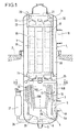
- the separator-superheater of FIG. 1 comprises, inside a cylindrical shell 1, supported by a usual annular support by a floor 2, a lower part 3 (forming a separator) and an upper part 4 (forming a superheater) .
- the lower part is fitted with 4A pipes for supplying wet steam.
- 4A pipes for supplying wet steam.
- Part of the internal wall of this passage is formed by the wall 6A of the bottom of the shell. This reduces the total height of the separating part 3, but requires that the wall 6A be coated with stainless steel, like the rest of the passage wall, in order to avoid the phenomenon of erosion-corrosion by wet steam. at high speed.
- the other part of the external wall of the passage consists of sheets 7 angularly offset with respect to the vertical axis and separated by interstices 7A at stepped levels, ensuring a preliminary separation of the water droplets under the effect of the centrifugal force resulting from the change in direction of the vapor.
- the water separated on the sheets 7 and flowing through the interstices 7A collects in the bottom 8 with the water retained in the separating elements, as will be indicated below, and is discharged through the axial tube 9.
- the separating elements are grouped in two truncated pyramids with an octagonal base, the external pyramid 10 having its large base downwards, and the internal pyramid 11 with its large base upwards, the latter being substantially in contact with the small base of the external pyramid. It therefore appears between the two pyramids an annular gap 12, of decreasing width upwards, for the access of the wet steam to the separating elements.
- the pyramids of separating elements are provided along their external edges with elements for discharging separate water, such as 13A for the external pyramid and 13B for the internal pyramid.
- the dried steam leaving the separating elements meets on the one hand, in an axial zone 14A, on the other hand in a peripheral zone 14B.
- the assembly then rises through an intermediate zone 13 towards the upper overheating part 4.
- This overheating part is similar to that described in the intermediate document FR-A 2406157 and will therefore not be described in detail again. It comprises an axial zone 15, around which are arranged four superheater bundles such as 16, 17. These are fixed to the internal surface of a thin shell 30, itself welded by its upper edge to the upper bottom 31 of the ferrule. The dried steam therefore rises towards the axial zone 15, then radially crosses the bundles while overheating and reaches an outlet pipe 19 through a peripheral zone 18 for collecting the superheated steam.
- the superheater bundles are supplied with high pressure steam via the pipe 20, the O-manifold 21 and the connections 22 connected to the end chambers 23.
- the high pressure steam condensed mainly in the tubular bundles such as 16, 17 and arriving in the end chambers 24, are collected in the collector 25, then sent via the conduit 26 to the recipe pot 27.
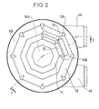
- FIG. 2 shows more precisely the arrangement of the separate water collection members, such as 13A, 13B, respectively at the edges of the outer and inner pyramids of the stacks of separating elements, therefore in the blind spots between the rectangular separators , only two of which have been represented.
- This arrangement allows the useful volume offered to be reduced only to a small extent, while ensuring satisfactory flow of the separated water.
- separator 32 of the external truncated pyramid and a separator 33 of the internal truncated pyramid. It can also be seen that the separator system is symmetrical with respect to the vertical axis of the shell.
- FIG. 3 represents a separator-superheater similar to that of FIGS. 1 and 2, but in which the passage 6 of the wet steam from the inlet pipes to the separating elements is more distant from the bottom of the shell.
- the identical members will therefore not be described again.
- the passage 6 always prints a 180 ° bend with wet steam, which allows a preliminary separation of the water droplets on the sheets 7 delimiting the passage, with evacuation of the water by the interstices 7A between these sheets.
- the number of sides of the truncated pyramids formed by the stacks of separators can be less than or greater than eight. It is possible to provide for a partial withdrawal of dried steam before it is introduced into the overheating zone.
Landscapes
- Engineering & Computer Science (AREA)
- Physics & Mathematics (AREA)
- Thermal Sciences (AREA)
- Mechanical Engineering (AREA)
- General Engineering & Computer Science (AREA)
- Separating Particles In Gases By Inertia (AREA)
- Cyclones (AREA)
- Drying Of Solid Materials (AREA)
Claims (5)
Applications Claiming Priority (2)
| Application Number | Priority Date | Filing Date | Title |
|---|---|---|---|
| FR7829673 | 1978-10-18 | ||
| FR7829673A FR2439358A2 (fr) | 1978-10-18 | 1978-10-18 | Separateur-surchauffeur de vapeur vertical |
Publications (3)
| Publication Number | Publication Date |
|---|---|
| EP0010261A1 EP0010261A1 (de) | 1980-04-30 |
| EP0010261B1 EP0010261B1 (de) | 1982-05-19 |
| EP0010261B2 true EP0010261B2 (de) | 1985-04-10 |
Family
ID=9213895
Family Applications (1)
| Application Number | Title | Priority Date | Filing Date |
|---|---|---|---|
| EP79103904A Expired EP0010261B2 (de) | 1978-10-18 | 1979-10-11 | Vertikaler Wasserdampf-Abscheider-Überhitzer |
Country Status (6)
| Country | Link |
|---|---|
| US (1) | US4273077A (de) |
| EP (1) | EP0010261B2 (de) |
| CA (1) | CA1118651A (de) |
| DE (1) | DE2941825A1 (de) |
| ES (1) | ES485103A2 (de) |
| FR (1) | FR2439358A2 (de) |
Families Citing this family (5)
| Publication number | Priority date | Publication date | Assignee | Title |
|---|---|---|---|---|
| DE3307101C2 (de) * | 1983-03-01 | 1985-09-26 | L. & C. Steinmüller GmbH, 5270 Gummersbach | Aus Blechpaketen bestehender Wasserabscheider zum Trocknen von Naßdampf mit anschließender Überhitzung des getrockneten Dampfes |
| DE3531054C1 (de) * | 1985-08-30 | 1986-11-06 | L. & C. Steinmüller GmbH, 5270 Gummersbach | Vorrichtung zum Trocknen von Nassdampf und anschliessendem UEberhitzen des getrockneten Dampfes |
| CN103216817A (zh) * | 2013-01-30 | 2013-07-24 | 珠海新市节能环保科技有限公司 | 一种用于锅炉的汽水隔离器 |
| CA3047873C (en) * | 2016-09-30 | 2022-06-07 | Public Joint Stock Company "Machine-Building Plant "Zio-Podolsk" | Steam superheater |
| CN109966806B (zh) * | 2017-12-28 | 2024-04-09 | 核动力运行研究所 | 一种基于立式汽水分离再热器的预分离器 |
Family Cites Families (7)
| Publication number | Priority date | Publication date | Assignee | Title |
|---|---|---|---|---|
| DE2128897C3 (de) * | 1971-06-11 | 1978-11-23 | L. & C. Steinmueller Gmbh, 5270 Gummersbach | Vorrichtung zum Abscheiden von in einem Gasstrom enthaltener Flüssigkeit |
| FR2187394B1 (de) * | 1972-06-15 | 1974-12-27 | Stein Industrie | |
| US3867908A (en) * | 1973-04-24 | 1975-02-25 | Westinghouse Electric Corp | Cross flow baffle for a steam generator |
| DE2555539A1 (de) * | 1975-12-10 | 1977-06-23 | Steinmueller Gmbh L & C | Vorrichtung zum trocknen von nassdampf und anschliessendem ueberhitzen des getrockneten dampfes |
| US4068627A (en) * | 1976-01-06 | 1978-01-17 | Westinghouse Electric Corporation | Steam generator with vertical tubesheets |
| DE2703024C3 (de) * | 1977-01-26 | 1979-06-28 | L. & C. Steinmueller Gmbh, 5270 Gummersbach | Vorrichtung zum Trocknen von Naßdampf und anschließendem Oberhitzen des getrockneten Dampfes |
| FR2406157A1 (fr) * | 1977-10-17 | 1979-05-11 | Stein Industrie | Separateur-surchauffeur de vapeur vertical |
-
1978
- 1978-10-18 FR FR7829673A patent/FR2439358A2/fr active Granted
-
1979
- 1979-10-11 EP EP79103904A patent/EP0010261B2/de not_active Expired
- 1979-10-15 US US06/084,709 patent/US4273077A/en not_active Expired - Lifetime
- 1979-10-16 DE DE19792941825 patent/DE2941825A1/de not_active Withdrawn
- 1979-10-16 CA CA000337870A patent/CA1118651A/fr not_active Expired
- 1979-10-17 ES ES485103A patent/ES485103A2/es not_active Expired
Also Published As
| Publication number | Publication date |
|---|---|
| US4273077A (en) | 1981-06-16 |
| ES485103A2 (es) | 1980-07-01 |
| EP0010261B1 (de) | 1982-05-19 |
| CA1118651A (fr) | 1982-02-23 |
| FR2439358A2 (fr) | 1980-05-16 |
| DE2941825A1 (de) | 1980-04-30 |
| FR2439358B2 (de) | 1982-03-05 |
| EP0010261A1 (de) | 1980-04-30 |
Similar Documents
| Publication | Publication Date | Title |
|---|---|---|
| FR2460720A1 (fr) | Separateur de sable pour la preparation de pate cellulosique | |
| EP0010261B2 (de) | Vertikaler Wasserdampf-Abscheider-Überhitzer | |
| EP0005494B1 (de) | Vertikal-Abscheider eines Gemisches von Dampf oder Gas mit flüssigen oder festen Teilchen | |
| FR2462655A1 (fr) | Distributeur collecteur de boues pour generateur nucleaire de vapeur | |
| EP0763384B1 (de) | Zentrifugalabschneider, insbesondere für einen Kessel mit zirkulierendem Wirbelbett | |
| FR2460701A1 (fr) | Dispositif de separation de matieres solides dans un courant de liquide | |
| FR2558741A1 (fr) | Separateur de melanges par centrifugation | |
| BE879140R (fr) | Separateur-surchauffeur de vapeur vertical | |
| EP0068958A1 (de) | Dampferzeuger mit einem dynamischen Dampfwasserableiter | |
| EP1704289A1 (de) | Flüssigkeitsevakuierungsvorrichtung und entsprechende flüssigkeitsführungsvorrichtung | |
| CH386215A (fr) | Procédé et appareil pour l'épuration de gaz chargés de particules solides | |
| FR2924486A1 (fr) | Systeme double collecteur de boue et de corps etrangers pour generateur de vapeur | |
| BE502624A (de) | ||
| FR2899824A1 (fr) | Separateur centrifuge pour la separation de liquide a partir d'un flux de gaz | |
| EP0032088B1 (de) | Vorrichtung zum Trennen von Flüssigkeit und Dampf aus einem Fluid-Strom und Dampferzeuger mit solchen Vorrichtungen | |
| EP0202967B1 (de) | Speisewasservorwärmer für Dampferzeuger | |
| EP0626536A1 (de) | Dampferzeuger ausgerüstet mit einem Fremdpartikelfilter | |
| EP0002235B1 (de) | Senkrechter Abscheider für eine Dampfflüssigkeitsmischung | |
| EP0285124B1 (de) | Speisewasserentgaser für Dampferzeuger | |
| EP0043760A1 (de) | Dampftrockneranlage für Dampferzeuger, insbesondere für Kernreaktor-Dampferzeuger | |
| EP0566477B1 (de) | Dampferzeuger mit einer Wasserablenkungvorrichtung und einer Schlammentleerungsbahn | |
| FR2602697A1 (fr) | Bol centrifuge pour clarifier ou separer des liquides a centrifuger | |
| EP0568434B1 (de) | Vorrichtung zur Abgabe und Verteilung von Speise- und Rezirkulationswasser in der Sekundärseite eines Dampferzeugers | |
| BE552171A (de) | ||
| EP0558386B1 (de) | Verbesserte Vorrichtung zur Kristallisation durch Verdampfung |
Legal Events
| Date | Code | Title | Description |
|---|---|---|---|
| PUAI | Public reference made under article 153(3) epc to a published international application that has entered the european phase |
Free format text: ORIGINAL CODE: 0009012 |
|
| AK | Designated contracting states |
Designated state(s): CH FR GB IT SE |
|
| 17P | Request for examination filed | ||
| ITF | It: translation for a ep patent filed | ||
| GRAA | (expected) grant |
Free format text: ORIGINAL CODE: 0009210 |
|
| AK | Designated contracting states |
Designated state(s): CH FR GB IT SE |
|
| PLBI | Opposition filed |
Free format text: ORIGINAL CODE: 0009260 |
|
| 26 | Opposition filed |
Opponent name: KRAFTWERK UNION AKTIENGESELLSCHAFT Effective date: 19830221 Opponent name: DEUTSCHE BABCOCK AKTIENGESELLSCHAFT Effective date: 19830218 |
|
| PGFP | Annual fee paid to national office [announced via postgrant information from national office to epo] |
Ref country code: FR Payment date: 19840322 Year of fee payment: 6 |
|
| PGFP | Annual fee paid to national office [announced via postgrant information from national office to epo] |
Ref country code: CH Payment date: 19840813 Year of fee payment: 6 |
|
| PGFP | Annual fee paid to national office [announced via postgrant information from national office to epo] |
Ref country code: SE Payment date: 19840930 Year of fee payment: 6 |
|
| ITF | It: translation for a ep patent filed | ||
| PUAH | Patent maintained in amended form |
Free format text: ORIGINAL CODE: 0009272 |
|
| STAA | Information on the status of an ep patent application or granted ep patent |
Free format text: STATUS: PATENT MAINTAINED AS AMENDED |
|
| 27A | Patent maintained in amended form | ||
| AK | Designated contracting states |
Kind code of ref document: B2 Designated state(s): CH FR GB IT SE |
|
| PG25 | Lapsed in a contracting state [announced via postgrant information from national office to epo] |
Ref country code: GB Effective date: 19881011 |
|
| PG25 | Lapsed in a contracting state [announced via postgrant information from national office to epo] |
Ref country code: SE Effective date: 19881012 |
|
| PG25 | Lapsed in a contracting state [announced via postgrant information from national office to epo] |
Ref country code: CH Effective date: 19881031 |
|
| PG25 | Lapsed in a contracting state [announced via postgrant information from national office to epo] |
Ref country code: FR Free format text: LAPSE BECAUSE OF NON-PAYMENT OF DUE FEES Effective date: 19890630 |
|
| REG | Reference to a national code |
Ref country code: CH Ref legal event code: PL |
|
| GBPC | Gb: european patent ceased through non-payment of renewal fee | ||
| REG | Reference to a national code |
Ref country code: FR Ref legal event code: ST |
|
| EUG | Se: european patent has lapsed |
Ref document number: 79103904.3 Effective date: 19890614 |
|
| PLAB | Opposition data, opponent's data or that of the opponent's representative modified |
Free format text: ORIGINAL CODE: 0009299OPPO |