EP0010253B1 - Continuous distillation apparatus and method of operation - Google Patents
Continuous distillation apparatus and method of operation Download PDFInfo
- Publication number
- EP0010253B1 EP0010253B1 EP79103872A EP79103872A EP0010253B1 EP 0010253 B1 EP0010253 B1 EP 0010253B1 EP 79103872 A EP79103872 A EP 79103872A EP 79103872 A EP79103872 A EP 79103872A EP 0010253 B1 EP0010253 B1 EP 0010253B1
- Authority
- EP
- European Patent Office
- Prior art keywords
- section
- vapor
- liquid
- stripping section
- rectifying
- Prior art date
- Legal status (The legal status is an assumption and is not a legal conclusion. Google has not performed a legal analysis and makes no representation as to the accuracy of the status listed.)
- Expired
Links
Images
Classifications
-
- B—PERFORMING OPERATIONS; TRANSPORTING
- B01—PHYSICAL OR CHEMICAL PROCESSES OR APPARATUS IN GENERAL
- B01D—SEPARATION
- B01D3/00—Distillation or related exchange processes in which liquids are contacted with gaseous media, e.g. stripping
- B01D3/14—Fractional distillation or use of a fractionation or rectification column
- B01D3/16—Fractionating columns in which vapour bubbles through liquid
- B01D3/166—Heating and/or cooling of plates
-
- B—PERFORMING OPERATIONS; TRANSPORTING
- B01—PHYSICAL OR CHEMICAL PROCESSES OR APPARATUS IN GENERAL
- B01D—SEPARATION
- B01D3/00—Distillation or related exchange processes in which liquids are contacted with gaseous media, e.g. stripping
- B01D3/14—Fractional distillation or use of a fractionation or rectification column
- B01D3/141—Fractional distillation or use of a fractionation or rectification column where at least one distillation column contains at least one dividing wall
-
- B—PERFORMING OPERATIONS; TRANSPORTING
- B01—PHYSICAL OR CHEMICAL PROCESSES OR APPARATUS IN GENERAL
- B01D—SEPARATION
- B01D3/00—Distillation or related exchange processes in which liquids are contacted with gaseous media, e.g. stripping
- B01D3/14—Fractional distillation or use of a fractionation or rectification column
- B01D3/143—Fractional distillation or use of a fractionation or rectification column by two or more of a fractionation, separation or rectification step
-
- B—PERFORMING OPERATIONS; TRANSPORTING
- B01—PHYSICAL OR CHEMICAL PROCESSES OR APPARATUS IN GENERAL
- B01D—SEPARATION
- B01D3/00—Distillation or related exchange processes in which liquids are contacted with gaseous media, e.g. stripping
- B01D3/14—Fractional distillation or use of a fractionation or rectification column
- B01D3/16—Fractionating columns in which vapour bubbles through liquid
-
- Y—GENERAL TAGGING OF NEW TECHNOLOGICAL DEVELOPMENTS; GENERAL TAGGING OF CROSS-SECTIONAL TECHNOLOGIES SPANNING OVER SEVERAL SECTIONS OF THE IPC; TECHNICAL SUBJECTS COVERED BY FORMER USPC CROSS-REFERENCE ART COLLECTIONS [XRACs] AND DIGESTS
- Y10—TECHNICAL SUBJECTS COVERED BY FORMER USPC
- Y10S—TECHNICAL SUBJECTS COVERED BY FORMER USPC CROSS-REFERENCE ART COLLECTIONS [XRACs] AND DIGESTS
- Y10S203/00—Distillation: processes, separatory
- Y10S203/04—Heat pump
-
- Y—GENERAL TAGGING OF NEW TECHNOLOGICAL DEVELOPMENTS; GENERAL TAGGING OF CROSS-SECTIONAL TECHNOLOGIES SPANNING OVER SEVERAL SECTIONS OF THE IPC; TECHNICAL SUBJECTS COVERED BY FORMER USPC CROSS-REFERENCE ART COLLECTIONS [XRACs] AND DIGESTS
- Y10—TECHNICAL SUBJECTS COVERED BY FORMER USPC
- Y10S—TECHNICAL SUBJECTS COVERED BY FORMER USPC CROSS-REFERENCE ART COLLECTIONS [XRACs] AND DIGESTS
- Y10S203/00—Distillation: processes, separatory
- Y10S203/11—Batch distillation
-
- Y—GENERAL TAGGING OF NEW TECHNOLOGICAL DEVELOPMENTS; GENERAL TAGGING OF CROSS-SECTIONAL TECHNOLOGIES SPANNING OVER SEVERAL SECTIONS OF THE IPC; TECHNICAL SUBJECTS COVERED BY FORMER USPC CROSS-REFERENCE ART COLLECTIONS [XRACs] AND DIGESTS
- Y10—TECHNICAL SUBJECTS COVERED BY FORMER USPC
- Y10S—TECHNICAL SUBJECTS COVERED BY FORMER USPC CROSS-REFERENCE ART COLLECTIONS [XRACs] AND DIGESTS
- Y10S62/00—Refrigeration
- Y10S62/902—Apparatus
- Y10S62/905—Column
Definitions
- This invention relates to a continuous distillation apparatus and method of operation thereof, comprising a vertical column containing a stripping section and a rectifying section.
- Distillation is the single most important separation unit operation in the process industry. It is widely used to upgrade feed stocks, separate reaction intermediates, and purify products in processes ranging from cryogenic separation of oxygen, nitrogen, and helium to the recovery of aromatics from coal.
- distillation was determined to be an important energy consumer in almost every refinery and chemical plant.
- crude and vacuum distillation alone accounts for between 22.5 and 51% of the total energy consumed. Accordingly, any enhancement of the energy balance for a distillation unit operation will have a significant impact on a wide cross section of the process industry.
- FIG. 1 a typical, prior art, continuous distillation or fractionating column equipped with the necessary auxiliary equipment and containing rectifying and stripping sections is shown.
- the column A is fed near its center with a feed of definite concentration.
- the feed is assumed to be a liquid at or near its boiling point.
- the plate on which the feed enters is called the feed plate. All plates above the feed plate constitute the rectifying section, and all plates below the feed, including the feed plate itself, constitute the stripping section.
- the liquid in the feed flows down the stripping section to the bottom of the column where a definite liquid level is maintained.
- Liquid is removed from the stripping section and flows by gravity to reboiler B that generates vapor and returns the vapor to the bottom of the stripping section portion of the column.
- the reboiler may be of the kettle (as shown), thermosyphon, forced circulation, etc., type.
- the bottom product may undergo-further processing or may flow (as shown) through a cooler H which also preheats the feed by heat exchange therewith.
- Vapor from reboiler B passes up the entire column through both the stripping and rectifying sections and is removed from the column and partially or totally condensed in a condenser C.
- the condensate is collected in an accumulator D from which reflux pump F removes liquid and delivers it to the top plate of the rectifying section.
- This liquid stream is called reflux and provides the down-flowing liquid in the rectifying section necessary to act on the upflowing vapor.
- Reflux liquid provides the required rectification since no rectification would occur in the rectifying section without the reflux. Without rectification the concentration of the overhead product would be no greater than in the vapor rising from the feed plate.
- Condensate from accumulator D that is not picked up by the reflux pump F is withdrawn as overhead product and may be cooled in a heat exchanger E, called the product cooler. If no azeotropes are encountered, both overhead and bottom products may be obtained in any desired purity if enough plates and adequate reflux are provided.
- thermal energy is removed from the vapor in condenser C at a lower temperature than the thermal energy introduced into reboiler B. Accordingly, in the absence of any external device, it is not possible to transfer the low temperature thermal energy removed from condenser C into the higher temperature environment of reboiler B.
- the distillation system shown in figure 1 is usually simplified, especially in general chemical laboratories.
- a heating coil is placed in the bottom of the column and is used to generate vapor from the pool of liquid there.
- the condenser may also be placed above the top of the column with the reflux pump and accumulator omitted. Reflux then returns to the top plate by gravity while a special valve, called a reflux splitter, is used to control the rate of reflux return while the remainder of the condensate forms the overhead product.
- thermodynamic efficiency of the distillation process Various methods for increasing the thermodynamic efficiency of the distillation process are known and are discussed in numerous publications and include, for example, vapor recompression, vapor reuse, secondary reflux, and split tower configurations. Additional information regarding conventional distillation apparatus may be found in Unit Operations of Chemical Engineering, McCabe, W. L., and Smith, J. C., McGraw-Hill Book Company, Inc., New York, 1956.
- An object of the invention is to provide a continuous distillation apparatus in which thermal energy can be conserved vis-a-vis the prior art apparatus.
- This object is achieved according to the invention by providing a longitudinal divider completely separating the stripping section from the rectifying section and allowing the rectifying section to be operated at a higher temperature and pressure than the stripping section, and a plurality of pipes extending through the divider from the rectifying section to the stripping section for transferring thermal energy from the rectifying section to the stripping section.
- the rectifying section is operated at a higher temperature than the stripping section by compressing vapor from the stripping section prior to introducing the vapor into the rectifying section.
- the contact stages are so arranged that liquid falling through each section flows alternately towards and away from the divider.
- the contact stages are so arranged that liquid falling through each section flows substantially parallel to the divider.
- the distillation or fractionating apparatus of a fist preferred embodiment of this invention is shown generally at 10 and includes a vertically oriented column 12 configurated as a closed vessel and separated by a divider 18 into a stripping section 14 and a rectifying section 16.
- Stripping section 14 is segregated into a plurality of vapor/liquid contacting stages 24-32 by trays 20a-20i, respectively.
- rectifying section 16 is segregated into a plurality of vapor/liquid contact stages 34-42 by trays 22a-22i, respectively.
- vapor/liquid contacting stages 24-32 and 34-42 are conventional vapor/liquid contact stages and will be briefly described herein with the understanding that further description is unnecessary since the stages are conventional.
- Feed in the form of a multicomponent liquid stream is introduced into stripping section 14 through an inlet 44 and forms a hydrostatic column 47, for example, behind an inlet weir 46.
- the liquid flows under weir 46 and across tray 20a thereafter over an overflow weir 48.
- Vapor from vapor/liquid contacting stage 25 rises upwardly through perforations (not shown) in tray 20a causing an intimate mixing and otherwise frothing of liquid on tray 20a.
- the overflowing liquid/froth from ' tray 20a collects in a downcomer 50 where it segregates into an upper froth section 51 and a liquid column 52 prior to the liquid flowing across tray 20b.
- the foregoing sequence is repeated for each of the remaining vapor/liquid contacting stages 25-32 until the liquid residue collects as a reservoir 54 of liquid in the bottom portion of stripping section 14.
- the liquid is drawn from reservoir 54 and either directed as feed to reboiler 56 or is drawn off as bottom product through outlet 58.
- reboiler 56 can also be employed.
- Reboiler 56 is configurated as a conventional reboiler having an inlet line 60 for any suitable heating medium such as steam, etc., and an exit line 61.
- the heating medium provides thermal energy to vaporize liquid as boilup vapor in reboiler 56 prior to introducing the boilup vapor through recycle line 62. Thereafter, the boilup vapor rises upwardly through each of vapor/liquid contacting stages 32-24 as in the manner previously set forth hereinbefore and combines with feed vapor to provide contacting vapor to rectifying section 16.
- Vapor leaving the top of stripping section 14 is directed by pipe 64 to compressor 66.
- Compressor 66 suitably compresses the vapor prior to its being introduced into the bottom portion of rectifying section 16.
- compressor 66 imparts sufficient pressure to vapor introduced into rectifying section 16 so that rectifying section 16 operates at a higher temperature than stripping section 14.
- Compressed vapor introduced by compressor 66 rises upwardly through each of vapor/liquid contacting stages 42-34 in a manner similar to the operation of stripping section 14.
- Overhead vapor is removed from rectifying section 16 where it is condensed in condenser 68 by a suitable coolant passing between inlet 70 and outlet 71.
- the condensed vapor is accumulated in an accumulator 72 with a portion being returned as a liquid by a reflux pump 74 through a reflux return line 76.
- the remainder of the condensed vapor in accumulator 72 is removed through an outlet 78 as an overhead product.
- a vapor distillate can be removed from accumulator 72.
- the reflux liquid returned through inlet 76 is introduced into the vapor/liquid contact stage 34, for example, behind a weir 80 where it flows across tray 22a and over a weir 82.
- the countercurrent-like flow of liquid and vapor through stages 34-42 is substantially identical as in stage 24-32 of stripping section 14.
- Heat pipes 84-87 are configurated as a plurality of conventional heat pipe apparatus which are sealed, two phase heat transfer devices and incorporate some form of capillary or osmotic forces to return heat pipe condensate to the heat pipe evaporator.
- Heat pipe 84 is a representative heat pipe and may be configurated with a plurality of fins 84a to provide an enlarged heat transfer surface at the heat pipe evaporator end. Fins 84a residue in rectifying section 16 where they extend into the vapor portion of liquid/vapor contacting stage 36. In this manner, upwardly rising vapor in liquid/vapor contacting stage 36 condenses on fins 84a absorbing the thermal energy released from the vapor into heat pipe 84. The thermal energy absorbed by heat pipe 84 is thereby transferred according to conventional heat pipe technology from rectifying section 16 to stripping section 14. The opposite or upper end of heat pipe 84 is immersed in the liquid/froth portion of liquid/vapor contacting stage 25 so that the thermal energy is removed therefrom by the liquid/froth mixture. While only a single heat pipe 84 is illustrated, it is particularly understood that heat pipe 84 could be selectively configurated as a plurality of heat pipes in any suitable array and transecting divider 18.
- heat pipes 84-87 are shown bridging between vapor/liquid contacting stages 36 and 25; 38 and 27; 40 and 29; and 42 and 31, respectively, it should be specifically understood that additional heat pipes (not shown) could also be provided between liquid/vapor contacting stages 35 and 24; 37 and 26; 39 and 28; and 41 and 30, respectively.
- additional heat pipes could also be provided between liquid/vapor contacting stages 35 and 24; 37 and 26; 39 and 28; and 41 and 30, respectively.
- heat pipes 84-87 are illustrated herein.
- trays 20a-20i are shown as substantially coplanar trays 22a-22i, respectively, the relative positions of the respective trays in each of stripping section 14 and rectifying section 16 may be selectively offset, if desired, to provide the appropriate orientation of heat pipes 84-87.
- heat pipes 84-87 requires that the heat evolution end be higher than the heat absorption end by nature of the functional characteristics of the conventional heat pipe.
- a working fluid is contained within the enclosed heat pipe and, upon absorption of thermal energy, is vaporized and travels upwardly to the heat evolution end.
- the vaporized working fluid condenses giving up its heat of condensation and then migrates under gravity, along a wick, back to the lower, heat absorption end.
- This latter information is conventional heat pipe technology.
- heat pipe technology has advanced sufficiently whereby any suitable heat pipe orientation may be employed using the appropriate heat pipes.
- rectifying section 16 is operated at a higher temperature than stripping section 14 thereby accommodating transfer of thermal energy from rectifying section 16 into stripping section 14. Since rectifying section 16 is operated at a higher pressure than stripping section 14, a constriction valve 67 is incorporated into the outlet for liquid from rectifying section 16 prior to returning the same to stripping section 14. Alternatively, a power-recovery turbine (not shown) can be substituted for valve 67 thereby further enhancing thermodynamic efficiency.
- the present invention is significant in that it discloses a novel apparatus and method for transferring thermal energy from the rectifying section to the stripping section with heat pipe apparatus.
- a second preferred embodiment of the distillation apparatus of this invention is illustrated schematically in cross section herein at 100 as a closed vessel 102 segregated by a divider 108 into a stripping section 104 and a rectifying section 106.
- a plurality of heat pipes shown generally at 110 transect divider 108 for the purpose of transferring thermal energy from rectifying section 106 to stripping section 104.
- each of stripping section 104 and rectifying section 106 operate similarly to stripping section 14 and rectifying section 16, respectively, ( Figure 2).
- heat pipes 110 transfer thermal energy from rectifying section 106 into stripping section 104.
- a plurality of fins shown herein schematically as fins 120 on heat pipe 110, can be used to assist in conducting thermal energy into heat pipes 110 wherein the thermal energy is then transferred into stripping section 104.
- the orientation of heat pipes 110 with respect to each of stripping section 104 and rectifying 106 may be any suitable orientation for the appropriate transfer of thermal energy.
- thermodynamic efficiencies achieved with secondary reflux and vaporization are substantially enhanced by the simplified construction and design provided by the incorporation of heat pipes therein.
- the heat pipes transfer thermal energy from the rectifying section into the stripping section, the rectifying section being operated at a higher pressure to accommodate the necessary temperature differential between the two sections.
Landscapes
- Chemical & Material Sciences (AREA)
- Chemical Kinetics & Catalysis (AREA)
- Vaporization, Distillation, Condensation, Sublimation, And Cold Traps (AREA)
Description
- This invention relates to a continuous distillation apparatus and method of operation thereof, comprising a vertical column containing a stripping section and a rectifying section.
- Distillation is the single most important separation unit operation in the process industry. It is widely used to upgrade feed stocks, separate reaction intermediates, and purify products in processes ranging from cryogenic separation of oxygen, nitrogen, and helium to the recovery of aromatics from coal. In a recent study of the distillation processes in a number of refineries and chemical plants, distillation was determined to be an important energy consumer in almost every refinery and chemical plant. In petroleum refineries, which are the largest energy consumers on a per plant basis, crude and vacuum distillation alone accounts for between 22.5 and 51% of the total energy consumed. Accordingly, any enhancement of the energy balance for a distillation unit operation will have a significant impact on a wide cross section of the process industry.
- In the conventional distillation column, heat is supplied in a reboiler and removed through a condenser with the operating temperature of the reboiler being substantially higher than the operating temperature of the condenser. Accordingly, thermal energy is introduced into the distillation column at the highest temperature and (the reboiler), and removed from the distillation column at the lowest temperature end (the condenser). Because of this temperature differential between the reboiler and the condenser, the separation of components is always accompanied with a degradation of energy even when heat leaks and other losses are excluded. Therefore, the conventional distillation process, when viewed as a thermodynamic process, is notoriously inefficient. Values as low as 1.9% have been reported for the thermodynamic efficiency of industrial distillation columns.
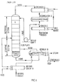
- With particular reference to Figure 1, a typical, prior art, continuous distillation or fractionating column equipped with the necessary auxiliary equipment and containing rectifying and stripping sections is shown. The column A is fed near its center with a feed of definite concentration. The feed is assumed to be a liquid at or near its boiling point. The plate on which the feed enters is called the feed plate. All plates above the feed plate constitute the rectifying section, and all plates below the feed, including the feed plate itself, constitute the stripping section. The liquid in the feed flows down the stripping section to the bottom of the column where a definite liquid level is maintained.
- Liquid is removed from the stripping section and flows by gravity to reboiler B that generates vapor and returns the vapor to the bottom of the stripping section portion of the column. The reboiler may be of the kettle (as shown), thermosyphon, forced circulation, etc., type. The bottom product may undergo-further processing or may flow (as shown) through a cooler H which also preheats the feed by heat exchange therewith.
- Vapor from reboiler B passes up the entire column through both the stripping and rectifying sections and is removed from the column and partially or totally condensed in a condenser C. The condensate is collected in an accumulator D from which reflux pump F removes liquid and delivers it to the top plate of the rectifying section. This liquid stream is called reflux and provides the down-flowing liquid in the rectifying section necessary to act on the upflowing vapor. Reflux liquid provides the required rectification since no rectification would occur in the rectifying section without the reflux. Without rectification the concentration of the overhead product would be no greater than in the vapor rising from the feed plate. Condensate from accumulator D that is not picked up by the reflux pump F is withdrawn as overhead product and may be cooled in a heat exchanger E, called the product cooler. If no azeotropes are encountered, both overhead and bottom products may be obtained in any desired purity if enough plates and adequate reflux are provided.
- It should be emphasized again that thermal energy is removed from the vapor in condenser C at a lower temperature than the thermal energy introduced into reboiler B. Accordingly, in the absence of any external device, it is not possible to transfer the low temperature thermal energy removed from condenser C into the higher temperature environment of reboiler B.
- The distillation system shown in figure 1 is usually simplified, especially in general chemical laboratories. For example, in place of the reboiler, a heating coil is placed in the bottom of the column and is used to generate vapor from the pool of liquid there. The condenser may also be placed above the top of the column with the reflux pump and accumulator omitted. Reflux then returns to the top plate by gravity while a special valve, called a reflux splitter, is used to control the rate of reflux return while the remainder of the condensate forms the overhead product.
- Various methods for increasing the thermodynamic efficiency of the distillation process are known and are discussed in numerous publications and include, for example, vapor recompression, vapor reuse, secondary reflux, and split tower configurations. Additional information regarding conventional distillation apparatus may be found in Unit Operations of Chemical Engineering, McCabe, W. L., and Smith, J. C., McGraw-Hill Book Company, Inc., New York, 1956.
- Additional information on fractional dis- 'tillation, including more efficient apparatus, can be found in a publication Elements of Fractional Distillation, Robinson, C. S. and Gilliland, E. R., fourth edition, McGraw-Hill Book Company Inc., New York (1950).
- Historically, energy supplies from fossil fuels (notably natural gas and petroleum) have been both cheap and plentiful, and it has, therefore, been difficult to justify the additional capital equipment and fabrication costs necessary to enhance the thermodynamic efficiency of the distillation column. However, recent increases in the cost of energy (particularly that derived from natural gas and petroleum) has placed an increased emphasis on enhancing distillation column thermodynamic efficiency or providing alternative low energy separation techniques that formerly could be dismissed summarily on economic grounds.
- A new distillation scheme using secondary reflux and vaporization to enhance thermodynamic efficiency is discussed in a paper "Distillation with Secondary Reflux and Vaporization: A Comparative Evaluation" by Mah, R. S. H., Nicholas, Jr., J. J., and Wodnik, R.B., AIChE Journal, Volume 23, Number 5, September, 1977 (pages 651-658).
- An object of the invention is to provide a continuous distillation apparatus in which thermal energy can be conserved vis-a-vis the prior art apparatus.
- This object is achieved according to the invention by providing a longitudinal divider completely separating the stripping section from the rectifying section and allowing the rectifying section to be operated at a higher temperature and pressure than the stripping section, and a plurality of pipes extending through the divider from the rectifying section to the stripping section for transferring thermal energy from the rectifying section to the stripping section. The rectifying section is operated at a higher temperature than the stripping section by compressing vapor from the stripping section prior to introducing the vapor into the rectifying section.
- In a preferred embodiment of the invention the contact stages are so arranged that liquid falling through each section flows alternately towards and away from the divider.
- In an alternative embodiment of the invention the contact stages are so arranged that liquid falling through each section flows substantially parallel to the divider.
- Ways of carrying out the invention are described in detail with reference to the accompanying drawings, which illustrate two embodiments and in which:
- Figure 1 is a schematic flow diagram of a prior art, continuous distillation column with rectifying and stripping sections in the same vessel.
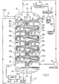
- Figure 2 is a schematic, vertical cross section of a first preferred embodiment of the continuous distillation apparatus of this invention illustrating the orientation of the rectifying section, stripping section and heat pipes, and
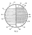
- Figure 3 is a schematic cross section of the tray and heat pipe layout of a second preferred embodiment of this invention.
- In Figures 2 and 3 like parts are designated with like numerals throughout.
- Referring now more particularly to Figure 2, the distillation or fractionating apparatus of a fist preferred embodiment of this invention is shown generally at 10 and includes a vertically oriented
column 12 configurated as a closed vessel and separated by adivider 18 into astripping section 14 and a rectifyingsection 16.Stripping section 14 is segregated into a plurality of vapor/liquid contacting stages 24-32 bytrays 20a-20i, respectively. Correspondingly, rectifyingsection 16 is segregated into a plurality of vapor/liquid contact stages 34-42 bytrays 22a-22i, respectively. - Each of vapor/liquid contacting stages 24-32 and 34-42 are conventional vapor/liquid contact stages and will be briefly described herein with the understanding that further description is unnecessary since the stages are conventional. Feed in the form of a multicomponent liquid stream is introduced into
stripping section 14 through aninlet 44 and forms ahydrostatic column 47, for example, behind aninlet weir 46. The liquid flows underweir 46 and acrosstray 20a thereafter over anoverflow weir 48. Vapor from vapor/liquid contactingstage 25 rises upwardly through perforations (not shown) intray 20a causing an intimate mixing and otherwise frothing of liquid ontray 20a. The overflowing liquid/froth from 'tray 20a collects in adowncomer 50 where it segregates into anupper froth section 51 and aliquid column 52 prior to the liquid flowing acrosstray 20b. The foregoing sequence is repeated for each of the remaining vapor/liquid contacting stages 25-32 until the liquid residue collects as areservoir 54 of liquid in the bottom portion ofstripping section 14. The liquid is drawn fromreservoir 54 and either directed as feed to reboiler 56 or is drawn off as bottom product throughoutlet 58. Clearly, other arrangements to separate bottom product from reboiler feed can also be employed. -
Reboiler 56 is configurated as a conventional reboiler having aninlet line 60 for any suitable heating medium such as steam, etc., and anexit line 61. The heating medium provides thermal energy to vaporize liquid as boilup vapor inreboiler 56 prior to introducing the boilup vapor through recycle line 62. Thereafter, the boilup vapor rises upwardly through each of vapor/liquid contacting stages 32-24 as in the manner previously set forth hereinbefore and combines with feed vapor to provide contacting vapor to rectifyingsection 16. - Vapor leaving the top of
stripping section 14 is directed bypipe 64 tocompressor 66.Compressor 66 suitably compresses the vapor prior to its being introduced into the bottom portion of rectifyingsection 16. Importantly,compressor 66 imparts sufficient pressure to vapor introduced into rectifyingsection 16 so that rectifyingsection 16 operates at a higher temperature thanstripping section 14. Compressed vapor introduced bycompressor 66 rises upwardly through each of vapor/liquid contacting stages 42-34 in a manner similar to the operation ofstripping section 14. - Overhead vapor is removed from rectifying
section 16 where it is condensed incondenser 68 by a suitable coolant passing betweeninlet 70 andoutlet 71. The condensed vapor is accumulated in anaccumulator 72 with a portion being returned as a liquid by areflux pump 74 through areflux return line 76. The remainder of the condensed vapor inaccumulator 72 is removed through anoutlet 78 as an overhead product. Alternatively, a vapor distillate can be removed fromaccumulator 72. - The reflux liquid returned through
inlet 76 is introduced into the vapor/liquid contact stage 34, for example, behind aweir 80 where it flows acrosstray 22a and over aweir 82. The countercurrent-like flow of liquid and vapor through stages 34-42 is substantially identical as in stage 24-32 of strippingsection 14. - A plurality of heat pipes, shown herein schematically as heat pipes 84-87,
transect divider 18 for the purpose of transmitting thermal energy from the various vapor/liquid contacting stages in rectifyingsection 16 into strippingsection 14. Heat pipes 84-87 are configurated as a plurality of conventional heat pipe apparatus which are sealed, two phase heat transfer devices and incorporate some form of capillary or osmotic forces to return heat pipe condensate to the heat pipe evaporator. - Heat pipe 84 is a representative heat pipe and may be configurated with a plurality of
fins 84a to provide an enlarged heat transfer surface at the heat pipe evaporator end.Fins 84a residue in rectifyingsection 16 where they extend into the vapor portion of liquid/vapor contacting stage 36. In this manner, upwardly rising vapor in liquid/vapor contacting stage 36 condenses onfins 84a absorbing the thermal energy released from the vapor into heat pipe 84. The thermal energy absorbed by heat pipe 84 is thereby transferred according to conventional heat pipe technology from rectifyingsection 16 to strippingsection 14. The opposite or upper end of heat pipe 84 is immersed in the liquid/froth portion of liquid/vapor contacting stage 25 so that the thermal energy is removed therefrom by the liquid/froth mixture. While only a single heat pipe 84 is illustrated, it is particularly understood that heat pipe 84 could be selectively configurated as a plurality of heat pipes in any suitable array and transectingdivider 18. - Furthermore, while heat pipes 84-87 are shown bridging between vapor/
liquid contacting stages vapor contacting stages trays 20a-20i are shown as substantiallycoplanar trays 22a-22i, respectively, the relative positions of the respective trays in each of strippingsection 14 and rectifyingsection 16 may be selectively offset, if desired, to provide the appropriate orientation of heat pipes 84-87. - Generally, the operation of heat pipes 84-87 requires that the heat evolution end be higher than the heat absorption end by nature of the functional characteristics of the conventional heat pipe. In particular, a working fluid is contained within the enclosed heat pipe and, upon absorption of thermal energy, is vaporized and travels upwardly to the heat evolution end. At the heat evolution end, the vaporized working fluid condenses giving up its heat of condensation and then migrates under gravity, along a wick, back to the lower, heat absorption end. This latter information is conventional heat pipe technology. However, heat pipe technology has advanced sufficiently whereby any suitable heat pipe orientation may be employed using the appropriate heat pipes.
- From the foregoing, it should be clear that the apparatus and method of this invention provides significant energy savings since rectifying
section 16 is operated at a higher temperature than strippingsection 14 thereby accommodating transfer of thermal energy from rectifyingsection 16 into strippingsection 14. Since rectifyingsection 16 is operated at a higher pressure than strippingsection 14, aconstriction valve 67 is incorporated into the outlet for liquid from rectifyingsection 16 prior to returning the same to strippingsection 14. Alternatively, a power-recovery turbine (not shown) can be substituted forvalve 67 thereby further enhancing thermodynamic efficiency. - While the primary heat transfer mechanism is provided by heat pipes 84-87, additional thermal energy is transferred from rectifying
section 16 to strippingsection 14 throughdivider 18. However, reliance on heat transfer throughdivider 18 alone is believed to be inadequate, and therefore, heat pipes 84-87 are included in the apparatus and method of this invention. From the foregoing, it should be clear that the continuous distillation apparatus and method of this invention utilizes and recovers thermal energy in a more efficient manner by creating secondary reflux and vaporization through internal heat exchange at spaced locations incolumn 12 as well as at the ends ofcolumn 12. - By way of illustration of the apparatus and method, the following nonlimiting example, taken from the previously cited reference of Mah, et al., is set forth:
- An equimolal feed mixture of ethylene and ethane at a flow rate of 0.126 kgmole/sec is separated into 99 mole percent pure products with 30 stages. The rectifying section operates at 911.0 kPa and the stripping section at 304.0 kPa. By transferring heat between various stages of this invention, the following reductions are made over ccnventional distillation:

compressor 66 and moving boilup vapor from strippingsection 14 to rectifyingsection 16. - A further comparison is made in the following Table I between the conventional distillation column with the apparatus of this invention:

- The foregoing comparison is set forth herein for the purpose of emphasizing the increase in thermodynamic efficiency of a distillation system using secondary reflux. Clearly, therefore, the present invention is significant in that it discloses a novel apparatus and method for transferring thermal energy from the rectifying section to the stripping section with heat pipe apparatus.
- Referring now more particularly to Figure 3, a second preferred embodiment of the distillation apparatus of this invention is illustrated schematically in cross section herein at 100 as a
closed vessel 102 segregated by adivider 108 into a strippingsection 104 and arectifying section 106. A plurality of heat pipes shown generally at 110transect divider 108 for the purpose of transferring thermal energy from rectifyingsection 106 to strippingsection 104. Operationally, each of strippingsection 104 andrectifying section 106 operate similarly to strippingsection 14 and rectifyingsection 16, respectively, (Figure 2). - The primary difference between the apparatus illustrated in Figure 3 and that illustrated in Figure 2 is that the configuration shown in Figure 3 is modified with respect to the flow path of the liquid traversing each of the stripping
section 104 andrectifying section 106. In both instances, the liquid (not shown) flows parallel todivider 108. The flow path for liquid through strippingsection 104 is between aninlet 112 from an overhead downcomer (not shown) acrosstray 114 and over anoutlet weir 116 into adowncomer 118 to the next succeeding tray therebelow. Correspondingly, countercurrent flow of liquid through rectifyingsection 106 is achieved by incoming fluid from aninlet 122 flowing acrosstray 124 over anoutlet weir 126 intodowncomer 128. Clearly, of course, any suitable flow arrangement can be made for the suitable contact between the liquid and vapor phases in each oftrays - Importantly,
heat pipes 110 transfer thermal energy from rectifyingsection 106 into strippingsection 104. To further improve thermodynamic efficiency, a plurality of fins, shown herein schematically asfins 120 onheat pipe 110, can be used to assist in conducting thermal energy intoheat pipes 110 wherein the thermal energy is then transferred into strippingsection 104. As set forth hereinbefore, the orientation ofheat pipes 110 with respect to each of strippingsection 104 and rectifying 106 may be any suitable orientation for the appropriate transfer of thermal energy. - From the foregoing, it is clear tha thermodynamic efficiencies achieved with secondary reflux and vaporization are substantially enhanced by the simplified construction and design provided by the incorporation of heat pipes therein. Importantly, the heat pipes transfer thermal energy from the rectifying section into the stripping section, the rectifying section being operated at a higher pressure to accommodate the necessary temperature differential between the two sections.
- Clearly, the apparatus set forth in each of Figures 2 and 3 is illustrative only and describes only the simpler distillation apparatus. However, the inventive concept is equally applicable to distillation processes involving multiple feed streams, multiple product streams, multiple side streams and multiple columns.
- The described embodiments are to be considered in all respects only as illustrative and not restrictive and the scope of the invention is, therefore, indicated by the appended claims rather than by the foregoing description.
Claims (9)
Applications Claiming Priority (2)
| Application Number | Priority Date | Filing Date | Title |
|---|---|---|---|
| US05/950,969 US4234391A (en) | 1978-10-13 | 1978-10-13 | Continuous distillation apparatus and method |
| US950969 | 2001-09-12 |
Publications (2)
| Publication Number | Publication Date |
|---|---|
| EP0010253A1 EP0010253A1 (en) | 1980-04-30 |
| EP0010253B1 true EP0010253B1 (en) | 1981-11-04 |
Family
ID=25491104
Family Applications (1)
| Application Number | Title | Priority Date | Filing Date |
|---|---|---|---|
| EP79103872A Expired EP0010253B1 (en) | 1978-10-13 | 1979-10-09 | Continuous distillation apparatus and method of operation |
Country Status (5)
| Country | Link |
|---|---|
| US (1) | US4234391A (en) |
| EP (1) | EP0010253B1 (en) |
| JP (1) | JPS5554002A (en) |
| CA (1) | CA1137440A (en) |
| DE (1) | DE2961269D1 (en) |
Families Citing this family (50)
| Publication number | Priority date | Publication date | Assignee | Title |
|---|---|---|---|---|
| US4328074A (en) * | 1980-11-12 | 1982-05-04 | Resources Conservation Company | Production of concentrated alcohol and distillery slop |
| US4582569A (en) * | 1981-01-22 | 1986-04-15 | Distillation Technology Limited | Mass transfer apparatus |
| US5124004A (en) * | 1983-08-22 | 1992-06-23 | Trustees Of Dartmouth College | Distillation process for ethanol |
| US4615770A (en) * | 1983-10-14 | 1986-10-07 | Rakesh Govind | Distillation column and process |
| US4681661A (en) * | 1983-10-14 | 1987-07-21 | Rakesh Govind | Dual distillation columns |
| US4617093A (en) * | 1984-02-08 | 1986-10-14 | University Of Cincinnati | Method and apparatus for separating components of a mixture |
| US4657638A (en) * | 1985-07-29 | 1987-04-14 | University Of Florida | Distillation column |
| US4961826A (en) * | 1986-02-13 | 1990-10-09 | Trustees Of Dartmouth College | Distillation process for ethanol |
| US5289688A (en) * | 1991-11-15 | 1994-03-01 | Air Products And Chemicals, Inc. | Inter-column heat integration for multi-column distillation system |
| US5230217A (en) * | 1992-05-19 | 1993-07-27 | Air Products And Chemicals, Inc. | Inter-column heat integration for multi-column distillation system |
| DE69529146T2 (en) * | 1994-08-29 | 2003-11-13 | Kansai Chemical Engineering Co., Ltd. | DISTILLATION COLUMN WITH INTERNAL HEAT EXCHANGE |
| US5592832A (en) * | 1995-10-03 | 1997-01-14 | Air Products And Chemicals, Inc. | Process and apparatus for the production of moderate purity oxygen |
| US5837107A (en) * | 1995-12-20 | 1998-11-17 | Basf Aktiengesellschaft | Process for production of aqueous solutions of free hydroxylamine |
| US6605190B1 (en) | 1997-02-14 | 2003-08-12 | San Diego State University Foundation | Staged optimal externally-controlled systems and method thereof |
| US5802858A (en) * | 1997-03-27 | 1998-09-08 | Praxair Technology, Inc. | Cryogenic cooling tower |
| AUPO775697A0 (en) * | 1997-07-07 | 1997-07-31 | Inland Oil Refiners (Qld) Pty Ltd | Method and apparatus for fractional distillation |
| US6365006B1 (en) * | 1997-10-01 | 2002-04-02 | General Electric Company | Method for distilling a mixture of substances and device for realizing the same |
| US6212906B1 (en) | 2000-02-16 | 2001-04-10 | Praxair Technology, Inc. | Cryogenic reflux condenser system for producing oxygen-enriched air |
| FI111187B (en) * | 2001-10-10 | 2003-06-13 | Matti Nurmia | Under normal pressure working process for producing oxygen or oxygen enriched air |
| EP1332781A1 (en) * | 2002-01-25 | 2003-08-06 | Technische Universiteit Delft | Heat integrated distillation column |
| JP4496958B2 (en) | 2002-06-28 | 2010-07-07 | 関西化学機械製作株式会社 | Internal heat exchange distillation column |
| US7678235B2 (en) * | 2005-10-19 | 2010-03-16 | Sylvan Source, Inc. | Water purification system |
| US20070068791A1 (en) * | 2003-12-02 | 2007-03-29 | Thom Douglas M | Automated water processing control system |
| EP1769200A2 (en) * | 2004-06-30 | 2007-04-04 | Transborder Marketing, LLC | Reversible absorption refrigeration |
| US7357378B2 (en) * | 2004-10-18 | 2008-04-15 | Air Prodcuts And Chemicals, Inc. | Divided wall exchange column |
| WO2007047674A2 (en) * | 2005-10-14 | 2007-04-26 | Sylvan Source, Inc. | Energy-efficient distillation system |
| US7815876B2 (en) | 2006-11-03 | 2010-10-19 | Olson David A | Reactor pump for catalyzed hydrolytic splitting of cellulose |
| US7815741B2 (en) | 2006-11-03 | 2010-10-19 | Olson David A | Reactor pump for catalyzed hydrolytic splitting of cellulose |
| DE102007004788A1 (en) | 2007-01-31 | 2008-08-07 | Bayer Technology Services Gmbh | Process for the distillation of a biologically produced alcohol |
| US8002952B2 (en) * | 2007-11-02 | 2011-08-23 | Uop Llc | Heat pump distillation |
| US7981256B2 (en) * | 2007-11-09 | 2011-07-19 | Uop Llc | Splitter with multi-stage heat pump compressor and inter-reboiler |
| US20090166170A1 (en) * | 2007-12-26 | 2009-07-02 | Gary Sun | Porous honeycomb water treatment device |
| US20090314624A1 (en) * | 2008-06-24 | 2009-12-24 | Albers Walter F | Energy efficient distillation system and method |
| US20100101273A1 (en) * | 2008-10-27 | 2010-04-29 | Sechrist Paul A | Heat Pump for High Purity Bottom Product |
| US8182654B2 (en) | 2008-10-27 | 2012-05-22 | Uop Llc | Heat pump for high purity bottom product |
| JP4803470B2 (en) * | 2009-10-05 | 2011-10-26 | 独立行政法人産業技術総合研究所 | Heat exchange type distillation equipment |
| US20110144404A1 (en) * | 2009-12-14 | 2011-06-16 | Uop Llc | MTO Feed Purification |
| US20120085126A1 (en) | 2010-10-06 | 2012-04-12 | Exxonmobil Research And Engineering Company | Low energy distillation system and method |
| CN102453493B (en) * | 2010-10-26 | 2014-04-30 | 中国石油化工股份有限公司 | Fractionating column feeding method for improving yield of distillate oil |
| FR2982274B1 (en) * | 2011-11-09 | 2014-03-14 | Commissariat Energie Atomique | BIOMASS TORREFACTION AND GRINDING REACTOR, BIOMASS TREATMENT SYSTEM AND PLANT INCORPORATING SUCH REACTOR, PROCESS THEREOF |
| JP5956772B2 (en) * | 2012-02-20 | 2016-07-27 | 東洋エンジニアリング株式会社 | Heat exchange type distillation equipment |
| JP5923335B2 (en) * | 2012-02-24 | 2016-05-24 | 東洋エンジニアリング株式会社 | Heat exchange type distillation equipment |
| JP5923367B2 (en) * | 2012-03-30 | 2016-05-24 | 東洋エンジニアリング株式会社 | Heat exchange type distillation equipment |
| JP6006596B2 (en) * | 2012-09-21 | 2016-10-12 | 東洋エンジニアリング株式会社 | Stripper for separation process of aromatic production apparatus and operation method thereof |
| US20140262729A1 (en) * | 2013-03-14 | 2014-09-18 | Elwha Llc | Heat transfer between a distillation column and a temperature source |
| CN104001343B (en) * | 2014-05-14 | 2015-10-28 | 华南理工大学 | A kind of internally heat integrated rectifying column of augmentation of heat transfer |
| JP6658259B2 (en) * | 2016-04-22 | 2020-03-04 | 株式会社Ihi | Separation device |
| US10792586B2 (en) * | 2018-03-29 | 2020-10-06 | Uop Llc | Folded fractionation column and process |
| US10792585B2 (en) * | 2018-03-29 | 2020-10-06 | Uop Llc | Folded fractionation column and process |
| FR3116210B1 (en) * | 2020-11-17 | 2023-10-20 | Air Liquide | Low temperature distillation apparatus |
Family Cites Families (22)
| Publication number | Priority date | Publication date | Assignee | Title |
|---|---|---|---|---|
| DE299804C (en) * | 1913-11-02 | 1917-08-01 | ||
| US1690108A (en) * | 1924-10-30 | 1928-11-06 | Charles B Grady | Heat exchanger |
| US1915681A (en) * | 1930-03-29 | 1933-06-27 | Standard Oil Dev Co | Apparatus for fractionating cracked products |
| US2040431A (en) * | 1930-04-23 | 1936-05-12 | Foster Wheeler Corp | Fractionating apparatus |
| US2152164A (en) * | 1935-05-13 | 1939-03-28 | Theodore O Wentworth | Distillation process |
| US2134882A (en) * | 1935-07-26 | 1938-11-01 | Standard Oil Co | Fractionating apparatus and method of fractionation |
| US2760351A (en) * | 1952-12-12 | 1956-08-28 | Air Prod Inc | Fractionating apparatus |
| US3213000A (en) * | 1958-12-05 | 1965-10-19 | Aqua Chem Inc | Multiple stage flash evaporator |
| NL129275C (en) * | 1959-02-27 | |||
| NL259943A (en) * | 1959-11-06 | 1900-01-01 | ||
| US3288686A (en) * | 1963-07-12 | 1966-11-29 | Donald F Othmer | Method for multi-flash evaporation to obtain fresh water from aqueous solution |
| US3350298A (en) * | 1963-10-29 | 1967-10-31 | Callery Chemical Co | Process for the recovery of water from saline solutions |
| DE1517468C3 (en) * | 1964-12-12 | 1974-01-03 | Maschinenfabrik Augsburg-Nuernberg Ag, 8000 Muenchen | Process for obtaining fresh water from sea water |
| US3304242A (en) * | 1965-11-19 | 1967-02-14 | Lockman Carl Johan | Multi-stage flash evaporators |
| US3414484A (en) * | 1966-06-20 | 1968-12-03 | Universal Oil Prod Co | Process for separating ethylbenzene from c8 aromatic hydrocarbons by super-distillation with vapor compression-reboiler heat exchange |
| US3563047A (en) * | 1967-08-04 | 1971-02-16 | Mc Donnell Douglas Corp | Production of high purity oxygen from air |
| NL6817235A (en) * | 1967-12-06 | 1969-06-10 | ||
| US3575007A (en) * | 1968-03-26 | 1971-04-13 | Treadwell Corp | Isothermal fractional distillation of materials of differing volatilities |
| IT972794B (en) * | 1972-12-22 | 1974-05-31 | Sir Soc Italiana Resine Spa | PERFECTED PROCESS FOR THE PRODUCTION OF ETHYLENE GLYCOL |
| GB1508603A (en) * | 1974-04-11 | 1978-04-26 | Haselden G | Distillation processes and apparatus |
| US4033406A (en) * | 1974-09-03 | 1977-07-05 | Hughes Aircraft Company | Heat exchanger utilizing heat pipes |
| US4037786A (en) * | 1975-08-15 | 1977-07-26 | International Telephone And Telegraph Corporation | Energy recovery and storage system |
-
1978
- 1978-10-13 US US05/950,969 patent/US4234391A/en not_active Expired - Lifetime
-
1979
- 1979-10-09 DE DE7979103872T patent/DE2961269D1/en not_active Expired
- 1979-10-09 EP EP79103872A patent/EP0010253B1/en not_active Expired
- 1979-10-09 JP JP13071979A patent/JPS5554002A/en active Pending
- 1979-10-12 CA CA000337499A patent/CA1137440A/en not_active Expired
Also Published As
| Publication number | Publication date |
|---|---|
| DE2961269D1 (en) | 1982-01-14 |
| EP0010253A1 (en) | 1980-04-30 |
| US4234391A (en) | 1980-11-18 |
| CA1137440A (en) | 1982-12-14 |
| JPS5554002A (en) | 1980-04-21 |
Similar Documents
| Publication | Publication Date | Title |
|---|---|---|
| EP0010253B1 (en) | Continuous distillation apparatus and method of operation | |
| US8273220B2 (en) | Heat pump distillation | |
| US6601406B1 (en) | Methods and apparatus for high propane recovery | |
| US5257505A (en) | High efficiency nitrogen rejection unit | |
| US4455158A (en) | Nitrogen rejection process incorporating a serpentine heat exchanger | |
| US3822192A (en) | Evaporative method | |
| KR20110074743A (en) | Improved heat pump for high purity bottoms products | |
| US2690060A (en) | Fractional distillation | |
| CA1125218A (en) | Process and apparatus for reducing the energy required to separate liquids by distillation | |
| Long et al. | Advances in distillation retrofit | |
| KR0141439B1 (en) | Process for preparing krypton / xenon concentrate streams directly from main air distillation column | |
| JPS61167402A (en) | Rectification method | |
| KR930000280B1 (en) | Process and apparatus for preparing ultra high purity oxigen from a gaseous feed | |
| WO1997001068A1 (en) | Method and apparatus for separating argon | |
| US4460396A (en) | Method for producing purified ethylene through thermo-coupled distillation and ethylene-producing apparatus using the said method | |
| US4484983A (en) | Distillation and vapor treatment process | |
| KR100502254B1 (en) | Structured packing system for reduced distillation column height | |
| US3238735A (en) | Distillation of low-boiling components | |
| GB2325175A (en) | Heat exchanger | |
| US2502251A (en) | Apparatus for the separation of gaseous mixtures | |
| US6024842A (en) | Distillation column device | |
| US4484986A (en) | Process for distillation and condensation | |
| US5252201A (en) | Fractionating process and fractionator | |
| US4484985A (en) | Distillation and condensing process | |
| US20210055047A1 (en) | Method and appliance for separating a synthesis gas by cryogenic distillation |
Legal Events
| Date | Code | Title | Description |
|---|---|---|---|
| PUAI | Public reference made under article 153(3) epc to a published international application that has entered the european phase |
Free format text: ORIGINAL CODE: 0009012 |
|
| AK | Designated contracting states |
Designated state(s): DE FR GB IT |
|
| 17P | Request for examination filed | ||
| ITF | It: translation for a ep patent filed | ||
| GRAA | (expected) grant |
Free format text: ORIGINAL CODE: 0009210 |
|
| AK | Designated contracting states |
Designated state(s): DE FR GB IT |
|
| REF | Corresponds to: |
Ref document number: 2961269 Country of ref document: DE Date of ref document: 19820114 |
|
| PGFP | Annual fee paid to national office [announced via postgrant information from national office to epo] |
Ref country code: FR Payment date: 19841009 Year of fee payment: 6 |
|
| PGFP | Annual fee paid to national office [announced via postgrant information from national office to epo] |
Ref country code: DE Payment date: 19841106 Year of fee payment: 6 |
|
| PG25 | Lapsed in a contracting state [announced via postgrant information from national office to epo] |
Ref country code: FR Free format text: LAPSE BECAUSE OF NON-PAYMENT OF DUE FEES Effective date: 19870630 |
|
| PG25 | Lapsed in a contracting state [announced via postgrant information from national office to epo] |
Ref country code: DE Effective date: 19870701 |
|
| REG | Reference to a national code |
Ref country code: FR Ref legal event code: ST |
|
| GBPC | Gb: european patent ceased through non-payment of renewal fee | ||
| PG25 | Lapsed in a contracting state [announced via postgrant information from national office to epo] |
Ref country code: GB Effective date: 19881118 |
|
| PLBE | No opposition filed within time limit |
Free format text: ORIGINAL CODE: 0009261 |
|
| STAA | Information on the status of an ep patent application or granted ep patent |
Free format text: STATUS: NO OPPOSITION FILED WITHIN TIME LIMIT |