EP0008455A1 - Method of and apparatus for providing information as to the existence or position of objects - Google Patents
Method of and apparatus for providing information as to the existence or position of objects Download PDFInfo
- Publication number
- EP0008455A1 EP0008455A1 EP79103049A EP79103049A EP0008455A1 EP 0008455 A1 EP0008455 A1 EP 0008455A1 EP 79103049 A EP79103049 A EP 79103049A EP 79103049 A EP79103049 A EP 79103049A EP 0008455 A1 EP0008455 A1 EP 0008455A1
- Authority
- EP
- European Patent Office
- Prior art keywords
- indicator
- field
- signal
- frequency
- providing
- Prior art date
- Legal status (The legal status is an assumption and is not a legal conclusion. Google has not performed a legal analysis and makes no representation as to the accuracy of the status listed.)
- Granted
Links
Images


Classifications
-
- G—PHYSICS
- G09—EDUCATION; CRYPTOGRAPHY; DISPLAY; ADVERTISING; SEALS
- G09B—EDUCATIONAL OR DEMONSTRATION APPLIANCES; APPLIANCES FOR TEACHING, OR COMMUNICATING WITH, THE BLIND, DEAF OR MUTE; MODELS; PLANETARIA; GLOBES; MAPS; DIAGRAMS
- G09B21/00—Teaching, or communicating with, the blind, deaf or mute
- G09B21/001—Teaching or communicating with blind persons
- G09B21/007—Teaching or communicating with blind persons using both tactile and audible presentation of the information
-
- G—PHYSICS
- G01—MEASURING; TESTING
- G01S—RADIO DIRECTION-FINDING; RADIO NAVIGATION; DETERMINING DISTANCE OR VELOCITY BY USE OF RADIO WAVES; LOCATING OR PRESENCE-DETECTING BY USE OF THE REFLECTION OR RERADIATION OF RADIO WAVES; ANALOGOUS ARRANGEMENTS USING OTHER WAVES
- G01S15/00—Systems using the reflection or reradiation of acoustic waves, e.g. sonar systems
- G01S15/02—Systems using the reflection or reradiation of acoustic waves, e.g. sonar systems using reflection of acoustic waves
- G01S15/06—Systems determining the position data of a target
- G01S15/08—Systems for measuring distance only
- G01S15/32—Systems for measuring distance only using transmission of continuous waves, whether amplitude-, frequency-, or phase-modulated, or unmodulated
- G01S15/34—Systems for measuring distance only using transmission of continuous waves, whether amplitude-, frequency-, or phase-modulated, or unmodulated using transmission of continuous, frequency-modulated waves while heterodyning the received signal, or a signal derived therefrom, with a locally-generated signal related to the contemporaneously transmitted signal
-
- Y—GENERAL TAGGING OF NEW TECHNOLOGICAL DEVELOPMENTS; GENERAL TAGGING OF CROSS-SECTIONAL TECHNOLOGIES SPANNING OVER SEVERAL SECTIONS OF THE IPC; TECHNICAL SUBJECTS COVERED BY FORMER USPC CROSS-REFERENCE ART COLLECTIONS [XRACs] AND DIGESTS
- Y10—TECHNICAL SUBJECTS COVERED BY FORMER USPC
- Y10S—TECHNICAL SUBJECTS COVERED BY FORMER USPC CROSS-REFERENCE ART COLLECTIONS [XRACs] AND DIGESTS
- Y10S367/00—Communications, electrical: acoustic wave systems and devices
- Y10S367/91—Portable sonar devices
Definitions
- This invention relates to a method of and apparatus for providing information as to the existence or position of objects otherwise than by direct vision.
- a method to which the invention relates comprises the steps a radiating stress wave energy (herein called the transmitted signal) from a station to a field of view, receiving at the station at least part of the transmitted signal (such part herein being called the received signal) reflected from the object, carrying out a frequency modulation to produce a frequency difference between the received signal and a locally generated signal in a mode such that the magnitude of the frequency difference represents the range of the object from the station, operating upon the received signal of said difference frequency providing for range indication, and determining or sensing the angular position of the object with respect to a reference axis extending through the station and the field of view by observation of a characteristic of the indicator signal which is dependent upon the angular position of the object.
- the transmitted signal radiating stress wave energy
- the apparatus to which the invention relates (hereinafter referred to as being of the kind specified) comprises a transmitting means for transmitting stress wave energy (herein called the transmitted signal) from a station to a field of view, receiving means at the station for receiving at least part of the wave energy (this part herein being called the received signal) reflected from an object in the field of view, frequency modulating means for producing a frequency difference between the received signal and a locally generating signal in a mode such that the magnitude of the frequency difference is representative of the range of the object from the station, means for providing the locally generated signal and for feeding same to said frequency modulating means to produce therefrom an indicator signal of said difference frequency, and indicator means responsive to said indicator signal to furnish observable range and direction information.
- the transmitted signal stress wave energy
- receiving means at the station for receiving at least part of the wave energy (this part herein being called the received signal) reflected from an object in the field of view
- frequency modulating means for producing a frequency difference between the received signal and a locally generating signal in a mode such
- the stress wave energy shall be radiated at a frequency above audibility i.e. supersonic.
- the polar lobe characteristics are designed to match the characteristics of the human auditory neural system so that a blind person wearing the head-set can sense the direction from which a reflection of the transmitted signal is received, and, of course, can also make a subjective determination of the range by virtue of the frequency of the indicator signal.
- the prior forms of apparatus referred make use of audible indicator means, indeed essentially so, where the characteristics of the human auditory neural system is to be simulated.
- audible indicator means indeed essentially so, where the characteristics of the human auditory neural system is to be simulated.
- other forms of indicator means may be advantageously employed, for example visual indicator means or tactile indicator means both providing sensually perceptible indications of range and direction.
- the purpose of the present invention is to provide an improved method and apparatus by means of which object character recognition is enhanced when utilizing an aural indicator means, and which solves certain problems (more conveniently explained hereafter) which are entailed when visual or tactile indicator means are employed.
- a method of providing information of the kind specified is characterised by the steps of radiating the stress wave energy into the field of view in the form of a beam, moving the beam angularly from a datum position occupied at a datum time to effect scanning of a field of view successively to irradiate objects contained in successive sectors of the field of view having angular widths corresponding to that of the beam, and displaying the indicator signal derived from the received signals due to these objects in a manner providing an indication of the sector of the field of view in which the beam is located while irradiating each object.
- the display of the indicator signal may include providing sensually perceptible stimuli spaced apart in one dimension in a manner corresponding to the scanning position of the beam, and spaced apart in another dimension in a manner corresponding to the range of the object.
- one form of display of this character may be visual employing stimulation of the face of a cathode ray-tube, and another form may be stimulation of a matrix of tactile elements such as vibratory pins arranged in rows corresponding to different ranges and columns corresponding to different sectors of the field.
- the method is preferably further characterized in that indicator signals due to objects said different ranges are subjected, before producing the stimuli, to different delays to bring them into coincident time relation at different respective outlets. These outlets are subjected to sequential scanning to generate the respectively spaced stimuli.
- the invention provides an apparatus of the kind specified characterized in that the transmitting means includes a transmitting transducer means providing a beam, and scanning means for moving the beam angularly from a datum position occupied at a datum time to effect scanning of the field of view, successively to irradiate objects contained in successive sectors of the field of view, such sectors having angular widths corresponding that of the beam, and in that the indicator means is responsive both to the frequency of the indicator signal and to the angular position of the beam to provide for sensory perception respectively of range of each object and the sector of the field of view in which the beam is located while irradiating each object.
- the indicator means may comprise coordinate display means providing sensually perceptible stimuli spaced apart in a first dimension in a manner corresponding to the scanning position of the beam, and spaced apart in a second dimension in a manner corresponding to the range of the object.
- the receiving means includes means for segregating indicator signals derived from received signals due respectively to objects at different ranges to different respective outlets of the receiving means one for each range band, means for subjecting the segregated indicator signal to delays differing in a manner such as to bring them into coincident time relation, and switch means for sampling said outlets successively to feed indicator signals therefrom to said coordinate display means along said second dimension.
- the indicator means provides, or includes, an audible display, character recognition arising from the different frequency components due to multiple reflections from object surfaces at different distances, and in some cases from movement of these surfaces, will be enhanced because of irradiation of the object by means of the narrow concentrated beam.
- the apparatus may include means for arresting scanning of the beam at any desired position, and this enables the user to concentrate on character recognition of an object situated in a particular sector of the field of view without any distraction of indicator signals received on objects in other sectors. If more than one object should be present in a given sector, such objects would be resolved by a different basic frequency of indicator signal, or, if the objects were close to each other and resulting tone produced by two basic frequencies differing only slightly from each other would be recognised by a skilled observer.
- the problem arises that the transit time of radiation outwardly through the field to an object and back again may be comparable with, or at least significant in relation to, the time taken for scanning of the transmitter beam from the datum position (corresponding to datum time) and the position of the beam in which it points towards the object.
- the stimulus representing a particular object could be displayed at a position along the first dimension (representing position of the beam) in advance of the proper position, because the beam would have moved on to this advanced position by the time the received signal arrived at the receiving means.
- the problem is solved by effectively subtracting the transit time from an equation representing the time to move the scanning beam from the datum position to the direction of the object thus, in accordance with this feature of the invention respectively differing delays are applied to the indicator signals segregated to respective outlets (and each representing a particular range at which objects are situated.
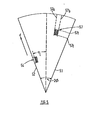
- a multi-transducer element 10 comprising a strip array of transducer elements 10a, 10j is provided to radiate stress wave energy at supersonic frequency having a typical mid frequency value of 60KHz into the environment of interest in the form of a narrow beam the effect of which is depicted in Figure 1.
- the latter shows a field of view having an origin 11 and radial-angular boundaries 12 and 13, and which is shown sub-divided into equal angular sectors corresponding to the angular width of the beam and denoted by dashed lines such as 7.
- the field of view, and motion of the beam hereinafter described is in azimuth and that the beam is of a wider angular form in elevation, for example having an angular width of 20 to 40 degrees, but in practice the scan of the beam could be in any plane between horizontal and vertical, and the angular width of the beam in a plane at right angles to that in which scanning takes place could be greater or less than mentioned.
- the apparatus includes means for causing the beam to scan angularly between boundary 12 and boundary 13 either step-wise, or continuously, and such scanning means comprises a voltage controlled oscillator 14 which generates a cyclic wave form, the shape, amplitude, and repetition rate being determined by the setting of an adjustable scanning rate control circuit 16.
- Shape determines the mode of scan, e.g. stepped or continuous, and direction of scan, amplitude determines the angular extent of scan of the beam with instantaneous magnitude determining the angular position of the beam at any such instant, and repetition rate determines the repetition rate of scan of the beam.
- the output of the oscillator 14 controls a further voltage control oscillator 17 which produces a series of square wave clock pulses indicated at 18 having a period proportion to ⁇ , and these pulses 18 are fed to an analogue delay line 19 which provides a series of incremental delays in an input signal fed into the delay line on conductor 20. Each increment is of a magnitude dependent upon the subsisting value of the repetition rate of the clock pulse 18.
- the transducer elements 10a to 10j are connected respectively to elements of the delay line 19 so that at one end of the transducer array the signal reaching the element 10i is subjected to only one increment of delay whereas the signal reaching the transducer element 10a is subjected to the aggregate of all the incremental delays along the line.
- the output wave form from circuit 14 will be stepped so that the repetition rate of circuit 17 will rise (or fall) in steps.
- the output wave form from circuit 14 will be a saw-tooth as shown at 15 so that the repetition rate of circuit 17 rises continuously, e.g. linearly and then reverts to the value subsisting when the beam is in its datum position.
- control means designated generally by the arrow 16a are provided. Such control means may be operable to adjust the output voltage level to circuit 17 to enable the user to "bracket" the beam to centre it on an object before setting the voltage to a constant level to hold the beam in a fixed.position. If desired a switch such as a pushbutton switch could be provided for manual operation to hold the value of output voltage instantaneously and stop beam scanning without prior "bracketing".
- connection between the elements of the delay line and respective transducer elements are made through the intermediary of electronic switch units 21a to 21j, and through power amplifiers 22a to 22j (only certain of which units and amplifiers are shown for the sake of simplicity).
- the switch units 21a to 21j each have two output terminals, shown typically in the case of unit 21a as a, b, and these are connected respectively to transducer element 10a, 10j.
- the two corresponding output terminals are connected to respective transducer elements occupying corresponding positions at equal distances from the centre of a transducer array outwardly towards its ends.
- the signals to be radiated are supplied through conductor 20 at a supersonic frequency, such as that already mentioned, and are derived from a transmitter signal generator or oscillator 23 which generates a frequency modulated output sweeping linearly from an upper frequency typically 80KHz to a lower frequency 40KHz in accordance with the falling saw-tooth wave form as shown in unit 23.
- a transmitter signal generator or oscillator 23 which generates a frequency modulated output sweeping linearly from an upper frequency typically 80KHz to a lower frequency 40KHz in accordance with the falling saw-tooth wave form as shown in unit 23.
- the choice of midfrequency, sweep range, and sweep rate is dependent upon parameters such as the medium (air or water), transmitting and receiving transducer capably as to bandwidth, and the maximum range required or attainable with the power output envisaged, but there should be at least one complete sweep of frequency for each sector of the field.
- the output of the signal generator 23 is fed through a frequency shaping network 24 to the conductor 20.
- This frequency shaping network is frequency responsive and would typically be designed to increase the amplitude of the higher frequency components of the frequency modulated output from unit 23 relatively to the lower frequency components,since it is the higher frequency component which are more effective in imparting distinctive tonal characteristics in the indicator signal ultimately derived.
- the transducer array 10 by reason of its length or the spacing of the transducer elements, intrinsically produces a narrow beam of radiation.
- the angular width of the beam may be 5 degrees (that is to say its polar diagram will intersect with radius vectors at a 5 degree separation at points providing a 6db reduction in power).
- the field of view may, as depicted in Figure 1, be approximately 60 degrees. These angles, however, are intended to be illustrative rather than limiting, but in general terms it is contemplated that the angular width of the beam would be in the range 3 to 10 degrees so that a plurality of beam width would be contained in a typical field of view.
- Stepped increases in the delay brought about by incidence stepped changes of the clock pulse repetition rate cause the median axis 26 of the beam be stepped left or right increasingly.
- the clock pulse rate which is subsisting when the beam is pointing just to the left of the reference axis 25 is arranged also to change over the electronic switches 21a, 21j, so that further clock pulses then continue the stepping of the beam in the same direction, and the scan can be stepwise starting from boundary 12 and finishing at boundary 13 as shown in Figure 1.
- a typical position of the wave front 27, representing maximum radiation is shown at an angle 9 is the reference axis 25.
- a time delay network namely the analogue delay line 19 is employed because a phase delay network cannot be operated over the wide frequency range of the radiated signal.
- Figure 1 depicts outwardly travelling "packets" 9 of wave energy in respective sectors showing that the field of view is energised in a manner analogously to supplying water through a hose-pipe moved stepwise.
- Packets" 8 of energy represent certain of those radiated in a preceding scan.
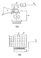
- this includes receiving transducer means which may comprise three separate transducers 28L 28R feeding left and righthand channels 1, 11 of the receiving means, these transducers being spaced apart one on each side of a central receiving transducer 28 feeding receiver channel 111.
- the receiver transducer means provides a polar diagram of sufficiently wide beam width to receive reflections from any object in the field of view, the transducers also having wide band width characteristics to ensure reception of received signals within the range of the transmitter frequency sweep.
- the received signals are amplified in the three channels by amplifiers 29L 29R and 29, are subjected to frequency shaping in circuits 30L, 30R and 30 and are then fed to modulator circuits which may be product modulators 31L 31R 31.
- modulator circuits which may be product modulators 31L 31R 31.
- a locally generated signal having a swept frequency characteristic conforming to that GF the transmitted signal is conveniently derived from the transmitter generator 23, and is fed as a separate input to the modulator circuits 31L 31R 31 on lone 32.
- the outputs from the modulator circuits 31L 31R 31, each of which includes filter means, comprises an indicator signal of difference frequency between the frequency of the received signal and the locally generated signal fed on line 32, and is therefore representative of the range of the object giving rise to the received signal, these indicator signals being fed in the channels to frequency responsive circuits 33L 33R 33.
- the frequency shaping circuits 30L 30R and 30 are provided for the purpose of accentuating the frequency components which give rise to distinctive tonal qualities in the indicator signals, and therefore are designed to increase the magnitude of a higher frequency components or reduce the magnitude of the lower frequency components. Such frequency shaping could also be effected by the use alternatively, or in addition, of transmitting and/or receiving transducers having such characteristics.
- the frequency responsive circuits 33L 33R and 33 are, on the other hand, to compensate for attenuation in the medium through which the signal is transmitted and reflected, namely air or water. Since the attenuation will be greater at longer ranges, corresponding to higher frequency indicator signals, again, these circuits are designed to increase the amplitude of the higher frequency component relatively to the lower frequency components or attenuate the latter.
- the receiving means may include indicator means providing an audible display, and as shown this comprises sound reproducers,head-phones or stereo loud speakers 34L 34R,providing binaural display and fed respectively through amplifiers 35L 35 R in channels I, II. Further, a monaural display may be provided by a single sound reproducer namely a head-phone or loudspeaker 34 connected to the output of amplifier 35 in channel III.
- the indicator means includes coordinate display means providing sensually perceptible stimuli spaced apart in a first dimension in a manner corresponding to the scanning position of the beam, and spaced apart in a second dimension in a manner corresponding to the range of the object.
- coordinate display means providing sensually perceptible stimuli spaced apart in a first dimension in a manner corresponding to the scanning position of the beam, and spaced apart in a second dimension in a manner corresponding to the range of the object.
- Alternative forms of such display means are illustrated in Figures 3 and 4 the former comprising essentually a cathode ray-tube on the face of which a plan position indicator type of display is established, and the latter comprising a tactile display device intended for use by blind persons, or others in situations where coordinate display is required but visual presentation is not possible, or is inconvenient.
- these displays may be regarded as duplicating or simulating analysing functions of the human cochlear and in particular that of discriminating between the different frequencies at which the indicator signals are developed.
- the receiving means may be provided with means for effecting spectral analysis into respective frequency bands.
- these means comprise a bank of filters 36 designated f1 to f7 and each designed to pass a band of frequencies (the band may be substantially equal in each case), which differ from each other but collectively cover the whole range of frequency at which the indicator signals are developed.
- this frequency range will be within audible limits, but in the absence of audible display means the frequency range could be wholly, or in part, outside the audible range.
- This filter bank is fed from amplifier 35 in channel III, and individual filters are connected through the intermediary of respective delay units d1 to d7 to respective input terminals of a sampling means in the form ' -of a switch 37.
- Filter f1 is assumed to pass the lowest pass band of frequencies corresponding to minimum range, and filter f7 the highest pass band of frequencies, representing the maximum range, the delays provided by the respective delay-units d1 to d7 being in ascending order of delay that is d1 providing the greatest delay and d7 the least. This is to compensate for transit time of the signal out from the the transmitting transducer means 10 and back to the receiver transducer means 28, as explained in more detail hereafter.
- the sampling switch 37 has a range output terminal 38 which has a stepped signal output having a number of levels corresponding to the number of filters f1 to f7, and a signal output terminal 39 which is connected successively by the sampling switch 37 to each of the delay units d1 to d7 so the terminal 39 receives successive signals (when such are present) at the outlets of filters f1 to f7.
- the output of terminal 38 may be continuously rising (or falling) at the same averge rate as the stepped output.
- the coordinate display means requires an input to develop direction indication, and this is derived from the saw-tooth generator 14 but requires to be delayed, and for this purpose in the output from the circuit 14 is supplied to direction terminal 40 through a delay circuit 41.
- this comprises a cathode ray-tube 42 a time base circuit 43 providing outputs on lines 44 and 45 for application to deflector coils 46, 47 providing for circular (stepwise) deflection of the beam and a time base circuit 48 providing a stepped staircase output to deflection coil 49 for radial deflection of the beam.
- the output to the deflector coils 46,47 may be continuous but change at the same average rate as the stepped output.
- the time base circuit 43 is controlled by an input from terminal 40, and the time base circuit 48 is controlled by an input from the range terminal 38 of scanning switch 37.
- the signal terminal 39 of the scanning switch is connected to an electrode of the cathode ray-tube producing incidence of a bright spot on the screen 50 whenever a signal is present at terminal 39.
- Figure 5 illustrates a portion of the screen 50.
- the angular boundaries 52 and 53 correspond the angular boundaries 12 and 13 of the field of view and a visual stimuli in the form of bright spots (areas) are shown respectively at 54, 57 derived from the received signals due to typical objects at the angular positions and ranges shown.
- Brightening would be achieved over "spots" situated more or less centrally of the areas bounded by radial lines 57a, 57b and arcs 57f 57r if the time bases provided stepwise scanning, and over the area if the time bases provided continuous scanning by the cathode ray-tube beam.
- FIG. 4 this illustrates diagramatically a coordinate display unit which the stimuli are observable by touch.
- Devices of this form have been developed by C.C. Collins and details published in a paper entitled “Tactile vision synthesis in visual profethis - the interdisciplinary dialogue (ed Sterling T.D. et al) Academic Press 1971".
- Unit 55 shows a matrix of tactile stimulator elements 51 arranged in horizontal rows representing range and vertical columns representing direction. For simplicity six stimulators are shown in each row and seven in each column but larger numbers may be used.
- the stimulators may be pin-like elements vibrated longitudinally by solenoid means energized whenever signals are concurrent at input terminals in the group R1 to R7 pertaining respectively to increasing ranges, and in the group D1 to D6 denoting respective and successive sectors of transmitter beam position.
- Terminals R1 to R7 may be connected directly the output terminals of the delay-units d1 to d7.
- Terminals D1 to D6 are connected to respective outlet of circuit 56 which is the equivalent of a stepped time base circuit in that, in response to input from terminal 40 of the circuit Figure 2, it develops energizing pulses incident successively terminals D1 to D6 of the duration of beam dwell in each scanning position.
- the unit 55 includes suitable driving circuits for the solenoids to produce vibration of the associated pin.
- the solenoids to produce vibration of the associated pin.
- unit 55 may be strapped or otherwise secured to any sensitive part of the user's skin, for example the abdomen.
- the time delay 2T is converted into an indicator signal having an audio frequency somewhere in the audio range covered by the individual pass bands of the filters f1 to f7, and which conveniently is denoted as f a .
- the transmitter beam scans, it produces echo sequences at the output of the filters f1 to f7 corresponding to objects irradiated sequentially T seconds after irradiation.
- the circular scan of the cathode ray-tube beam is at a rate corresponding to the acoustic beam scan, and the spot is brightened by the output from the particular one or more of the filters in the group of f to f7 at an angular position representing the angle ⁇ L provided an effective delay is applied to the scanning of the cathode ray-tube beam of 2T seconds relative to the scanning of the transmitter beam.
- One method of achieving this is effectively to sub- stract the term 2T at the output of the filter assembly f1 to f7. If the maximum delay 2T max is applied to the output of the filter f1 representing zero range, and the delay applied to each successive filter having a mid band-pass frequency of increasing value, so that the filter f7, pertaining to maximum range, is either minimum or zero delay, then the echo from all objects will appear the outlets of the delay units d1 to d7 at the same time but delayed by 2T relative to the propogation of the transmitted wave in the direction of the object. Any difference in time will be due to the scan function ⁇ (0). Hence display of the delayed outputs from the delay units d1 to d7 through the sampling switch 37 on the cathode ray-tube screen will produce this brightened spot at the appropriate place on the screen.
- the delay applied to the direction terminal 40 by reason of the delay circuit 41 has a value equal to 2T max , and this ensures that because of the delay in unit d1, an echo received from an object of minimum range in a given sector scan, for example the first sector, will be displayed in that sector on the cathode ray-tube screen.
- the means for compensating for transit time in the medium may be included in the time base means of the display means.
- the circular scan time base circuit 43 may include means for varying the speed of circular scan as a function of range, e.g. reducing such speed proportionally to increase in range in steps or continuously as appropriate to the mode of transmitter beam scan.
- the time taken for the beam to move one beam width, i.e. to irradiate an adjacent sector should not be less than is given by the following equation:-
- an echo that is a received signal
- the two receiving transducers 28L, 28R would be received by the two receiving transducers 28L, 28R and these may be angled to present divergent overlapping polar lobes one to the left one to the right of the reference axis 25.
- the audible indicator signal developed in the respective channels I, II and fed to the left and right hand ear pieces or loudspeakers 34L, 34R will have a frequency dependent on range of the object concerned. For an object which is to the left of the reference axis, that is above it as seen in Figure 2, the indicator signal developed in channel I will have a greater amplitude than the indicator signal developed in channel II and the observer will hear the indicator signal more loudly in sound producer 34L than in sound producer 34R.
- the sensation for an angle Q L will thus vary in the degree of "leftness", subjectively perceived, as k is varied.
- the field of view 2 ⁇ may be auditorily perceived as a larger angle for example 6 C in the case where the constant k is made three times that for natural auditary location and also has the advantage that discrimination ahead is improved.
- k may be increased by appropriate shaping of the polar diagram produced by transducers 28L, 28R in combination for example by varying the lateral separation of these transducers and/or their angle of divergent splay.
- the duration of the indicator signal pertaining to each object and the period between incidence of similar indicator signal derived from the same object, is dependent upon the rate of scan of the transmitter beam. If the scan is too fast the echos produced will be of insufficient duration for an observer readily to appreciate the character of the object by recognition of the distinctive tone. Relatively slow scan back and forth across the object will provide useful information about its character.
- the scanning beam may be stopped in any direction in which an object is located as already described.
- audible display is used in combination with visual or tactile display, the observer will be able to co-relate his subjectively determined object direction with that indicated by the visual or tactile display.
Landscapes
- Engineering & Computer Science (AREA)
- Physics & Mathematics (AREA)
- Remote Sensing (AREA)
- General Physics & Mathematics (AREA)
- Radar, Positioning & Navigation (AREA)
- Audiology, Speech & Language Pathology (AREA)
- Computer Networks & Wireless Communication (AREA)
- Health & Medical Sciences (AREA)
- Acoustics & Sound (AREA)
- General Health & Medical Sciences (AREA)
- Business, Economics & Management (AREA)
- Educational Administration (AREA)
- Educational Technology (AREA)
- Theoretical Computer Science (AREA)
- Measurement Of Velocity Or Position Using Acoustic Or Ultrasonic Waves (AREA)
- Radar Systems Or Details Thereof (AREA)
Abstract
Description
- This invention relates to a method of and apparatus for providing information as to the existence or position of objects otherwise than by direct vision.
- More specifically a method to which the invention relates (hereinafter referred to as being of the kind specified) comprises the steps a radiating stress wave energy (herein called the transmitted signal) from a station to a field of view, receiving at the station at least part of the transmitted signal (such part herein being called the received signal) reflected from the object, carrying out a frequency modulation to produce a frequency difference between the received signal and a locally generated signal in a mode such that the magnitude of the frequency difference represents the range of the object from the station, operating upon the received signal of said difference frequency providing for range indication, and determining or sensing the angular position of the object with respect to a reference axis extending through the station and the field of view by observation of a characteristic of the indicator signal which is dependent upon the angular position of the object.
- The apparatus to which the invention relates (hereinafter referred to as being of the kind specified) comprises a transmitting means for transmitting stress wave energy (herein called the transmitted signal) from a station to a field of view, receiving means at the station for receiving at least part of the wave energy (this part herein being called the received signal) reflected from an object in the field of view, frequency modulating means for producing a frequency difference between the received signal and a locally generating signal in a mode such that the magnitude of the frequency difference is representative of the range of the object from the station, means for providing the locally generated signal and for feeding same to said frequency modulating means to produce therefrom an indicator signal of said difference frequency, and indicator means responsive to said indicator signal to furnish observable range and direction information.
- In both performance of the method and in the apparatus it is preferred that the stress wave energy shall be radiated at a frequency above audibility i.e. supersonic.
- One form of apparatus of the kind specified for performing the method of the kind specified is disclosed in earlier developments of the present inventor published in U.S. patent specifications 3,127,075 and 2,366,922 relating to a blind aid. In the latter, two receiving transducers on a head-set provide receptivities represented by divergent medially overlapping polar lobes, and signals received by these transducers are fed through channels in the receiving means providing audible difference fre- quency indicator signals to the left hand and right hand audio-transducers on the head-set. The polar lobe characteristics are designed to match the characteristics of the human auditory neural system so that a blind person wearing the head-set can sense the direction from which a reflection of the transmitted signal is received, and, of course, can also make a subjective determination of the range by virtue of the frequency of the indicator signal.
- It has been recognized by the present inventor that radiation of very wide bandwidth frequency modulated waves, as disclosed in these earlier developments, provides an indicator signal which not only indicates distance and direction but carries information about the nature of the object. This information is in a form of tone complexes caused by multiple scattering, or by reflecting discontinuities of the object, and which arise from object shape, size, surface structure and in some cases from colume structure. For example an object in which volume structure is important is a shoal of fish. When the object or parts of the object move, the instantaneous velocity of each reflecting part resolved along the direction transmission of the stress wave, causes the re-radiated stress wave to change in frequency due to DOPPLER effect. This frequency change is transferred to the indicator signal, which is in the audible range, unaffected as regards the magnitude of the frequency change so that a small percentage change of the preferred supersonic radiation frequency will appear in the indicator signal as a significant and noticeable frequency change even though the acutal positional change of the object may be slight. Such variation in the components of a tone complex, as* well as the form of the tone complex itself characterise the object producing this complex and enable a skilled observer to recognize character of the object.
- Surfaces of an object, which have a small separatiop along the direction of propogation can be observed using a pulse echo location system only if the pulse durations are of the order of half the transit time in the medium between the surfaces at their minimum separation and this entails a very wide bandwidth system. Further, the time interval between radiated pulses would have to be greater than the transit time in the medium for objects at maximum range and would typically be of the order-of-=- one second for underwater applications. Change of position cannot be determined by a single echo, and the repetition frequency would be too low for the system to sample significant changes in position of the object.
- The prior forms of apparatus referred make use of audible indicator means, indeed essentially so, where the characteristics of the human auditory neural system is to be simulated. There are, however, applications of methods and apparatus of the kind specified where other forms of indicator means may be advantageously employed, for example visual indicator means or tactile indicator means both providing sensually perceptible indications of range and direction. The purpose of the present invention, is to provide an improved method and apparatus by means of which object character recognition is enhanced when utilizing an aural indicator means, and which solves certain problems (more conveniently explained hereafter) which are entailed when visual or tactile indicator means are employed.
- According to one aspect of the present invention a method of providing information of the kind specified is characterised by the steps of radiating the stress wave energy into the field of view in the form of a beam, moving the beam angularly from a datum position occupied at a datum time to effect scanning of a field of view successively to irradiate objects contained in successive sectors of the field of view having angular widths corresponding to that of the beam, and displaying the indicator signal derived from the received signals due to these objects in a manner providing an indication of the sector of the field of view in which the beam is located while irradiating each object.
- A further feature of the method is that the display of the indicator signal may include providing sensually perceptible stimuli spaced apart in one dimension in a manner corresponding to the scanning position of the beam, and spaced apart in another dimension in a manner corresponding to the range of the object. Thus, one form of display of this character may be visual employing stimulation of the face of a cathode ray-tube, and another form may be stimulation of a matrix of tactile elements such as vibratory pins arranged in rows corresponding to different ranges and columns corresponding to different sectors of the field.
- When displaying sensually perceptible stimuli, as stated, the method is preferably further characterized in that indicator signals due to objects said different ranges are subjected, before producing the stimuli, to different delays to bring them into coincident time relation at different respective outlets. These outlets are subjected to sequential scanning to generate the respectively spaced stimuli.
- From a further aspect the invention provides an apparatus of the kind specified characterized in that the transmitting means includes a transmitting transducer means providing a beam, and scanning means for moving the beam angularly from a datum position occupied at a datum time to effect scanning of the field of view, successively to irradiate objects contained in successive sectors of the field of view, such sectors having angular widths corresponding that of the beam, and in that the indicator means is responsive both to the frequency of the indicator signal and to the angular position of the beam to provide for sensory perception respectively of range of each object and the sector of the field of view in which the beam is located while irradiating each object.
- The indicator means may comprise coordinate display means providing sensually perceptible stimuli spaced apart in a first dimension in a manner corresponding to the scanning position of the beam, and spaced apart in a second dimension in a manner corresponding to the range of the object.
- Preferably the receiving means includes means for segregating indicator signals derived from received signals due respectively to objects at different ranges to different respective outlets of the receiving means one for each range band, means for subjecting the segregated indicator signal to delays differing in a manner such as to bring them into coincident time relation, and switch means for sampling said outlets successively to feed indicator signals therefrom to said coordinate display means along said second dimension.
- If the indicator means provides, or includes, an audible display, character recognition arising from the different frequency components due to multiple reflections from object surfaces at different distances, and in some cases from movement of these surfaces, will be enhanced because of irradiation of the object by means of the narrow concentrated beam.
- Moreover, it is a further feature of the apparatus that it may include means for arresting scanning of the beam at any desired position, and this enables the user to concentrate on character recognition of an object situated in a particular sector of the field of view without any distraction of indicator signals received on objects in other sectors. If more than one object should be present in a given sector, such objects would be resolved by a different basic frequency of indicator signal, or, if the objects were close to each other and resulting tone produced by two basic frequencies differing only slightly from each other would be recognised by a skilled observer.
- When the display is visual or tactile, (intrinsically entailing the provision of coordinate display means providing sensually perceptible stimuli as aforesaid), the problem arises that the transit time of radiation outwardly through the field to an object and back again may be comparable with, or at least significant in relation to, the time taken for scanning of the transmitter beam from the datum position (corresponding to datum time) and the position of the beam in which it points towards the object. Thus, if no account were taken of the transit time in displaying the stimuli through the operation of the coordinate display means, it could happen that the stimulus representing a particular object could be displayed at a position along the first dimension (representing position of the beam) in advance of the proper position, because the beam would have moved on to this advanced position by the time the received signal arrived at the receiving means.
- The problem is solved by effectively subtracting the transit time from an equation representing the time to move the scanning beam from the datum position to the direction of the object thus, in accordance with this feature of the invention respectively differing delays are applied to the indicator signals segregated to respective outlets (and each representing a particular range at which objects are situated.
- If scanning were carried out relatively slowly as might be convenient were the invention is applied as a blind aid, then the transit time may not be significant and for that reason this feature is not regarded as necessarily one which need always be incorporated. However, if the scanning speed were such that the transit time were significant then this feature should be utilized.
- The invention will now be described by way of example with reference to the accompanying drawings wherein:
- Figure 1 is a diagrammatic view in plan illustrating energization of the field of view by a transmitted signal of a beam form which is scanned angularly across the field of view.
- Figure 2 is a schematic circuit diagram of one embodiment of apparatus in accordance with the invention.
- Figure 3 is a schematic circuit diagram of one embodiment of coordinate display mean providing visual stimuli and which may be used in combination with the apparatus of Figure 2.
- Figure 4 is a schematic circuit diagram of a further form of coordinate display means providing tactile stimulation and which may be used in combination with the apparatus of Figure 2.
- Figure 5 illustrates a typical visual display by the use of the apparatus shown in Figures 2 and 3.
- Referring firstly to Figures 1 and 2 a multi-transducer element 10 comprising a strip array of transducer elements 10a, 10j is provided to radiate stress wave energy at supersonic frequency having a typical mid frequency value of 60KHz into the environment of interest in the form of a narrow beam the effect of which is depicted in Figure 1. The latter shows a field of view having an
origin 11 and radial-angular boundaries - The apparatus includes means for causing the beam to scan angularly between
boundary 12 andboundary 13 either step-wise, or continuously, and such scanning means comprises a voltage controlledoscillator 14 which generates a cyclic wave form, the shape, amplitude, and repetition rate being determined by the setting of an adjustable scanning rate control circuit 16. Shape determines the mode of scan, e.g. stepped or continuous, and direction of scan, amplitude determines the angular extent of scan of the beam with instantaneous magnitude determining the angular position of the beam at any such instant, and repetition rate determines the repetition rate of scan of the beam. - The output of the
oscillator 14 controls a furthervoltage control oscillator 17 which produces a series of square wave clock pulses indicated at 18 having a period proportion to θ, and thesepulses 18 are fed to ananalogue delay line 19 which provides a series of incremental delays in an input signal fed into the delay line onconductor 20. Each increment is of a magnitude dependent upon the subsisting value of the repetition rate of theclock pulse 18. The transducer elements 10a to 10j are connected respectively to elements of thedelay line 19 so that at one end of the transducer array the signal reaching the element 10i is subjected to only one increment of delay whereas the signal reaching the transducer element 10a is subjected to the aggregate of all the incremental delays along the line. - For stepped scanning, the output wave form from
circuit 14 will be stepped so that the repetition rate ofcircuit 17 will rise (or fall) in steps. For continuous scanning the output wave form fromcircuit 14 will be a saw-tooth as shown at 15 so that the repetition rate ofcircuit 17 rises continuously, e.g. linearly and then reverts to the value subsisting when the beam is in its datum position. - To enable the user manually to position the beam, control means designated generally by the arrow 16a are provided. Such control means may be operable to adjust the output voltage level to
circuit 17 to enable the user to "bracket" the beam to centre it on an object before setting the voltage to a constant level to hold the beam in a fixed.position. If desired a switch such as a pushbutton switch could be provided for manual operation to hold the value of output voltage instantaneously and stop beam scanning without prior "bracketing". - Connection between the elements of the delay line and respective transducer elements are made through the intermediary of electronic switch units 21a to 21j, and through power amplifiers 22a to 22j (only certain of which units and amplifiers are shown for the sake of simplicity).
- The switch units 21a to 21j each have two output terminals, shown typically in the case of unit 21a as a, b, and these are connected respectively to transducer element 10a, 10j. For other switch units the two corresponding output terminals are connected to respective transducer elements occupying corresponding positions at equal distances from the centre of a transducer array outwardly towards its ends.
- The signals to be radiated are supplied through
conductor 20 at a supersonic frequency, such as that already mentioned, and are derived from a transmitter signal generator oroscillator 23 which generates a frequency modulated output sweeping linearly from an upper frequency typically 80KHz to a lower frequency 40KHz in accordance with the falling saw-tooth wave form as shown inunit 23. The choice of midfrequency, sweep range, and sweep rate is dependent upon parameters such as the medium (air or water), transmitting and receiving transducer capably as to bandwidth, and the maximum range required or attainable with the power output envisaged, but there should be at least one complete sweep of frequency for each sector of the field. - The output of the
signal generator 23 is fed through afrequency shaping network 24 to theconductor 20. This frequency shaping network is frequency responsive and would typically be designed to increase the amplitude of the higher frequency components of the frequency modulated output fromunit 23 relatively to the lower frequency components,since it is the higher frequency component which are more effective in imparting distinctive tonal characteristics in the indicator signal ultimately derived. - The transducer array 10 by reason of its length or the spacing of the transducer elements, intrinsically produces a narrow beam of radiation. Typically the angular width of the beam may be 5 degrees (that is to say its polar diagram will intersect with radius vectors at a 5 degree separation at points providing a 6db reduction in power). Again, typically, the field of view may, as depicted in Figure 1, be approximately 60 degrees. These angles, however, are intended to be illustrative rather than limiting, but in general terms it is contemplated that the angular width of the beam would be in the range 3 to 10 degrees so that a plurality of beam width would be contained in a typical field of view.
- When a minimum delay is applied to one end element of the transducer array 10, and a maximum delay is applied to the other end element a beam will be deflected to one boundary of the field of view. Insertion of the two-way electronic switch units 21a to 21j enables the quadrant of scan to be reversed through cross-connections, as shown, between the switches and the power amplifiers 22a,22j. The clock pulse repetition rate determines the magnitude of the delay to each of the transducer elements 10a to 10j. When the delay is almost zero then each element 10a to 10j radiates the signal almost simultaneously and the median axis 26 of the beam is then almost coincident with the
reference axis 25 passing medially through the origin of the field of view and also represented diagramatically in Figure 2. - It is convenient to make the minimum delay between elements 10a to 10g correspond to the beam pointing one half a beam width to the left or right of the
reference axis 25. - Stepped increases in the delay brought about by incidence stepped changes of the clock pulse repetition rate cause the median axis 26 of the beam be stepped left or right increasingly.
- The clock pulse rate which is subsisting when the beam is pointing just to the left of the
reference axis 25 is arranged also to change over the electronic switches 21a, 21j, so that further clock pulses then continue the stepping of the beam in the same direction, and the scan can be stepwise starting fromboundary 12 and finishing atboundary 13 as shown in Figure 1. A typical position of thewave front 27, representing maximum radiation is shown at anangle 9 is thereference axis 25. - A time delay network namely the
analogue delay line 19 is employed because a phase delay network cannot be operated over the wide frequency range of the radiated signal. - Figure 1 depicts outwardly travelling "packets" 9 of wave energy in respective sectors showing that the field of view is energised in a manner analogously to supplying water through a hose-pipe moved stepwise. "Packets" 8 of energy represent certain of those radiated in a preceding scan.
- Referring now to the receiving means of the apparatus, this includes receiving transducer means which may comprise three separate transducers 28L 28R feeding left and
righthand channels 1, 11 of the receiving means, these transducers being spaced apart one on each side of a central receiving transducer 28 feeding receiver channel 111. The receiver transducer means provides a polar diagram of sufficiently wide beam width to receive reflections from any object in the field of view, the transducers also having wide band width characteristics to ensure reception of received signals within the range of the transmitter frequency sweep. - The received signals are amplified in the three channels by
amplifiers 29L 29R and 29, are subjected to frequency shaping incircuits product modulators 31L 31R 31. A locally generated signal having a swept frequency characteristic conforming to that GF the transmitted signal is conveniently derived from thetransmitter generator 23, and is fed as a separate input to themodulator circuits 31L 31R 31 on lone 32. - The outputs from the
modulator circuits 31L 31R 31, each of which includes filter means, comprises an indicator signal of difference frequency between the frequency of the received signal and the locally generated signal fed on line 32, and is therefore representative of the range of the object giving rise to the received signal, these indicator signals being fed in the channels to frequencyresponsive 33Rcircuits 33L - The
frequency 30R and 30 are provided for the purpose of accentuating the frequency components which give rise to distinctive tonal qualities in the indicator signals, and therefore are designed to increase the magnitude of a higher frequency components or reduce the magnitude of the lower frequency components. Such frequency shaping could also be effected by the use alternatively, or in addition, of transmitting and/or receiving transducers having such characteristics.shaping circuits 30L - The frequency
responsive circuits 33L - The receiving means may include indicator means providing an audible display, and as shown this comprises sound reproducers,head-phones or stereo
loud speakers 34L 34R,providing binaural display and fed respectively throughamplifiers 35L 35 R in channels I, II. Further, a monaural display may be provided by a single sound reproducer namely a head-phone or loudspeaker 34 connected to the output ofamplifier 35 in channel III. - Alternatively, or in addition, the indicator means includes coordinate display means providing sensually perceptible stimuli spaced apart in a first dimension in a manner corresponding to the scanning position of the beam, and spaced apart in a second dimension in a manner corresponding to the range of the object. Alternative forms of such display means are illustrated in Figures 3 and 4 the former comprising essentually a cathode ray-tube on the face of which a plan position indicator type of display is established, and the latter comprising a tactile display device intended for use by blind persons, or others in situations where coordinate display is required but visual presentation is not possible, or is inconvenient.
- In both cases these displays may be regarded as duplicating or simulating analysing functions of the human cochlear and in particular that of discriminating between the different frequencies at which the indicator signals are developed.
- For this purpose the receiving means may be provided with means for effecting spectral analysis into respective frequency bands. In the form shown these means comprise a bank of
filters 36 designated f1 to f7 and each designed to pass a band of frequencies (the band may be substantially equal in each case), which differ from each other but collectively cover the whole range of frequency at which the indicator signals are developed. When an audible display means is also provided, this frequency range will be within audible limits, but in the absence of audible display means the frequency range could be wholly, or in part, outside the audible range. - This filter bank is fed from
amplifier 35 in channel III, and individual filters are connected through the intermediary of respective delay units d1 to d7 to respective input terminals of a sampling means in the form ' -of aswitch 37. Filter f1 is assumed to pass the lowest pass band of frequencies corresponding to minimum range, and filter f7 the highest pass band of frequencies, representing the maximum range, the delays provided by the respective delay-units d1 to d7 being in ascending order of delay that is d1 providing the greatest delay and d7 the least. This is to compensate for transit time of the signal out from the the transmitting transducer means 10 and back to the receiver transducer means 28, as explained in more detail hereafter. - The
sampling switch 37 has arange output terminal 38 which has a stepped signal output having a number of levels corresponding to the number of filters f1 to f7, and asignal output terminal 39 which is connected successively by thesampling switch 37 to each of the delay units d1 to d7 so the terminal 39 receives successive signals (when such are present) at the outlets of filters f1 to f7. Alternatively, the output ofterminal 38 may be continuously rising (or falling) at the same averge rate as the stepped output. - Further, the coordinate display means requires an input to develop direction indication, and this is derived from the saw-
tooth generator 14 but requires to be delayed, and for this purpose in the output from thecircuit 14 is supplied todirection terminal 40 through adelay circuit 41. - Referring now to the coordinate display means illustrated in Figure 3 this comprises a cathode ray-tube 42 a
time base circuit 43 providing outputs onlines time base circuit 48 providing a stepped staircase output to deflection coil 49 for radial deflection of the beam. Alternatively the output to the deflector coils 46,47 may be continuous but change at the same average rate as the stepped output. - The
time base circuit 43 is controlled by an input fromterminal 40, and thetime base circuit 48 is controlled by an input from therange terminal 38 ofscanning switch 37. Thesignal terminal 39 of the scanning switch is connected to an electrode of the cathode ray-tube producing incidence of a bright spot on thescreen 50 whenever a signal is present atterminal 39. - Figure 5 illustrates a portion of the
screen 50. Theangular boundaries angular boundaries - Brightening would be achieved over "spots" situated more or less centrally of the areas bounded by
radial lines - Referring to Figure 4 this illustrates diagramatically a coordinate display unit which the stimuli are observable by touch. Devices of this form have been developed by C.C. Collins and details published in a paper entitled "Tactile vision synthesis in visual profethis - the interdisciplinary dialogue (ed Sterling T.D. et al) Academic Press 1971".
-
Unit 55 shows a matrix of tactilestimulator elements 51 arranged in horizontal rows representing range and vertical columns representing direction. For simplicity six stimulators are shown in each row and seven in each column but larger numbers may be used. The stimulators may be pin-like elements vibrated longitudinally by solenoid means energized whenever signals are concurrent at input terminals in the group R1 to R7 pertaining respectively to increasing ranges, and in the group D1 to D6 denoting respective and successive sectors of transmitter beam position. - Terminals R1 to R7 may be connected directly the output terminals of the delay-units d1 to d7. Terminals D1 to D6 are connected to respective outlet of circuit 56 which is the equivalent of a stepped time base circuit in that, in response to input from
terminal 40 of the circuit Figure 2, it develops energizing pulses incident successively terminals D1 to D6 of the duration of beam dwell in each scanning position. - The
unit 55 includes suitable driving circuits for the solenoids to produce vibration of the associated pin. Thus whenever a horizontal row connected to a terminal in the group R1 to R7 and a vertical column connected to a terminal in the group D1 to D6 are energized, the pin contained in both the row and the column will be vibrated and will provide a sensation which can be perceived by the user conveying both range and direction information. - In practice the
unit 55 may be strapped or otherwise secured to any sensitive part of the user's skin, for example the abdomen. - In general terms performance of the method by means of the apparatus will be evident from the foregoing description. However, following further information is given as more fully disclosing certain features of the method.
- It is assumed that the arc of scan of the transmitted beam is φ degrees on each side of the
reference axis 25 and that the mean rate of scan is 6 degrees per second. An object at a distance d meters from the transmitting transducer will be irradiated T seconds following the instant at which the beam first points in the direction of the object, where T is given by the equation:-
- When the object lies in the direction θL to the left of the
reference axis 25, and assuming the transmitter beam is scanned from left to right, then the time γ taken for the beam to scan from thelefthand boundary 12 to the direction represented by θL is given by the equation
- Referring to the instant to, when the beam is in its datum position at the
lefthand boundary 12, then the time t at which echo from the object at a range d anddirection 8L will arrive back at the receiving transducers is given by the equation:-

- The time delay 2T is converted into an indicator signal having an audio frequency somewhere in the audio range covered by the individual pass bands of the filters f1 to f7, and which conveniently is denoted as fa.
- This frequency is given by the equation:-


- Consider now a filter in the group f1 to f7 and which is conveniently generalized as filter f , and assume that this will pass a range of frequency having a bandwidth B. The range annulus, in distance, corresponding to this filter bandwidth is given by the equation

- The time taken for the wave energy to traverse this annulus is given by the following equation:-

- All objects in this range annulus are irradiated sequentially T seconds after the transmitter beam points in the direction of the object. Hence the outputs of the nth filter is representative of any object T seconds after irradiation, the echo appearing in the filter output at a time t given by equation (3).
- Thus, as the transmitter beam scans, it produces echo sequences at the output of the filters f1 to f7 corresponding to objects irradiated sequentially T seconds after irradiation.
- The feature of providing time delay as above described is based on a concept that equation (3) which has two unknowns can still be solved because the term 2T can be independently determined by the appropriate filter in the group f1 to f7 responding to the frequency of the indicated signal of equation (4) and the term τ is given by equation (1).
- Thus, in the coordinate display means shown in Figure 3 the circular scan of the cathode ray-tube beam is at a rate corresponding to the acoustic beam scan, and the spot is brightened by the output from the particular one or more of the filters in the group of f to f7 at an angular position representing the angle θL provided an effective delay is applied to the scanning of the cathode ray-tube beam of 2T seconds relative to the scanning of the transmitter beam.
- One method of achieving this is effectively to sub- stract the term 2T at the output of the filter assembly f1 to f7. If the maximum delay 2T max is applied to the output of the filter f1 representing zero range, and the delay applied to each successive filter having a mid band-pass frequency of increasing value, so that the filter f7, pertaining to maximum range, is either minimum or zero delay, then the echo from all objects will appear the outlets of the delay units d1 to d7 at the same time but delayed by 2T relative to the propogation of the transmitted wave in the direction of the object. Any difference in time will be due to the scan function τ (0). Hence display of the delayed outputs from the delay units d1 to d7 through the
sampling switch 37 on the cathode ray-tube screen will produce this brightened spot at the appropriate place on the screen. - The delay applied to the
direction terminal 40 by reason of thedelay circuit 41 has a value equal to 2T max , and this ensures that because of the delay in unit d1, an echo received from an object of minimum range in a given sector scan, for example the first sector, will be displayed in that sector on the cathode ray-tube screen. - It will be evident that the same considerations apply where the coordinate display means utilizes stimulation by tactile sensing as shown in Figure 4.
- As an alternative the means for compensating for transit time in the medium may be included in the time base means of the display means. Thus the circular scan
time base circuit 43 may include means for varying the speed of circular scan as a function of range, e.g. reducing such speed proportionally to increase in range in steps or continuously as appropriate to the mode of transmitter beam scan. - With reference to the rate of transmitter beam scan, the time taken for the beam to move one beam width, i.e. to irradiate an adjacent sector should not be less than is given by the following equation:-

- This is twice the time taken for the stress wave energy to traverse a range annulus which corresponds in distance to the pass-band of any one of the filters f1 to f7 individually, and is given by the equation:-

- This is to reduce possible ambiguity in the displayed position for two objects in the range annulus, one being at the outer or rear boundary and the other being at the inner or front boundary and which are spaced angularly from each other by one beamwidth in the direction of beam scan. Too rapid a scan can result in the echo from the front edge appearing in the correct position in the display, but the scan of the display in the dimension representing object direction will have moved on from the proper position before an echo from the rear edge of the annulus can be displayed.
- Assuming that there are P range annuli represented by P-filters and Q - radiation beamwidths in the field of
view 2 φ then to meet the limitation referred to, above the dwell of the beam in one beamwidth requires to be not less than
- Thus it can be seen that in the time interval


- Referring now to the use of audible display an echo, that is a received signal, would be received by the two receiving transducers 28L, 28R and these may be angled to present divergent overlapping polar lobes one to the left one to the right of the
reference axis 25. The audible indicator signal developed in the respective channels I, II and fed to the left and right hand ear pieces orloudspeakers 34L, 34R will have a frequency dependent on range of the object concerned. For an object which is to the left of the reference axis, that is above it as seen in Figure 2, the indicator signal developed in channel I will have a greater amplitude than the indicator signal developed in channel II and the observer will hear the indicator signal more loudly in sound producer 34L than insound producer 34R. - For an object at a position (d,θL) the relative loudness in the left and right-hand sound producers will be represented by the equation

- The sensation for an angle QL will thus vary in the degree of "leftness", subjectively perceived, as k is varied. By increasing the constant k the field of
view 2 φ may be auditorily perceived as a larger angle for example 6 C in the case where the constant k is made three times that for natural auditary location and also has the advantage that discrimination ahead is improved. k may be increased by appropriate shaping of the polar diagram produced by transducers 28L, 28R in combination for example by varying the lateral separation of these transducers and/or their angle of divergent splay. - The duration of the indicator signal pertaining to each object and the period between incidence of similar indicator signal derived from the same object, is dependent upon the rate of scan of the transmitter beam. If the scan is too fast the echos produced will be of insufficient duration for an observer readily to appreciate the character of the object by recognition of the distinctive tone. Relatively slow scan back and forth across the object will provide useful information about its character. The scanning beam may be stopped in any direction in which an object is located as already described.
- If audible display is used in combination with visual or tactile display, the observer will be able to co-relate his subjectively determined object direction with that indicated by the visual or tactile display.
- It will be understood that instead of using a step- wise scan for the transmitting beam a continuous scan may be employed, the rate of the scan in this case being determined upon considerations analogous to those herein referred to in describing stepped scan operation.
- The method and apparatus of the invention may be used in various fields of which the following are mentioned by way of example:
- 1) Location of underwater objects from a vessel containing both visual and audible indicator means for display of information.
- 2) Location and classification of underwater objects by a diver fitted with both audible and tactile indicator means, or the location of underwater objects by a diver fitted only with a tactile indicator means.
- 3) Location and classification of'objects by a blind person, a person with limited vision, or a sighted person operating under conditions of restriced visibility fitted with an audible indicator means alone, or in combination with a tactile indicator means.
- 4) Location of objects by a blind and deaf person, or a person whose hearing and vision is impaired, fitted with a tactile indicator means.
Claims (16)
Applications Claiming Priority (2)
| Application Number | Priority Date | Filing Date | Title |
|---|---|---|---|
| NZ188192 | 1978-08-21 | ||
| NZ18819278 | 1978-08-21 |
Publications (2)
| Publication Number | Publication Date |
|---|---|
| EP0008455A1 true EP0008455A1 (en) | 1980-03-05 |
| EP0008455B1 EP0008455B1 (en) | 1984-03-14 |
Family
ID=19918539
Family Applications (1)
| Application Number | Title | Priority Date | Filing Date |
|---|---|---|---|
| EP79103049A Expired EP0008455B1 (en) | 1978-08-21 | 1979-08-20 | Method of and apparatus for providing information as to the existence or position of objects |
Country Status (7)
| Country | Link |
|---|---|
| US (2) | US4310903A (en) |
| EP (1) | EP0008455B1 (en) |
| JP (1) | JPS5540993A (en) |
| AU (1) | AU528244B2 (en) |
| CA (1) | CA1129983A (en) |
| DE (1) | DE2966789D1 (en) |
| NO (1) | NO151723C (en) |
Cited By (4)
| Publication number | Priority date | Publication date | Assignee | Title |
|---|---|---|---|---|
| GB2160650A (en) * | 1984-05-25 | 1985-12-24 | Casio Computer Co Ltd | Obstacle detection system |
| FR2598316A1 (en) * | 1986-05-07 | 1987-11-13 | Cornuejols Georges | Guide for the blind with coding of visual information into tactile and auditory sensations |
| EP0766218A4 (en) * | 1995-04-17 | 1997-04-02 | Gavriil Mikhailovich Fingerov | Method of transmitting information to a human nervous system |
| EP0895603A1 (en) * | 1996-04-25 | 1999-02-10 | Interval Research Corporation | Personal object detector |
Families Citing this family (21)
| Publication number | Priority date | Publication date | Assignee | Title |
|---|---|---|---|---|
| US4568938A (en) * | 1981-12-14 | 1986-02-04 | Rockwell International Corporation | Radar altimeter nearest return tracking |
| US4713798A (en) * | 1983-12-09 | 1987-12-15 | Leslie Kay | Method of and apparatus for providing object data by machine vision |
| US4713669A (en) * | 1986-07-23 | 1987-12-15 | Shuch Howard P | Binaural doppler collision alert system for general aviation aircraft |
| US5341346A (en) * | 1993-08-16 | 1994-08-23 | Youlton Francis W | Portable narrow angle sonar range finder |
| US6133795A (en) * | 1994-06-24 | 2000-10-17 | Williams; Roscoe Charles | Oscillator circuit |
| GB2291551B (en) * | 1994-06-24 | 1998-03-18 | Roscoe C Williams Limited | Electronic viewing aid |
| FR2748807B1 (en) * | 1996-05-14 | 1998-10-02 | Rockwell Collins France | INDIVIDUAL ORIENTATION APPARATUS |
| ES2212314T3 (en) * | 1997-04-30 | 2004-07-16 | Maria Ritz | APPARATUS FOR GUIDANCE ASSISTANCE FOR VISUAL DEFICIENTS. |
| DE10027828A1 (en) * | 2000-06-05 | 2001-12-06 | Sonem Gmbh | Active ultrasonic display device for identifying objects in a medium uses a transmitter to connect to a modulator, a generator and a signal-conditioning device with a receiver also linked to a signal-conditioning device. |
| US7715849B2 (en) * | 2001-02-28 | 2010-05-11 | Nokia Corporation | User positioning |
| JP3587466B2 (en) * | 2002-10-02 | 2004-11-10 | 三菱電機株式会社 | Vehicle periphery monitoring device |
| US7132928B2 (en) * | 2003-10-01 | 2006-11-07 | Perricone Nicholas V | Threat detection system interface |
| US7193555B2 (en) * | 2005-03-31 | 2007-03-20 | Lockheed Martin Corporation | System and method for detecting emitter signals in the presence of unwanted signals |
| US20070093732A1 (en) * | 2005-10-26 | 2007-04-26 | David Venturi | Vibroacoustic sound therapeutic system and method |
| US20080259731A1 (en) * | 2007-04-17 | 2008-10-23 | Happonen Aki P | Methods and apparatuses for user controlled beamforming |
| US7755744B1 (en) | 2007-08-15 | 2010-07-13 | Thomas Leberer | Environment sensor that conveys information about objects in the vicinity of the visually impaired user |
| ES2343723B2 (en) * | 2009-02-05 | 2011-05-18 | Universidad De Vigo | SYSTEM FOR THE EXPLORATION OF VIRTUAL AND REAL ENVIRONMENTS THROUGH VECTOR ACOUSTIC SPACES. |
| US9201143B2 (en) | 2009-08-29 | 2015-12-01 | Echo-Sense Inc. | Assisted guidance navigation |
| WO2012068280A1 (en) | 2010-11-16 | 2012-05-24 | Echo-Sense Inc. | Remote guidance system |
| US10806658B2 (en) * | 2015-09-08 | 2020-10-20 | Sony Corporation | Information processing apparatus and information processing method |
| US11169264B2 (en) * | 2019-08-29 | 2021-11-09 | Bose Corporation | Personal sonar system |
Citations (11)
| Publication number | Priority date | Publication date | Assignee | Title |
|---|---|---|---|---|
| DE435666C (en) * | 1924-03-12 | 1926-10-18 | En Commandite Simple Thoumyre | Process for the production of fuel briquettes |
| US3172075A (en) * | 1959-11-27 | 1965-03-02 | Nat Res Dev | Apparatus for furnishing information as to positioning of objects |
| US3337839A (en) * | 1966-04-27 | 1967-08-22 | Westinghouse Electric Corp | Ultrasonic guidance apparatus |
| US3366922A (en) * | 1965-04-29 | 1968-01-30 | Nat Res Dev | Blind aid |
| US3594823A (en) * | 1969-02-11 | 1971-07-27 | Patent Management Inc | Visual substitution system with receptor scanning means |
| DE1623491B2 (en) * | 1966-12-27 | 1972-09-28 | Kabushiki Kaisha Koden Seisakusho, Tokio | DIRECTIONAL BEAM SCANNER |
| US3742433A (en) * | 1970-06-23 | 1973-06-26 | Nat Res Dev | Detection apparatus |
| GB1330351A (en) * | 1971-09-15 | 1973-09-19 | British Aircraft Corp Ltd | Sonar systems |
| DE2333531A1 (en) * | 1972-07-03 | 1974-01-24 | Raytheon Co | SEND OR RECEIVING RADIATOR SYSTEM HIGH ADJUSTMENT CAPACITY |
| US3824531A (en) * | 1973-01-15 | 1974-07-16 | Raytheon Co | Plural beam steering system |
| US4020446A (en) * | 1975-01-13 | 1977-04-26 | Furno Electric Company, Limited | Ultrasonic wave transmitting system |
Family Cites Families (7)
| Publication number | Priority date | Publication date | Assignee | Title |
|---|---|---|---|---|
| US2536771A (en) * | 1939-11-21 | 1951-01-02 | Rost Helge Fabian | Subaqueous sound transmission system for object detection |
| GB546202A (en) * | 1939-12-06 | 1942-07-02 | Helge Fabian Rost | Subaqueous sound transmission system |
| US2724817A (en) * | 1944-02-01 | 1955-11-22 | Charles A Hisserich | Echo ranging system |
| US3794964A (en) * | 1971-05-30 | 1974-02-26 | Hitachi Ltd | Ultrasonic imaging device |
| JPS5713835B2 (en) * | 1972-02-15 | 1982-03-19 | ||
| JPS5519392B2 (en) * | 1973-07-25 | 1980-05-26 | ||
| JPS5931021B2 (en) * | 1976-10-06 | 1984-07-30 | 日本電気株式会社 | sonar device |
-
1979
- 1979-08-20 DE DE7979103049T patent/DE2966789D1/en not_active Expired
- 1979-08-20 EP EP79103049A patent/EP0008455B1/en not_active Expired
- 1979-08-21 US US06/068,432 patent/US4310903A/en not_active Ceased
- 1979-08-21 AU AU50143/79A patent/AU528244B2/en not_active Ceased
- 1979-08-21 JP JP10560379A patent/JPS5540993A/en active Pending
- 1979-08-21 CA CA334,217A patent/CA1129983A/en not_active Expired
- 1979-08-21 NO NO792714A patent/NO151723C/en unknown
-
1984
- 1984-01-11 US US06/569,880 patent/USRE32252E/en not_active Expired - Lifetime
Patent Citations (11)
| Publication number | Priority date | Publication date | Assignee | Title |
|---|---|---|---|---|
| DE435666C (en) * | 1924-03-12 | 1926-10-18 | En Commandite Simple Thoumyre | Process for the production of fuel briquettes |
| US3172075A (en) * | 1959-11-27 | 1965-03-02 | Nat Res Dev | Apparatus for furnishing information as to positioning of objects |
| US3366922A (en) * | 1965-04-29 | 1968-01-30 | Nat Res Dev | Blind aid |
| US3337839A (en) * | 1966-04-27 | 1967-08-22 | Westinghouse Electric Corp | Ultrasonic guidance apparatus |
| DE1623491B2 (en) * | 1966-12-27 | 1972-09-28 | Kabushiki Kaisha Koden Seisakusho, Tokio | DIRECTIONAL BEAM SCANNER |
| US3594823A (en) * | 1969-02-11 | 1971-07-27 | Patent Management Inc | Visual substitution system with receptor scanning means |
| US3742433A (en) * | 1970-06-23 | 1973-06-26 | Nat Res Dev | Detection apparatus |
| GB1330351A (en) * | 1971-09-15 | 1973-09-19 | British Aircraft Corp Ltd | Sonar systems |
| DE2333531A1 (en) * | 1972-07-03 | 1974-01-24 | Raytheon Co | SEND OR RECEIVING RADIATOR SYSTEM HIGH ADJUSTMENT CAPACITY |
| US3824531A (en) * | 1973-01-15 | 1974-07-16 | Raytheon Co | Plural beam steering system |
| US4020446A (en) * | 1975-01-13 | 1977-04-26 | Furno Electric Company, Limited | Ultrasonic wave transmitting system |
Non-Patent Citations (1)
| Title |
|---|
| RADIO AND ELECTRONIC ENGINEER, Vol. 44, No. 11, November 1974, London L. KAY. "A sonar aid to enhance spatial perception of the blind: engineering design and evaluation" pages 605 to 627. * |
Cited By (8)
| Publication number | Priority date | Publication date | Assignee | Title |
|---|---|---|---|---|
| GB2160650A (en) * | 1984-05-25 | 1985-12-24 | Casio Computer Co Ltd | Obstacle detection system |
| US4658385A (en) * | 1984-05-25 | 1987-04-14 | Casio Computer Co., Ltd. | Obstacle detection system |
| FR2598316A1 (en) * | 1986-05-07 | 1987-11-13 | Cornuejols Georges | Guide for the blind with coding of visual information into tactile and auditory sensations |
| EP0766218A4 (en) * | 1995-04-17 | 1997-04-02 | Gavriil Mikhailovich Fingerov | Method of transmitting information to a human nervous system |
| EP0766218A1 (en) * | 1995-04-17 | 1997-04-02 | Gavriil Mikhailovich Fingerov | Method of transmitting information to a human nervous system |
| EP0895603A1 (en) * | 1996-04-25 | 1999-02-10 | Interval Research Corporation | Personal object detector |
| EP0895603A4 (en) * | 1996-04-25 | 1999-07-28 | Interval Research Corp | Personal object detector |
| US6011754A (en) * | 1996-04-25 | 2000-01-04 | Interval Research Corp. | Personal object detector with enhanced stereo imaging capability |
Also Published As
| Publication number | Publication date |
|---|---|
| JPS5540993A (en) | 1980-03-22 |
| AU5014379A (en) | 1980-02-28 |
| USRE32252E (en) | 1986-09-23 |
| DE2966789D1 (en) | 1984-04-19 |
| AU528244B2 (en) | 1983-04-21 |
| NO151723B (en) | 1985-02-11 |
| NO792714L (en) | 1980-02-22 |
| EP0008455B1 (en) | 1984-03-14 |
| NO151723C (en) | 1985-05-22 |
| US4310903A (en) | 1982-01-12 |
| CA1129983A (en) | 1982-08-17 |
Similar Documents
| Publication | Publication Date | Title |
|---|---|---|
| EP0008455B1 (en) | Method of and apparatus for providing information as to the existence or position of objects | |
| US3366922A (en) | Blind aid | |
| US2703344A (en) | Cutaneous signaling | |
| EP0276159B1 (en) | Three-dimensional auditory display apparatus and method utilising enhanced bionic emulation of human binaural sound localisation | |
| US6011754A (en) | Personal object detector with enhanced stereo imaging capability | |
| Lutfi et al. | Correlational analysis of acoustic cues for the discrimination of auditory motion | |
| US4761770A (en) | Ultrasonic binaural sensory aid for a blind person | |
| EP0008637A1 (en) | Electronic ultrasonic sector scanning apparatus and method | |
| Kay | Auditory perception of objects by blind persons, using a bioacoustic high resolution air sonar | |
| Walker et al. | One tone, two ears, three dimensions: A robotic investigation of pinnae movements used by rhinolophid and hipposiderid bats | |
| US5966169A (en) | Three dimensional beamformed television | |
| Pickett et al. | Communication of speech sounds by a tactual vocoder | |
| Wenzel et al. | Perception of spatial sound | |
| EP0355161A1 (en) | Ultrasonic diagnostic apparatus | |
| US4704556A (en) | Transducers | |
| US4292678A (en) | Method of and apparatus for echo location of objects | |
| EP0005071B1 (en) | Probe for electronic scanning type ultrasonic diagnostic apparatus | |
| Hartmann | Localization and lateralization of sound | |
| GB1444742A (en) | Ultrasonic wave receiving apparatus | |
| Au et al. | Detection of noise with rippled spectra by the Atlantic bottlenose dolphin | |
| RU93011227A (en) | METHOD FOR ACOUSTIC SUBMISSION OF SPATIAL INFORMATION FOR DISABLED USE | |
| Kay | A CTFM acoustic spatial sensing technology: its use by blind persons and robots | |
| RU2679924C1 (en) | Spatial orientation radar device for visually impaired and blind people | |
| RU2060028C1 (en) | Device for acoustic representation of three- dimensional information for blind people | |
| JPH07155322A (en) | Ultrasonic diagnostic system |
Legal Events
| Date | Code | Title | Description |
|---|---|---|---|
| PUAI | Public reference made under article 153(3) epc to a published international application that has entered the european phase |
Free format text: ORIGINAL CODE: 0009012 |
|
| AK | Designated contracting states |
Designated state(s): BE DE FR GB IT LU NL |
|
| 17P | Request for examination filed | ||
| GRAA | (expected) grant |
Free format text: ORIGINAL CODE: 0009210 |
|
| AK | Designated contracting states |
Designated state(s): BE DE FR GB IT LU NL |
|
| PG25 | Lapsed in a contracting state [announced via postgrant information from national office to epo] |
Ref country code: NL Effective date: 19840314 Ref country code: IT Free format text: LAPSE BECAUSE OF FAILURE TO SUBMIT A TRANSLATION OF THE DESCRIPTION OR TO PAY THE FEE WITHIN THE PRESCRIBED TIME-LIMIT;WARNING: LAPSES OF ITALIAN PATENTS WITH EFFECTIVE DATE BEFORE 2007 MAY HAVE OCCURRED AT ANY TIME BEFORE 2007. THE CORRECT EFFECTIVE DATE MAY BE DIFFERENT FROM THE ONE RECORDED. Effective date: 19840314 Ref country code: BE Effective date: 19840314 |
|
| REF | Corresponds to: |
Ref document number: 2966789 Country of ref document: DE Date of ref document: 19840419 |
|
| ET | Fr: translation filed | ||
| NLV1 | Nl: lapsed or annulled due to failure to fulfill the requirements of art. 29p and 29m of the patents act | ||
| PG25 | Lapsed in a contracting state [announced via postgrant information from national office to epo] |
Ref country code: LU Free format text: LAPSE BECAUSE OF NON-PAYMENT OF DUE FEES Effective date: 19840831 |
|
| PLBE | No opposition filed within time limit |
Free format text: ORIGINAL CODE: 0009261 |
|
| STAA | Information on the status of an ep patent application or granted ep patent |
Free format text: STATUS: NO OPPOSITION FILED WITHIN TIME LIMIT |
|
| 26N | No opposition filed | ||
| PGFP | Annual fee paid to national office [announced via postgrant information from national office to epo] |
Ref country code: FR Payment date: 19890808 Year of fee payment: 11 |
|
| PGFP | Annual fee paid to national office [announced via postgrant information from national office to epo] |
Ref country code: GB Payment date: 19890831 Year of fee payment: 11 |
|
| PGFP | Annual fee paid to national office [announced via postgrant information from national office to epo] |
Ref country code: DE Payment date: 19890929 Year of fee payment: 11 |
|
| PG25 | Lapsed in a contracting state [announced via postgrant information from national office to epo] |
Ref country code: GB Effective date: 19900820 |
|
| GBPC | Gb: european patent ceased through non-payment of renewal fee | ||
| PG25 | Lapsed in a contracting state [announced via postgrant information from national office to epo] |
Ref country code: FR Effective date: 19910430 |
|
| PG25 | Lapsed in a contracting state [announced via postgrant information from national office to epo] |
Ref country code: DE Effective date: 19910501 |
|
| REG | Reference to a national code |
Ref country code: FR Ref legal event code: ST |