EP0007039B1 - Holographic head-up display system - Google Patents
Holographic head-up display system Download PDFInfo
- Publication number
- EP0007039B1 EP0007039B1 EP79102151A EP79102151A EP0007039B1 EP 0007039 B1 EP0007039 B1 EP 0007039B1 EP 79102151 A EP79102151 A EP 79102151A EP 79102151 A EP79102151 A EP 79102151A EP 0007039 B1 EP0007039 B1 EP 0007039B1
- Authority
- EP
- European Patent Office
- Prior art keywords
- relay lens
- optical
- elements
- holographic
- lens
- Prior art date
- Legal status (The legal status is an assumption and is not a legal conclusion. Google has not performed a legal analysis and makes no representation as to the accuracy of the status listed.)
- Expired
Links
- 230000003287 optical effect Effects 0.000 claims description 47
- 239000000463 material Substances 0.000 claims description 3
- 230000037431 insertion Effects 0.000 claims 1
- 238000003780 insertion Methods 0.000 claims 1
- 210000001747 pupil Anatomy 0.000 description 15
- 230000004075 alteration Effects 0.000 description 14
- 239000011521 glass Substances 0.000 description 4
- 206010010071 Coma Diseases 0.000 description 2
- 230000008901 benefit Effects 0.000 description 2
- 238000004806 packaging method and process Methods 0.000 description 2
- 206010073261 Ovarian theca cell tumour Diseases 0.000 description 1
- OAICVXFJPJFONN-UHFFFAOYSA-N Phosphorus Chemical compound [P] OAICVXFJPJFONN-UHFFFAOYSA-N 0.000 description 1
- 201000009310 astigmatism Diseases 0.000 description 1
- 230000015556 catabolic process Effects 0.000 description 1
- 238000010276 construction Methods 0.000 description 1
- 230000003247 decreasing effect Effects 0.000 description 1
- 238000006731 degradation reaction Methods 0.000 description 1
- 238000010586 diagram Methods 0.000 description 1
- 238000009434 installation Methods 0.000 description 1
- 208000001644 thecoma Diseases 0.000 description 1
Images


Classifications
-
- G—PHYSICS
- G02—OPTICS
- G02B—OPTICAL ELEMENTS, SYSTEMS OR APPARATUS
- G02B27/00—Optical systems or apparatus not provided for by any of the groups G02B1/00 - G02B26/00, G02B30/00
- G02B27/0025—Optical systems or apparatus not provided for by any of the groups G02B1/00 - G02B26/00, G02B30/00 for optical correction, e.g. distorsion, aberration
-
- G—PHYSICS
- G02—OPTICS
- G02B—OPTICAL ELEMENTS, SYSTEMS OR APPARATUS
- G02B13/00—Optical objectives specially designed for the purposes specified below
-
- G—PHYSICS
- G02—OPTICS
- G02B—OPTICAL ELEMENTS, SYSTEMS OR APPARATUS
- G02B27/00—Optical systems or apparatus not provided for by any of the groups G02B1/00 - G02B26/00, G02B30/00
- G02B27/01—Head-up displays
- G02B27/0101—Head-up displays characterised by optical features
-
- G—PHYSICS
- G02—OPTICS
- G02B—OPTICAL ELEMENTS, SYSTEMS OR APPARATUS
- G02B27/00—Optical systems or apparatus not provided for by any of the groups G02B1/00 - G02B26/00, G02B30/00
- G02B27/01—Head-up displays
- G02B27/0101—Head-up displays characterised by optical features
- G02B27/0103—Head-up displays characterised by optical features comprising holographic elements
-
- G—PHYSICS
- G02—OPTICS
- G02B—OPTICAL ELEMENTS, SYSTEMS OR APPARATUS
- G02B27/00—Optical systems or apparatus not provided for by any of the groups G02B1/00 - G02B26/00, G02B30/00
- G02B27/01—Head-up displays
- G02B27/0101—Head-up displays characterised by optical features
- G02B27/0103—Head-up displays characterised by optical features comprising holographic elements
- G02B2027/0105—Holograms with particular structures
- G02B2027/0107—Holograms with particular structures with optical power
-
- G—PHYSICS
- G02—OPTICS
- G02B—OPTICAL ELEMENTS, SYSTEMS OR APPARATUS
- G02B27/00—Optical systems or apparatus not provided for by any of the groups G02B1/00 - G02B26/00, G02B30/00
- G02B27/01—Head-up displays
- G02B27/0101—Head-up displays characterised by optical features
- G02B2027/011—Head-up displays characterised by optical features comprising device for correcting geometrical aberrations, distortion
-
- G—PHYSICS
- G02—OPTICS
- G02B—OPTICAL ELEMENTS, SYSTEMS OR APPARATUS
- G02B27/00—Optical systems or apparatus not provided for by any of the groups G02B1/00 - G02B26/00, G02B30/00
- G02B27/01—Head-up displays
- G02B27/0101—Head-up displays characterised by optical features
- G02B2027/0145—Head-up displays characterised by optical features creating an intermediate image
Definitions
- the invention is related to a head-up display system including a source of optical image signal, a holographic optical element, and a relay lens for forming an intermediate image of said optical image signal at the focal surface of said holographic optical element which is positioned and used as a combiner lens so that the user may see both said optical image signal projected to said holographic optical element and the external world through said holographic optical element.
- the present invention enables the large aberrations present in the holographic optical element to be better corrected than has previously been possible.
- the relay lens design disclosed and claimed herein is capable of operating with a relay lens field of view of 44 degrees, while being short and extremely fast (F/0.4). These design forms permit the design of wide field of view (FOV) holographic head-up displays in which the hologram focal length is short so that the optical system is compact and can be packaged within the restricted space of an aircraft cockpit.
- Previous HUD designs were limited to relay lens design forms not capable of the wide FOVs and low F-numbers required for improved display configurations.
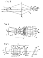
- FIG. 3 A paraxial optics layout of the display system shown in Figs. 1 and 2 is shown in Fig. 3.
- the focal length of hologram 11 must be as short as possible.
- the hologram F-number is then in the region of F/2, and the relay lens pupil (defined by the aperture stop 16) is smaller than the display exit pupil 24.
- the relay lens requirements are for a) magnification of between 1 and 2, b) an effective F-number of between 0.75 and 1.2, and c) a field angle 14 subtended by the intermediate image 15 at the relay lens exit pupil in aperture stop 16 of from 35 to 55 degrees. This is because the relay lens pupil is imaged at the display system exit pupil 24 with a magnification governed by the hologram positions and focal length.
Landscapes
- Physics & Mathematics (AREA)
- General Physics & Mathematics (AREA)
- Optics & Photonics (AREA)
- Diffracting Gratings Or Hologram Optical Elements (AREA)
- Lenses (AREA)
Description
- The invention is related to a head-up display system including a source of optical image signal, a holographic optical element, and a relay lens for forming an intermediate image of said optical image signal at the focal surface of said holographic optical element which is positioned and used as a combiner lens so that the user may see both said optical image signal projected to said holographic optical element and the external world through said holographic optical element.
- Such a head-up display system (HUD) is disclosed in the US-A-3940204. The installation of such a head-up display system in the cockpit of an airplane imposes physical restrictions which limit the available field of view. Thus, the known system has a field of view in elevation of only 15 degrees, whereas a total elevation field of view of 20 to 25 degrees is desired.
- Thus, it is an object of the present invention to provide an optical system capable of providing at least the said desirable field of view.
- According to the invention, this object is met by an improvement being characterized in that the said relay lens is comprised of seven lens elements (elements II to VIII), and that a notch bandpass filter (element IX), and a folding prism (element X) are positioned between the relay lens and the holographic optical element, so that the system comprises ten optical elements (I to X) being nubered in their order of occurence in the light path from the source (I) of optical signal and having the following prescription characteristics with regard to their surfaces numbered 51 to 69, for each surface being given the radius of curvature RD, the distance to the next surface or thickness TH, the index of refraction of the material between the surface and the next surface, and the tilt and the decentering DEC relative to an arbitrary reference line (20):

- The present invention enables the large aberrations present in the holographic optical element to be better corrected than has previously been possible. The relay lens design disclosed and claimed herein is capable of operating with a relay lens field of view of 44 degrees, while being short and extremely fast (F/0.4). These design forms permit the design of wide field of view (FOV) holographic head-up displays in which the hologram focal length is short so that the optical system is compact and can be packaged within the restricted space of an aircraft cockpit. Previous HUD designs were limited to relay lens design forms not capable of the wide FOVs and low F-numbers required for improved display configurations.
- In a preferred embodiment, the present invention consists of a 63 mm cathode ray tube image source, relay optics and a diffraction optics combining glass. The combiner not only functions as a beam splitter, but also as a collimating element for the image emanating from the CRT. The combiner consists of a diffraction optics element sandwiched between two spherical glass shells. The wavelength of light which is diffracted with highest efficiency by the combiner coincides with the narrow band P-43 phosphor emission at 543 nm.
- The display image at the CRT face or object surface is relayed via a sophisticated multi-element relay lens to an intermediate image plane at the focus of the combining element. The relay lens not only reconstructs the image at a convenient location for the combiner, but also forms a curved, tilted, and aberrated image surface in order to compensate for some aberrations introduced by the combiner. This is achieved not only by the design of the relay lens system but also by providing tilted and decentered optical elements in that system to compensate for the aberrations present in the holographic optical element combiner. The CRT can also be tilted to provide the necessary image tilt. The result is an optically corrected image of the CRT's symbology presented to the operator superimposed upon his view of the outside world. It is a characteristic feature of the new system that a majority of its optical elements are on the optical image signal source side of the aperture stop of the system and that the optical elements comprise a negative power element close to the aperture stop for control of the Petzval sum, the surface facing the intermediate image being sharply curved to avoid excessively high angles of incidence which otherwise would occur due to the wide field of view, and a positive lens group of three or more positive elements which contain most of the optical power.
- These and other objects, features and advantages of the invention will be more fully apparent to those skilled in the art from the detailed description below taken in conjunction with the accompanying drawings wherein:
- Fig. 1 is an optical schematic view taken in the plane of a vertical section through the HUD system.
- Fig. 2 is an optical schematic view taken on the line 2-2 of Fig. 1 so as to provide a horizontal section of the relay lens portion of the system.
- Fig. 3 is a paraxial optical layout of the holographic head-up display.
- Fig. 4 is the starting (rotationally symmetric) version from which the system shown in Figs. 1, 2 and 3 is derived.
- Fig. 5 is an optical schematic view showing the details of the tilting and decentering of the relay lens elements of the design shown in Figs. 1 to 4.
- The optics for a preferred example of a holographic head-up display system designed to cover a wide field of view is described by way of example with reference to the schematic diagrams of Figs. 1 to 5. The system shown therein has a field of view of 22 degrees vertical by 35 degrees horizontal and primarily consists of a
relay lens system 10 and a holographic optical element 11 which is both the combiner and collimator. The relay lens images an object surface such as therear face 51 of acathode ray tube 12 at thefocal surface 21 of the holographic optical element 11. Afolding prism 17 having a reflective rear surface is conveniently used. The holographic element subsequently forms a high quality image of the object surface which image is superimposed on the outside world as seen by the pilot observer, 0, looking through the combiner 11 and on out through theaircraft canopy 22 normally included in theairplane 13. The display can be seen by the pilot when looking through theexit pupil 24 of the display system. For good viewing conditions the exit pupil must be large and is typically located from 50 to 75 cm from the combiner. This is because the relay lens pupil defined byaperture stop 16 is imaged at the displaysystem exit pupil 24 with a magnification governed by the hologram position and focal length. Furthermore, the packaging restraints of an aircraft cockpit are very restrictive and a small cathode ray tube size is highly desirable. The resultant optical systems shown herein typically operate at speeds between F/1 and F/2. - A paraxial optics layout of the display system shown in Figs. 1 and 2 is shown in Fig. 3. To keep the optical system short and minimize the size of the
relay lens system 10, the focal length of hologram 11 must be as short as possible. The hologram F-number is then in the region of F/2, and the relay lens pupil (defined by the aperture stop 16) is smaller than thedisplay exit pupil 24. In consequence, the relay lens requirements are for a) magnification of between 1 and 2, b) an effective F-number of between 0.75 and 1.2, and c) afield angle 14 subtended by theintermediate image 15 at the relay lens exit pupil inaperture stop 16 of from 35 to 55 degrees. This is because the relay lens pupil is imaged at the displaysystem exit pupil 24 with a magnification governed by the hologram positions and focal length. - To meet these stringent requirements, a new relay lens design has been developed and is shown in schematic detail in Fig. 4. This system is the basis of that of Figs. 1 to 3 but does not yet include the tilting and decentering. The design is asymmetric to accommodate the wide field and has a majority of the optical elements on the cathode ray tube side of the
aperture stop 16. This group of elements consists of 1) negative power close to the aperture stop for control of the Petzval sum, the surface facing theintermediate image 15 being sharply curved to avoid excessively high angles of incidence which would otherwise occur due to the wide field of view, and 2) a positive lens group of positive elements which contain most of the optical power. The design also shows a curvedfocal surface 21 at the intermediate image as required to match field curvative of the hologram. - Considering again the embodiment shown in Figs. 1, 2 and 3, it will be noted that the
object surface 51 of thecathode ray tube 12 is imaged by therelay lens system 10 to form anintermediate image 15 at and coinciding with thefocal surface 21 of the holographic combiner 11 which is positioned in the line of view of the observer 0 through theaircraft canopy 22. This is facilitated by interposing afolding prism 17 in the optical path to fold or reflect the image ofobject surface 51. The folding prism can serve to also reduce the CRT tilt for ease of packaging. The optical design characteristics of this typical diffraction optics HUD is given in Table I below.
- The limitations imposed by an existing cockpit size were the driving forces in the establishment of these characteristics.
- Firstly, the CRT diameter had to be set at 88,9 mm establishing the system F-number of 1.2 corresponding the 120,40 mm diagonal of the exit pupil and the 35 degree horizontal FOV. Ejection, .canopy and cowling line clearances establish the 50
degree bend angle 25 and 245,11 mm hologram focal length. The combination of the resulting hologram F-number and the system F-number then demands a relay lens to cover 44 degree FOV at F/0.74. This is a severe requirement but illustrates the dramatic implications of the cockpit limitations on the optical design. The design requirements were further aggravated because good image quality had to be maintained over top and bottom portions of the pupil as well as the central region. The aberrations out in the corners of the pupil area are thus as important as those in the central regions being the opposite to most optical design situations in which some performance degradation at the edges of the pupil can often be tolerated. - The resulting embodiment shown in Figs. 1 and 2 shows that the relay lens design requirements led to the selection of a rather bulky, asymmetric relay lens design form, the initial rotationally symmetric form of which is shown in Fig. 4. In its rotationally symmetric form, the lens has aberrations which correspond to one or two milliradians throughout the FOV at the display exit pupil. However, when incorporated with the holographic lens and the wedged
folding mirror 17 to reduce the CRT tilt, the relay lens elements must be tilted and decentered to balance the asymmetric aberrations with some loss in performance. Good performance is obtained over the central 25 degrees but it degrades at the extremes of the 35 degree field of view. - The holographic element in a head-up display is used at a large off-axis angle and is constructed with point sources located close to the desired entrance and exit pupils to obtain high diffraction efficiency across a wide field of view. As a result, the aberrations in the holographic element are large and not suitable for correction with a rotationally symmetric relay lens because of the lack of symmetry in the hologram. To make the aberrations more amenable to correction by the relay lens the construction beams for the hologram (as taught in the prior art) are aberrated by means of cylindrical lenses in each beam. The principal aberrations are axial coma and crossed (xy) astigmatism though other significant aberrations are present. In general, these aberrations vary in an unsymmetrical fashion across the field of view. These aberrations can be corrected by the above described tilting and decentering elements in the relay lens, thus removing its rotational symmetry. The embodiment shown in Figs. 1, 2 and 3 is an example of such a design. This design has been fully tested and has proved very successful.
- Further details of the tilting and decentering of the relay lens elements are shown in Fig. 5. It will be seen that the first and last elements of the relay lens (elements II and VIII) are tilted and decentered relative to all the other relay lens elements. In addition, the first surface of the doublet (elements VI and VII) is tilted. The tilting and decentering of these elements was necessary to correct the aberrations characteristic of the off-axis holographic element.
- It will be noted by a comparison of Fig. 5 with Fig. 1 that the order of the elements from left to right is reversed in the two views. That is to say, the
object surface 51 of CRT 12 (shown in part of Fig. 5 as element I) is on the right in Fig. 1 whereas it is shown on the left in Fig. 5. It will of course be understood that the system is unaffected by whether one is looking from left to right or right to left and that symmetry in this sense is preserved. - The details of the elements shown in Fig. 5 are identified with respect to an
arbitrary reference line 20 because tilting of the lens elements prevents definition of the optical axis of the relay lens system shown in Fig. 5. It will be noted from Fig. 4 that theoptic axis 30 of the rotationally symmetric system shown therein intersects theback surface 51 of element I (which is the face plate of CRT 12) atpoint 40. In Fig. 5 thearbitrary reference line 20 intersects surface 51 at point 41. In the embodiment being described, the straight line distance betweenpoints 40 and 41 onsurface 51 was 12,32 mm. - It will be noted from Fig. 5 that the elements of the optical system are identified in the following manner. Element I is the faceplate of
cathode ray tube 12. Elements 11, III, IV, V, VI, VII and VIII are the individual glass lens components comprising therelay lens 10. Element IX is a notch bandpass filter matching the output of theCRT 12. Element X is the foldingreflective wedge 17. Element I is indicated as havingsurfaces surfaces surfaces 55 and 56 and so on as shown through Element X which hassurfaces surface 62 is common to both elements VI and VII of the doublet. The prescription data for these lens elements is set forth below in Table II. For each surface there is given the radius of curvature, the distance to the next surface or thickness, the index of refraction of the material between the surface and the next surface, the tilt and the decentering. All lenses are glass. Linear dimensions are in mm. Tilt angles are in decimal degrees.
- Holographic head-up displays also frequently require provision for a standby sight which may be incorporated via a
beam splitter 35 between the CRT and the relay lens (Fig. 4). This provides a fixed image reference pattern (which is often a reticle) for use in case the CRT fails and thus provides an image in the absence of active optical information input from the CRT. A side benefit of the use of abeam splitter prism 35 is that it may be readily tilted to introduce a large amount of axial coma, thus balancing the coma in the holographic element and reducing the amount of tilting and decentering in therelay lens system 10 and hence reducing its cost and complexity. - It is thus seen that there has been provided an improved integrated optical design for a head-up display system which simultaneously provides an improved field of view and improved means for compensating for hologram aberrations through use of tilted and decentered lenses in a novel type of relay lens systems. This in turn results in decreased size, weight and cost of the improved system.
Claims (2)

Applications Claiming Priority (2)
| Application Number | Priority Date | Filing Date | Title |
|---|---|---|---|
| US923119 | 1978-07-10 | ||
| US05/923,119 US4218111A (en) | 1978-07-10 | 1978-07-10 | Holographic head-up displays |
Publications (2)
| Publication Number | Publication Date |
|---|---|
| EP0007039A1 EP0007039A1 (en) | 1980-01-23 |
| EP0007039B1 true EP0007039B1 (en) | 1984-03-14 |
Family
ID=25448149
Family Applications (1)
| Application Number | Title | Priority Date | Filing Date |
|---|---|---|---|
| EP79102151A Expired EP0007039B1 (en) | 1978-07-10 | 1979-06-28 | Holographic head-up display system |
Country Status (3)
| Country | Link |
|---|---|
| US (1) | US4218111A (en) |
| EP (1) | EP0007039B1 (en) |
| IL (1) | IL57567A (en) |
Cited By (1)
| Publication number | Priority date | Publication date | Assignee | Title |
|---|---|---|---|---|
| FR2732479A1 (en) * | 1987-02-27 | 1996-10-04 | Thomson Csf | Head-up image or information display for aircraft or vehicle |
Families Citing this family (181)
| Publication number | Priority date | Publication date | Assignee | Title |
|---|---|---|---|---|
| US4261635A (en) * | 1978-05-16 | 1981-04-14 | Pilkington P. E. Limited | Optical apparatus |
| DE3101854A1 (en) * | 1980-01-22 | 1983-12-15 | Elliott Brothers London Ltd | VIEWING DEVICE FOR A PREVIEW DISPLAY (HEAD-UP DISPLAY) |
| US4530564A (en) * | 1980-08-18 | 1985-07-23 | Hughes Aircraft Company | Method and apparatus for production of holographic optical elements |
| GB2182159B (en) * | 1980-08-21 | 1987-10-14 | Secr Defence | Head-up displays |
| US4415239A (en) * | 1980-10-31 | 1983-11-15 | Humphrey Instruments, Inc. | Reflection rejection spherical optical train composed of tipped lens elements |
| FR2506466B1 (en) * | 1981-05-22 | 1985-07-05 | Thomson Csf | MICRO-FLAP OPTICAL FILTER, PROCESS FOR OBTAINING THE SAME, AND USE FOR AN AIRPORT CATHODE INDICATOR |
| US4372639A (en) * | 1981-06-03 | 1983-02-08 | Hughes Aircraft Company | Directional diffusing screen |
| US4603938A (en) * | 1981-11-13 | 1986-08-05 | Sony Corporation | Method of producing inline hologram lens |
| FR2533325A1 (en) * | 1982-09-21 | 1984-03-23 | Thomson Csf | HOLOGRAPHIC MIRROR VIEWING DEVICE AND MIRROR MANUFACTURING METHOD |
| FR2533684B1 (en) * | 1982-09-24 | 1986-12-19 | Thomson Csf | HIGH HEAD POINTING SIGHT USED AS SHOOTING SIGHT |
| GB2132376B (en) * | 1982-12-17 | 1986-07-30 | Ferranti Plc | Head-up display |
| US4968117A (en) * | 1983-09-02 | 1990-11-06 | Hughes Aircraft Company | Graded index asperhic combiners and display system utilizing same |
| GB2182456B (en) * | 1983-09-13 | 1987-10-14 | Secr Defence | Display systems |
| FR2589255B1 (en) * | 1983-11-16 | 1988-05-13 | Trt Telecom Radio Electr | DISTORTION-FREE SIGHT USING HOLOGRAPHIC COMPONENTS AND METHODS OF MAKING SAID HOLOGRAPHIC COMPONENTS |
| US4669810A (en) * | 1984-02-03 | 1987-06-02 | Flight Dynamics, Inc. | Head up display system |
| US5035474A (en) * | 1984-04-16 | 1991-07-30 | Hughes Aircraft Company | Biocular holographic helmet mounted display |
| US4613200A (en) * | 1984-07-09 | 1986-09-23 | Ford Motor Company | Heads-up display system with holographic dispersion correcting |
| GB2174213B (en) * | 1985-04-17 | 1988-09-07 | Gec Avionics | Head-up displays |
| IL79391A (en) * | 1985-08-14 | 1994-06-24 | Hughes Aircraft Co | Graded index aspheric combiners and display system utilizing same |
| US4730910A (en) * | 1985-09-18 | 1988-03-15 | Humphrey Instruments, Inc. | Wide angle lens system having flare rejection properties |
| US5037166A (en) * | 1985-10-07 | 1991-08-06 | Astronautics Corporation Of America | Holographic optical element for instrument panel displays |
| CA1288622C (en) * | 1985-10-07 | 1991-09-10 | Richard E. Malcolm | Holographic optical element |
| US5015049A (en) * | 1986-11-04 | 1991-05-14 | Kaiser Optical Systems | Method of forming holographic optical elements free of secondary fringes |
| US4826287A (en) * | 1987-01-20 | 1989-05-02 | Hughes Aircraft Company | Display system having coma-control plate in relay lens |
| JP2556020B2 (en) * | 1987-02-06 | 1996-11-20 | 日本電装株式会社 | Display device using hologram |
| FR2613497B1 (en) * | 1987-03-31 | 1991-08-16 | Thomson Csf | BINOCULAR, HOLOGRAPHIC AND LARGE FIELD SIGHT, USED ON HELMET |
| FR2614434B1 (en) * | 1987-04-22 | 1989-06-09 | Thomson Csf | HELMET-MOUNTED CLEAR VIEWFINDER |
| US4842389A (en) * | 1987-06-12 | 1989-06-27 | Flight Dynamics, Inc. | Vehicle display system using a holographic windshield prepared to withstand lamination process |
| US5313292A (en) * | 1987-06-12 | 1994-05-17 | Flight Dynamics | Windshield display system for an automobile |
| US5138469A (en) * | 1987-06-12 | 1992-08-11 | Flight Dynamics, Inc. | Preparation of photosensitive material to withstand a lamination process |
| US5231379A (en) * | 1987-09-18 | 1993-07-27 | Hughes Flight Dynamics, Inc. | Automobile head-up display system with apparatus for positioning source information |
| US4961625A (en) * | 1987-09-18 | 1990-10-09 | Flight Dynamics, Inc. | Automobile head-up display system with reflective aspheric surface |
| EP0393098B1 (en) * | 1987-09-18 | 1996-07-10 | Hughes Flight Dynamics, Inc. | Automobile head-up display system |
| GB8814177D0 (en) * | 1988-06-15 | 1988-07-20 | Marconi Gec Ltd | Head-up display systems |
| US4998784A (en) * | 1988-08-31 | 1991-03-12 | Ppg Industries, Inc. | Automotive windshield for a head up display system |
| GB8822731D0 (en) * | 1988-09-28 | 1988-11-02 | Secr Defence | Head-up display |
| US5162928A (en) * | 1988-11-02 | 1992-11-10 | Canon Kabushiki Kaisha | Head-up display apparatus |
| JPH02124515A (en) * | 1988-11-02 | 1990-05-11 | Canon Inc | display device |
| US5880888A (en) * | 1989-01-23 | 1999-03-09 | Hughes Aircraft Company | Helmet mounted display system |
| US4969714A (en) * | 1989-02-21 | 1990-11-13 | United Technologies Corporation | Helmet mounted display having dual interchangeable optical eyepieces |
| US4973139A (en) * | 1989-04-07 | 1990-11-27 | Hughes Aircraft Company | Automotive head-up display |
| US4968123A (en) * | 1989-04-24 | 1990-11-06 | United Technologies Corporation | Helmet mounted display configured for simulator use |
| US5013135A (en) * | 1989-07-10 | 1991-05-07 | Matsushita Electric Industrial Co., Ltd. | Head-up display with two fresnel lenses |
| JP2705245B2 (en) * | 1989-09-27 | 1998-01-28 | キヤノン株式会社 | Head-up display device |
| JP2653186B2 (en) * | 1989-09-27 | 1997-09-10 | キヤノン株式会社 | Head-up display device |
| US5812332A (en) * | 1989-09-28 | 1998-09-22 | Ppg Industries, Inc. | Windshield for head-up display system |
| JP3141081B2 (en) * | 1990-08-10 | 2001-03-05 | 矢崎総業株式会社 | Display device for vehicles |
| GB9116108D0 (en) * | 1991-07-25 | 1991-11-06 | Pilkington Perkin Elmer Ltd | Improvements in or relating to displays |
| US5257133A (en) * | 1991-09-11 | 1993-10-26 | Hughes Aircraft Company | Re-imaging optical system employing refractive and diffractive optical elements |
| JP2801461B2 (en) * | 1992-03-25 | 1998-09-21 | キヤノン株式会社 | Shift optical system and optical apparatus having the same |
| US5305124A (en) * | 1992-04-07 | 1994-04-19 | Hughes Aircraft Company | Virtual image display system |
| US5357372A (en) * | 1992-04-07 | 1994-10-18 | Hughes Aircraft Company | Ultra-compact, wide field of view virtual image display optical system |
| US5278696A (en) * | 1992-05-22 | 1994-01-11 | Kaiser Aerospace & Electronics Corporation | Head-up display system |
| EP0574005A2 (en) * | 1992-06-12 | 1993-12-15 | Canon Kabushiki Kaisha | Hologram lens and display apparatus using the same |
| JP3155360B2 (en) * | 1992-07-27 | 2001-04-09 | オリンパス光学工業株式会社 | Visual display device |
| US5585813A (en) * | 1992-10-05 | 1996-12-17 | Rockwell International Corporation | All aspect head aiming display |
| US5299063A (en) * | 1992-11-10 | 1994-03-29 | Honeywell, Inc. | Cross projection visor helmet mounted display |
| US5537253A (en) * | 1993-02-01 | 1996-07-16 | Honeywell Inc. | Head mounted display utilizing diffractive optical elements |
| JP3212203B2 (en) * | 1993-02-09 | 2001-09-25 | オリンパス光学工業株式会社 | Visual display device |
| GB9304944D0 (en) * | 1993-03-11 | 1993-04-28 | Pilkington Perkin Elmer Ltd | Head-up displays |
| US5384654A (en) * | 1993-05-10 | 1995-01-24 | Olympus Optical Co., Ltd. | Image observation device |
| US5499139A (en) * | 1993-10-01 | 1996-03-12 | Hughes Aircraft Company | Ultra-wide field of view, broad spectral band helmet visor display optical system |
| US5526183A (en) * | 1993-11-29 | 1996-06-11 | Hughes Electronics | Helmet visor display employing reflective, refractive and diffractive optical elements |
| JP3392929B2 (en) * | 1994-02-07 | 2003-03-31 | オリンパス光学工業株式会社 | Video display device |
| US5867287A (en) * | 1994-09-30 | 1999-02-02 | Hughes Aircraft Company | Head up display with a lens decentered to the optical axis of the illumination |
| US5793450A (en) * | 1994-11-10 | 1998-08-11 | Grumman Aerospace Corporation | Canopy transmittal reflectance control and information display |
| AU4013597A (en) | 1996-08-06 | 1998-02-25 | Konstantin Roggatz | Holographic system for large image production |
| US6204974B1 (en) | 1996-10-08 | 2001-03-20 | The Microoptical Corporation | Compact image display system for eyeglasses or other head-borne frames |
| US5886822A (en) * | 1996-10-08 | 1999-03-23 | The Microoptical Corporation | Image combining system for eyeglasses and face masks |
| US6023372A (en) * | 1997-10-30 | 2000-02-08 | The Microoptical Corporation | Light weight, compact remountable electronic display device for eyeglasses or other head-borne eyewear frames |
| WO1999023524A1 (en) | 1997-10-30 | 1999-05-14 | The Microoptical Corporation | Eyeglass interface system |
| JP3338837B2 (en) * | 1997-12-10 | 2002-10-28 | キヤノン株式会社 | Composite display |
| US6724354B1 (en) | 1999-06-21 | 2004-04-20 | The Microoptical Corporation | Illumination systems for eyeglass and facemask display systems |
| CA2377742A1 (en) | 1999-06-21 | 2000-12-28 | The Microoptical Corporation | Compact, head-mountable display device with suspended eyepiece assembly |
| WO2000079327A1 (en) | 1999-06-21 | 2000-12-28 | The Microoptical Corporation | Eyeglass display lens system employing off-axis optical design |
| US7158096B1 (en) | 1999-06-21 | 2007-01-02 | The Microoptical Corporation | Compact, head-mountable display device with suspended eyepiece assembly |
| US6466371B1 (en) * | 2000-01-26 | 2002-10-15 | Aerial Imaging Corporation | Diffractive lens with gratings modified to offset effects caused by holding the lens at an angle with respect to a light source |
| US6612840B1 (en) * | 2000-04-28 | 2003-09-02 | L-3 Communications Corporation | Head-up display simulator system |
| FR2818393B1 (en) * | 2000-12-19 | 2003-10-10 | Thomson Csf | METHOD FOR MANUFACTURING A SET OF HIGH HEAD SIGHTS ADAPTED TO DATA TYPE EQUIPMENT |
| WO2003023756A1 (en) * | 2001-09-07 | 2003-03-20 | The Microoptical Corporation | Light weight, compact, remountable face-supported electronic display |
| DE10144491C2 (en) * | 2001-09-10 | 2003-08-21 | Siemens Ag | Head up display with adjustment device for a mirror |
| US7313246B2 (en) * | 2001-10-06 | 2007-12-25 | Stryker Corporation | Information system using eyewear for communication |
| US7056119B2 (en) * | 2001-11-29 | 2006-06-06 | Lsa, Inc. | Periscopic optical training system for operators of vehicles |
| US7619825B1 (en) | 2004-09-27 | 2009-11-17 | Rockwell Collins, Inc. | Compact head up display with wide viewing angle |
| IL168581A (en) * | 2005-05-15 | 2010-12-30 | Elbit Systems Electro Optics Elop Ltd | Head-up display system |
| US7513668B1 (en) | 2005-08-04 | 2009-04-07 | Rockwell Collins, Inc. | Illumination system for a head up display |
| US7397606B1 (en) | 2005-08-04 | 2008-07-08 | Rockwell Collins, Inc. | Meniscus head up display combiner |
| GB0718706D0 (en) | 2007-09-25 | 2007-11-07 | Creative Physics Ltd | Method and apparatus for reducing laser speckle |
| RU2353958C1 (en) * | 2007-12-10 | 2009-04-27 | Федеральное государственное унитарное предприятие "Научно-производственная корпорация "Государственный оптический институт им. С.И. Вавилова" (ФГУП "НПК "ГОИ им. Вавилова") | Optical system of helmet-mounted collimator display |
| DE102008059892A1 (en) * | 2008-12-02 | 2010-06-10 | Carl Zeiss Sports Optics Gmbh | Device for inserting an image into the beam path of a target optics |
| US9335604B2 (en) | 2013-12-11 | 2016-05-10 | Milan Momcilo Popovich | Holographic waveguide display |
| US11726332B2 (en) | 2009-04-27 | 2023-08-15 | Digilens Inc. | Diffractive projection apparatus |
| US8299938B2 (en) * | 2009-09-08 | 2012-10-30 | Rosemount Inc. | Projected instrument displays for field mounted process instruments |
| US8233204B1 (en) | 2009-09-30 | 2012-07-31 | Rockwell Collins, Inc. | Optical displays |
| US11300795B1 (en) | 2009-09-30 | 2022-04-12 | Digilens Inc. | Systems for and methods of using fold gratings coordinated with output couplers for dual axis expansion |
| US11320571B2 (en) | 2012-11-16 | 2022-05-03 | Rockwell Collins, Inc. | Transparent waveguide display providing upper and lower fields of view with uniform light extraction |
| US10795160B1 (en) | 2014-09-25 | 2020-10-06 | Rockwell Collins, Inc. | Systems for and methods of using fold gratings for dual axis expansion |
| US8659826B1 (en) | 2010-02-04 | 2014-02-25 | Rockwell Collins, Inc. | Worn display system and method without requiring real time tracking for boresight precision |
| US7982959B1 (en) | 2010-08-02 | 2011-07-19 | Matvey Lvovskiy | Head-up display |
| US9274349B2 (en) | 2011-04-07 | 2016-03-01 | Digilens Inc. | Laser despeckler based on angular diversity |
| EP2995986B1 (en) | 2011-08-24 | 2017-04-12 | Rockwell Collins, Inc. | Data display |
| US10670876B2 (en) | 2011-08-24 | 2020-06-02 | Digilens Inc. | Waveguide laser illuminator incorporating a despeckler |
| WO2016020630A2 (en) | 2014-08-08 | 2016-02-11 | Milan Momcilo Popovich | Waveguide laser illuminator incorporating a despeckler |
| US8937772B1 (en) | 2011-09-30 | 2015-01-20 | Rockwell Collins, Inc. | System for and method of stowing HUD combiners |
| US8903207B1 (en) | 2011-09-30 | 2014-12-02 | Rockwell Collins, Inc. | System for and method of extending vertical field of view in head up display utilizing a waveguide combiner |
| US9599813B1 (en) | 2011-09-30 | 2017-03-21 | Rockwell Collins, Inc. | Waveguide combiner system and method with less susceptibility to glare |
| US9715067B1 (en) | 2011-09-30 | 2017-07-25 | Rockwell Collins, Inc. | Ultra-compact HUD utilizing waveguide pupil expander with surface relief gratings in high refractive index materials |
| US8749890B1 (en) * | 2011-09-30 | 2014-06-10 | Rockwell Collins, Inc. | Compact head up display (HUD) for cockpits with constrained space envelopes |
| US9366864B1 (en) | 2011-09-30 | 2016-06-14 | Rockwell Collins, Inc. | System for and method of displaying information without need for a combiner alignment detector |
| US8634139B1 (en) | 2011-09-30 | 2014-01-21 | Rockwell Collins, Inc. | System for and method of catadioptric collimation in a compact head up display (HUD) |
| US11640050B2 (en) | 2011-10-19 | 2023-05-02 | Epic Optix Inc. | Microdisplay-based head-up display system |
| WO2013102759A2 (en) | 2012-01-06 | 2013-07-11 | Milan Momcilo Popovich | Contact image sensor using switchable bragg gratings |
| US8830588B1 (en) | 2012-03-28 | 2014-09-09 | Rockwell Collins, Inc. | Reflector and cover glass for substrate guided HUD |
| US9523852B1 (en) | 2012-03-28 | 2016-12-20 | Rockwell Collins, Inc. | Micro collimator system and method for a head up display (HUD) |
| ITTO20120367A1 (en) * | 2012-04-24 | 2013-10-25 | Selex Galileo Spa | UNIT OF GENERATION AND PROJECTION OF VISUAL INFORMATION FOR IMAGE VISUALIZATION SYSTEMS WITH INFINITE FIRE, IN PARTICULAR FOR HIGH HEAD VISUALIZATION SYSTEMS |
| WO2013163347A1 (en) | 2012-04-25 | 2013-10-31 | Rockwell Collins, Inc. | Holographic wide angle display |
| CN103513420A (en) * | 2012-06-27 | 2014-01-15 | 北京理工大学 | Vehicle-mounted head-up display projection collimation relay optics system based on holographic optical element |
| US9933684B2 (en) | 2012-11-16 | 2018-04-03 | Rockwell Collins, Inc. | Transparent waveguide display providing upper and lower fields of view having a specific light output aperture configuration |
| US9674413B1 (en) | 2013-04-17 | 2017-06-06 | Rockwell Collins, Inc. | Vision system and method having improved performance and solar mitigation |
| US9341850B1 (en) | 2013-04-30 | 2016-05-17 | Google Inc. | Diffractive see-through display with hybrid-optical aberration compensation |
| US9442291B1 (en) | 2013-06-28 | 2016-09-13 | Google Inc. | Segmented diffractive optical elements for a head wearable display |
| US9727772B2 (en) | 2013-07-31 | 2017-08-08 | Digilens, Inc. | Method and apparatus for contact image sensing |
| US9244281B1 (en) | 2013-09-26 | 2016-01-26 | Rockwell Collins, Inc. | Display system and method using a detached combiner |
| US9459455B2 (en) | 2013-12-19 | 2016-10-04 | Google Inc. | See-through eyepiece for head wearable display |
| US9389422B1 (en) | 2013-12-23 | 2016-07-12 | Google Inc. | Eyepiece for head wearable display using partial and total internal reflections |
| US10732407B1 (en) | 2014-01-10 | 2020-08-04 | Rockwell Collins, Inc. | Near eye head up display system and method with fixed combiner |
| US9519089B1 (en) | 2014-01-30 | 2016-12-13 | Rockwell Collins, Inc. | High performance volume phase gratings |
| JP2017078725A (en) * | 2014-02-19 | 2017-04-27 | 株式会社 ニコンビジョン | Variable power optical system |
| US9395544B2 (en) | 2014-03-13 | 2016-07-19 | Google Inc. | Eyepiece with switchable reflector for head wearable display |
| US9244280B1 (en) | 2014-03-25 | 2016-01-26 | Rockwell Collins, Inc. | Near eye display system and method for display enhancement or redundancy |
| US9915823B1 (en) | 2014-05-06 | 2018-03-13 | Google Llc | Lightguide optical combiner for head wearable display |
| US10359736B2 (en) | 2014-08-08 | 2019-07-23 | Digilens Inc. | Method for holographic mastering and replication |
| US10539791B2 (en) | 2014-09-02 | 2020-01-21 | Ostendo Technologies, Inc. | Split exit pupil multiple virtual image heads-up display systems and methods |
| US9494794B2 (en) | 2014-09-02 | 2016-11-15 | Ostendo Technologies, Inc. | Split exit pupil heads-up display systems and methods |
| US10241330B2 (en) | 2014-09-19 | 2019-03-26 | Digilens, Inc. | Method and apparatus for generating input images for holographic waveguide displays |
| US9715110B1 (en) | 2014-09-25 | 2017-07-25 | Rockwell Collins, Inc. | Automotive head up display (HUD) |
| US10088675B1 (en) | 2015-05-18 | 2018-10-02 | Rockwell Collins, Inc. | Turning light pipe for a pupil expansion system and method |
| US9507151B2 (en) | 2014-10-10 | 2016-11-29 | The Boeing Company | Optical design of a wide field of view pupil forming HUD |
| US9366869B2 (en) | 2014-11-10 | 2016-06-14 | Google Inc. | Thin curved eyepiece for see-through head wearable display |
| EP3245444B1 (en) | 2015-01-12 | 2021-09-08 | DigiLens Inc. | Environmentally isolated waveguide display |
| US9632226B2 (en) | 2015-02-12 | 2017-04-25 | Digilens Inc. | Waveguide grating device |
| RU2582210C1 (en) * | 2015-03-03 | 2016-04-20 | Открытое акционерное общество "ЛОМО" | Optical system for onboard projector indicator |
| US9291821B1 (en) | 2015-03-05 | 2016-03-22 | Matvey Lvovskiy | Wide-angle head-up display with three-component combiner |
| US10126552B2 (en) | 2015-05-18 | 2018-11-13 | Rockwell Collins, Inc. | Micro collimator system and method for a head up display (HUD) |
| US10247943B1 (en) | 2015-05-18 | 2019-04-02 | Rockwell Collins, Inc. | Head up display (HUD) using a light pipe |
| US11366316B2 (en) | 2015-05-18 | 2022-06-21 | Rockwell Collins, Inc. | Head up display (HUD) using a light pipe |
| US10162180B2 (en) | 2015-06-04 | 2018-12-25 | Google Llc | Efficient thin curved eyepiece for see-through head wearable display |
| US10108010B2 (en) | 2015-06-29 | 2018-10-23 | Rockwell Collins, Inc. | System for and method of integrating head up displays and head down displays |
| US10146054B2 (en) | 2015-07-06 | 2018-12-04 | Google Llc | Adding prescriptive correction to eyepieces for see-through head wearable displays |
| CN113759555B (en) | 2015-10-05 | 2024-09-20 | 迪吉伦斯公司 | Waveguide Display |
| US10598932B1 (en) | 2016-01-06 | 2020-03-24 | Rockwell Collins, Inc. | Head up display for integrating views of conformally mapped symbols and a fixed image source |
| WO2017162999A1 (en) | 2016-03-24 | 2017-09-28 | Popovich Milan Momcilo | Method and apparatus for providing a polarization selective holographic waveguide device |
| US10890707B2 (en) | 2016-04-11 | 2021-01-12 | Digilens Inc. | Holographic waveguide apparatus for structured light projection |
| US10845591B2 (en) | 2016-04-12 | 2020-11-24 | Ostendo Technologies, Inc. | Split exit pupil heads-up display systems and methods |
| CN106534815A (en) * | 2016-11-11 | 2017-03-22 | 中国航空工业集团公司洛阳电光设备研究所 | Electric compensation method of large view filed off-axis digital HUD image source and optical system installation and adjustment precision |
| EP3548939A4 (en) | 2016-12-02 | 2020-11-25 | DigiLens Inc. | WAVE GUIDE DEVICE WITH UNIFORM OUTPUT LIGHTING |
| WO2018129398A1 (en) | 2017-01-05 | 2018-07-12 | Digilens, Inc. | Wearable heads up displays |
| US10295824B2 (en) | 2017-01-26 | 2019-05-21 | Rockwell Collins, Inc. | Head up display with an angled light pipe |
| JP7025439B2 (en) | 2017-03-03 | 2022-02-24 | オステンド・テクノロジーズ・インコーポレーテッド | Split exit pupil head-up display system and method |
| US10942430B2 (en) | 2017-10-16 | 2021-03-09 | Digilens Inc. | Systems and methods for multiplying the image resolution of a pixelated display |
| KR102568792B1 (en) * | 2017-12-04 | 2023-08-21 | 삼성전자주식회사 | Multi-image display apparatus including diffractive optical element |
| KR20250004154A (en) | 2018-01-08 | 2025-01-07 | 디지렌즈 인코포레이티드. | Methods for fabricating optical waveguides |
| US20190212588A1 (en) | 2018-01-08 | 2019-07-11 | Digilens, Inc. | Systems and Methods for Manufacturing Waveguide Cells |
| US10914950B2 (en) | 2018-01-08 | 2021-02-09 | Digilens Inc. | Waveguide architectures and related methods of manufacturing |
| US10732569B2 (en) | 2018-01-08 | 2020-08-04 | Digilens Inc. | Systems and methods for high-throughput recording of holographic gratings in waveguide cells |
| WO2020023779A1 (en) | 2018-07-25 | 2020-01-30 | Digilens Inc. | Systems and methods for fabricating a multilayer optical structure |
| KR102766549B1 (en) | 2018-12-12 | 2025-02-12 | 삼성전자주식회사 | Head up display device providing three dimensional augmented reality |
| WO2020149956A1 (en) | 2019-01-14 | 2020-07-23 | Digilens Inc. | Holographic waveguide display with light control layer |
| US20200247017A1 (en) | 2019-02-05 | 2020-08-06 | Digilens Inc. | Methods for Compensating for Optical Surface Nonuniformity |
| US20220283377A1 (en) | 2019-02-15 | 2022-09-08 | Digilens Inc. | Wide Angle Waveguide Display |
| CN113692544B (en) | 2019-02-15 | 2025-04-22 | 迪吉伦斯公司 | Method and apparatus for providing holographic waveguide displays using integrated gratings |
| US20200292745A1 (en) | 2019-03-12 | 2020-09-17 | Digilens Inc. | Holographic Waveguide Backlight and Related Methods of Manufacturing |
| CN114207492A (en) | 2019-06-07 | 2022-03-18 | 迪吉伦斯公司 | Waveguide with transmission grating and reflection grating and method for producing the same |
| US11681143B2 (en) | 2019-07-29 | 2023-06-20 | Digilens Inc. | Methods and apparatus for multiplying the image resolution and field-of-view of a pixelated display |
| KR102775783B1 (en) | 2019-08-29 | 2025-02-28 | 디지렌즈 인코포레이티드. | Vacuum grid and method for manufacturing the same |
| US11268860B2 (en) | 2020-07-24 | 2022-03-08 | Raytheon Company | Radiometric calibration of detector |
| CN112213859B (en) | 2020-10-12 | 2022-09-23 | 歌尔科技有限公司 | Head-mounted display device and imaging method thereof |
| WO2022150841A1 (en) | 2021-01-07 | 2022-07-14 | Digilens Inc. | Grating structures for color waveguides |
| EP4288831A4 (en) | 2021-03-05 | 2025-01-15 | Digilens Inc. | EVACUATED PERIODIC STRUCTURES AND THEIR MANUFACTURING PROCESSES |
| CN115373204A (en) * | 2021-05-20 | 2022-11-22 | 华为技术有限公司 | Projection system, augmented reality glasses, vehicle and terminal |
| WO2023007230A1 (en) * | 2021-07-30 | 2023-02-02 | Wayray Ag | Compact holographic head-up display device |
Family Cites Families (13)
| Publication number | Priority date | Publication date | Assignee | Title |
|---|---|---|---|---|
| US3378326A (en) * | 1963-09-12 | 1968-04-16 | Bell & Howell Co | Gyroscopically controlled accidental motion compensator for optical instruments |
| GB1097012A (en) * | 1964-03-20 | 1967-12-29 | Elliott Brothers London Ltd | Optical systems for superimposing displays upon scenes viewed through curved windows |
| US3533104A (en) * | 1968-05-17 | 1970-10-06 | Ibm | Head-up display system |
| US3593259A (en) * | 1968-11-25 | 1971-07-13 | Singer General Precision | Alpha-gamma flight path display |
| US3737212A (en) * | 1970-12-14 | 1973-06-05 | Gen Electric | Diffraction optics head up display |
| US3697154A (en) * | 1971-05-12 | 1972-10-10 | Us Navy | Optical viewing system |
| US3885095A (en) * | 1973-04-30 | 1975-05-20 | Hughes Aircraft Co | Combined head-up multisensor display |
| US3807829A (en) * | 1973-04-30 | 1974-04-30 | Hughes Aircraft Co | Extended-field holographic lens arrays |
| US3915548A (en) * | 1973-04-30 | 1975-10-28 | Hughes Aircraft Co | Holographic lens and liquid crystal image source for head-up display |
| US4018512A (en) * | 1973-11-09 | 1977-04-19 | Fuji Photo Optical Co., Ltd. | Retrofocus type lens |
| US3949490A (en) * | 1974-10-25 | 1976-04-13 | The United States Of America As Represented By The Secretary Of The Navy | Simulator including improved holographic heads up display system |
| US3945716A (en) * | 1974-12-20 | 1976-03-23 | The United States Of America As Represented By The Secretary Of The Navy | Rotatable head up display with coordinate reversal correctives |
| US3940204A (en) * | 1975-01-23 | 1976-02-24 | Hughes Aircraft Company | Optical display systems utilizing holographic lenses |
-
1978
- 1978-07-10 US US05/923,119 patent/US4218111A/en not_active Expired - Lifetime
-
1979
- 1979-06-14 IL IL57567A patent/IL57567A/en unknown
- 1979-06-28 EP EP79102151A patent/EP0007039B1/en not_active Expired
Cited By (1)
| Publication number | Priority date | Publication date | Assignee | Title |
|---|---|---|---|---|
| FR2732479A1 (en) * | 1987-02-27 | 1996-10-04 | Thomson Csf | Head-up image or information display for aircraft or vehicle |
Also Published As
| Publication number | Publication date |
|---|---|
| EP0007039A1 (en) | 1980-01-23 |
| IL57567A (en) | 1981-12-31 |
| US4218111A (en) | 1980-08-19 |
Similar Documents
| Publication | Publication Date | Title |
|---|---|---|
| US4218111A (en) | Holographic head-up displays | |
| US5035474A (en) | Biocular holographic helmet mounted display | |
| US3940204A (en) | Optical display systems utilizing holographic lenses | |
| JP2705880B2 (en) | Broad spectrum band virtual image display optical system | |
| EP0672265B1 (en) | Ultra-wide field of view, broad spectral band helmet visor display optical system | |
| US5880888A (en) | Helmet mounted display system | |
| EP0298119B1 (en) | Coma-control plate in relay lens | |
| EP0834097B1 (en) | Head gear display system | |
| US5526183A (en) | Helmet visor display employing reflective, refractive and diffractive optical elements | |
| US4854688A (en) | Optical arrangement | |
| EP1303782B1 (en) | High brightness see-through head-mounted display | |
| US4383740A (en) | Infinity image visual display system | |
| EP0660155B1 (en) | Image display apparatus | |
| US5652679A (en) | Optical systems, telescopes and binoculars | |
| KR0128267B1 (en) | Virtual display optical system of ultra-compact optical clock | |
| EP0179124B1 (en) | Binocular holographic helmet mounted display | |
| US20030020006A1 (en) | Planar diffractive relay | |
| JPS61194421A (en) | Optical apparatus for supply of display image | |
| US4993788A (en) | Head-up display systems | |
| JP3245472B2 (en) | Head mounted display | |
| US4801183A (en) | Infra-red optical systems | |
| JPH06250114A (en) | Video display device | |
| SE507815C2 (en) | Binocular image amplifier binoculars | |
| GB2295026A (en) | Off axis projection optics for head mounted display |
Legal Events
| Date | Code | Title | Description |
|---|---|---|---|
| PUAI | Public reference made under article 153(3) epc to a published international application that has entered the european phase |
Free format text: ORIGINAL CODE: 0009012 |
|
| AK | Designated contracting states |
Designated state(s): FR GB IT SE |
|
| 17P | Request for examination filed | ||
| ITF | It: translation for a ep patent filed | ||
| GRAA | (expected) grant |
Free format text: ORIGINAL CODE: 0009210 |
|
| AK | Designated contracting states |
Designated state(s): FR GB IT SE |
|
| ET | Fr: translation filed | ||
| PLBE | No opposition filed within time limit |
Free format text: ORIGINAL CODE: 0009261 |
|
| STAA | Information on the status of an ep patent application or granted ep patent |
Free format text: STATUS: NO OPPOSITION FILED WITHIN TIME LIMIT |
|
| 26N | No opposition filed | ||
| ITTA | It: last paid annual fee | ||
| EAL | Se: european patent in force in sweden |
Ref document number: 79102151.2 |
|
| PGFP | Annual fee paid to national office [announced via postgrant information from national office to epo] |
Ref country code: FR Payment date: 19970510 Year of fee payment: 19 |
|
| PGFP | Annual fee paid to national office [announced via postgrant information from national office to epo] |
Ref country code: SE Payment date: 19970520 Year of fee payment: 19 Ref country code: GB Payment date: 19970520 Year of fee payment: 19 |
|
| PG25 | Lapsed in a contracting state [announced via postgrant information from national office to epo] |
Ref country code: GB Free format text: LAPSE BECAUSE OF NON-PAYMENT OF DUE FEES Effective date: 19980628 |
|
| PG25 | Lapsed in a contracting state [announced via postgrant information from national office to epo] |
Ref country code: SE Free format text: LAPSE BECAUSE OF NON-PAYMENT OF DUE FEES Effective date: 19980629 |
|
| GBPC | Gb: european patent ceased through non-payment of renewal fee |
Effective date: 19980628 |
|
| PG25 | Lapsed in a contracting state [announced via postgrant information from national office to epo] |
Ref country code: FR Free format text: LAPSE BECAUSE OF NON-PAYMENT OF DUE FEES Effective date: 19990226 |
|
| EUG | Se: european patent has lapsed |
Ref document number: 79102151.2 |
|
| REG | Reference to a national code |
Ref country code: FR Ref legal event code: ST |