EP0006807B1 - Arrangement for a multiplexed hertzian channel - Google Patents
Arrangement for a multiplexed hertzian channel Download PDFInfo
- Publication number
- EP0006807B1 EP0006807B1 EP79400409A EP79400409A EP0006807B1 EP 0006807 B1 EP0006807 B1 EP 0006807B1 EP 79400409 A EP79400409 A EP 79400409A EP 79400409 A EP79400409 A EP 79400409A EP 0006807 B1 EP0006807 B1 EP 0006807B1
- Authority
- EP
- European Patent Office
- Prior art keywords
- frequency
- transmitter
- operator
- mhz
- low
- Prior art date
- Legal status (The legal status is an assumption and is not a legal conclusion. Google has not performed a legal analysis and makes no representation as to the accuracy of the status listed.)
- Expired
Links
Images

Classifications
-
- H—ELECTRICITY
- H04—ELECTRIC COMMUNICATION TECHNIQUE
- H04B—TRANSMISSION
- H04B7/00—Radio transmission systems, i.e. using radiation field
- H04B7/24—Radio transmission systems, i.e. using radiation field for communication between two or more posts
Definitions
- the present invention relates to a multiplex radio link device. It finds a general application in telecommunications and a particular application in the realization of means of phonic communication between several people distant from each other, or isolated from each other by the fact that they are covered with waterproof suits, which is the This is particularly the case for people working in hostile environments and, in particular, in decontamination chambers for radioactive objects and materials.
- the wire connection devices are generally not satisfactory in this application, due to the permanent risks of cutting the wires, and the poor quality of the connection.
- a wireless link system is used, by radio wave.
- Such a system is composed of a set of transceiver stations, each operator having at his disposal such a station, hereinafter called operator station, and the person located outside the enclosure having another post then said post-director.
- operator station each operator having at his disposal such a station
- manager station the person located outside the enclosure having another post then said post-director.
- each of the communication channels established between an operator station and the manager station can be carried out on a particular frequency, in order to avoid interference between messages originating from several operators. We then obtain a frequency multiplexed system.
- the manager station be equipped with as many receivers as there are operator stations, each of said receivers working on a particular frequency; the station manager can be fitted with as many transmitters as there are operator stations, but it is also possible to use only one transmitter, the receivers of the operator stations then being all identical.
- the subject of the invention is precisely a device of the type described, but which also gives operators the possibility of communicating between them without the need to add additional means to the operator stations.
- the device of the invention De requires on the part of said operators no manipulation of switching members, in particular during the passages between a reception phase and a transmission phase.
- the subject of the present invention is a frequency-multiplexed radio link device between a manager and at least two operator stations, this device being of the type in which the manager includes, on the one hand, a transmitter receiving a low frequency signal from a microphone and emitting a high frequency wave Fe and, on the other hand, as many receivers as there are operator stations, each receiver being tuned to a high frequency particular Fi different from Fe, each receiver delivering a low frequency signal which is directed towards a loudspeaker, and in which each post-operator comprises, on the one hand, a receiver calibrated on said frequency Fe and feeding a loudspeaker and, on the other hand, a transmitter connected to a microphone and operating on one of said frequencies Fi, characterized in that the director station comprises a transmitter consisting of a low frequency preamplification stage connected to the microph one then modulation and amplification means connected to an antenna and in that it further comprises means for taking a portion of the low frequency signals delivered by each of the receivers of this manager and re-injecting these
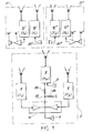
- Figure 1 refers by way of explanation to the particular case where the number of these operator positions is equal to two.
- the device shown comprises two operator stations P 'and P "and a director station P.
- the latter comprises, on the one hand, a transmitter 2 which receives a low frequency signal from a microphone 3 and which emits a wave at high frequency Fe and, on the other hand, two receivers 4 and 6 calibrated respectively on high frequencies F 1 and F 2 different from Fe and each delivering a signal at low frequency directed towards a loudspeaker 8 through an amplifier circuit 10.
- Each operator station P 'and P “comprises, on the one hand, a receiver 12'(12") calibrated on the frequency Fe and supplying a loudspeaker 14 '(14 ") via an amplifier 16 '(16 ") and, on the other hand, a transmitter 18'(18") connected to a microphone 20 '(20 "); the transmitters 18 'and 18 "operate respectively on the frequencies F i and F Z.
- the device shown further comprises, and according to the invention, means located in the director station P for reinjecting a portion of the low frequency signals delivered by each of the receivers 4 and 6 of the director station in the transmitter 2 of this post.
- these means consist of a resistive bridge formed by two resistances 22 and 24 whose midpoint 26 is connected to the low frequency amplifier circuit 10.
- Each operator with a P 'or P "station can establish a phonic connection with the person with the P-director station.
- the means involved in such a connection are, on the outward journey: the transmitter 18' (or 18 ") operating on frequency F 1 (or F 2 ), receiver 4 (frequency F i ) or receiver 6 (frequency F Z ); and on return: the transmitter 2 of the director station P and the receiver 12 '(or 12 ").
- the communication between two operators with P 'and P "stations respectively takes place through the channel of the P director station thanks to the reinjection into the transmitter 2 of the low frequency signals delivered by the two receivers 4 and 6.
- FIG. 2 first of all, illustrates the block diagram of a transmitter circuit.
- a transmitter circuit comprises, connected to a microphone 30, a low frequency amplifier 32, a potentiometer 34, an oscillator 36 controlled by quartz, a frequency mixer 38, followed by a frequency discriminator 40, connected to an oscillator 42 modulated in frequency and finally a high frequency amplifier 44 coupled to an antenna 46.
- this transmitter is incorporated in the director station, it further comprises a resistive bridge 48 whose input is connected to the receiver of said station by connection 76 so that the low frequency signals delivered by these receivers are reinjected with the low frequency signal delivered by the amplifier 32 in the circuit 42 belonging to the transmission stage.
- the illustrated circuit comprises, after an antenna 50, a high frequency amplifier 52, a first frequency mixer 54, followed by an intermediate frequency amplifier 56 , itself followed by a second frequency mixer circuit 58, which receives, from a local oscillator 60 controlled by quartz, a signal. which is also applied to a frequency multiplier circuit 62, the output of which is applied to the first mixer circuit 54.
- An amplitude detection circuit 64 makes it possible to supply a loop 66 of automatic gain control.
- the circuit is completed by a medium frequency amplifier and limiter 68 connected to a circuit 70 for discrimination and de-emphasis, connected to a low frequency amplifier 72 which controls a loudspeaker 74.
- connection 76 is provided after the low frequency amplification circuit 72, to allow the reinjection of part of the low signal frequency in the transmission circuit, connection 76 which is found in the diagram in FIG. 2, as indicated above.
- the frequencies 32.8 MHz-36.4 MHz and 39.2 MHz are authorized in France by the Administration of Posts and Telecommunications, namely the frequencies 32.8 MHz-36.4 MHz and 39.2 MHz.
- the transmitter of the director station is then calibrated for example on 32.8 MHz
- the two receivers of the secondary stations are also calibrated on these frequencies
- one of the transmitters of the secondary stations is calibrated on 36.4 MHz and the second on 39.2 MHz.
- the two receivers of the control station are tuned respectively on the frequencies 36.4 and 39.2 MHz.
Description
La présente invention a pour objet un dispositif de liaison hertzienne multiplexée. Elle trouve une application générale en télécommunications et une application particulière dans la réalisation de moyens de communication phonique entre plusieurs personnes éloignées les unes des autres, ou isolées les unes des autres par le fait qu'elles sont revêtues de combinaisons étanches, ce qui est le cas notamment des personnes travaillant en milieu hostile et, en particulier, dans des enceintes de décontamination d'objets et matières radioactifs.The present invention relates to a multiplex radio link device. It finds a general application in telecommunications and a particular application in the realization of means of phonic communication between several people distant from each other, or isolated from each other by the fact that they are covered with waterproof suits, which is the This is particularly the case for people working in hostile environments and, in particular, in decontamination chambers for radioactive objects and materials.
Les opérateurs qui travaillent dans de telles enceintes sont équipés de vêtements ventilés qui les isolent entièrement du milieu ambiant. Ces conditions particulières de travail nécessitent, autant pour des raisons de sécurité que d'efficacité et de confort, l'emploi de moyens de communication entre les opérateurs et des personnes situées à l'extérieur de l'enceinte.Operators working in such enclosures are equipped with ventilated clothing which completely isolates them from the ambient environment. These particular working conditions require, for reasons of safety as well as efficiency and comfort, the use of means of communication between the operators and people located outside the enclosure.
Les dispositifs de liaison par fils ne donnent en général pas satisfaction dans cette application, du fait des risques permanents de coupure des fils, et de la mauvaise qualité de la liaison.The wire connection devices are generally not satisfactory in this application, due to the permanent risks of cutting the wires, and the poor quality of the connection.
On a donc recours dans l'art antérieur à un système de liaison sans fil, par onde hertzienne. Un tel système est composé d'un ensemble de postes émetteur-récepteur, chaque opérateur ayant à sa disposition un tel poste, dit par la suite poste-opérateur, et la personne située à l'extérieur de l'enceinte disposant d'un autre poste dit par la suite poste-directeur. Dans des systèmes perfectionnés, chacune des voies de communication établie entre un poste-opérateur et le poste-directeur peut s'effectuer sur une fréquence particulière, afin d'eviter les interférences entre messages émanant de plusieurs opérateurs. On obtient alors un système multiplexé en fréquence. Cela nécessite naturellement que le poste-directeur soit équipé d'autant de récepteurs qu'll y a de postes-opérateurs, chacun desdits récepteurs travaillant sur une fréquence particulière; le poste-directeur peut être équipé d'autant d'émetteurs qu'll y a de postes-opérateurs mais on peut aussi n'utiliser.qù'ùn seul émetteur, les récepteurs des postes-opérateurs étant alors tous identiques.In the prior art, therefore, a wireless link system is used, by radio wave. Such a system is composed of a set of transceiver stations, each operator having at his disposal such a station, hereinafter called operator station, and the person located outside the enclosure having another post then said post-director. In sophisticated systems, each of the communication channels established between an operator station and the manager station can be carried out on a particular frequency, in order to avoid interference between messages originating from several operators. We then obtain a frequency multiplexed system. This naturally requires that the manager station be equipped with as many receivers as there are operator stations, each of said receivers working on a particular frequency; the station manager can be fitted with as many transmitters as there are operator stations, but it is also possible to use only one transmitter, the receivers of the operator stations then being all identical.
L'inconvénient d'un tel système est évident:
- si les opérateurs peuvent converser avec le directeur des travaux situé à l'extérieur de l'enceinte de décontamination, its ne peuvent converser entre eux. Si l'on veut donner aux opérateurs une telle faculté, il faut doubler les équipements de chaque opérateur en leur adjoignant un ensemble émetteur-récepteur apte à établir la communication d'un opérateur à l'autre..
- if the operators can converse with the construction manager located outside the decontamination enclosure, its cannot converse with each other. If we want to give operators such a facility, we must double the equipment of each operator by adding a transmitter-receiver unit capable of establishing communication from one operator to another.
L'invention a justement pour objet un dispositif du type décrit, mais qui donne en plus aux opérateurs cette possibilité de communiquer entre eûx sane qu'il soit besoin d'adjoindre des moyens supplémentaires aux postes-opérateurs. De plus, le dispositif de l'invention De nécessite de la part desdits opérateurs aucune manipulation d'organes commûtateurs, notamment lors des passages entre une phase de réception et une phase d'émission.The subject of the invention is precisely a device of the type described, but which also gives operators the possibility of communicating between them without the need to add additional means to the operator stations. In addition, the device of the invention De requires on the part of said operators no manipulation of switching members, in particular during the passages between a reception phase and a transmission phase.
Ce but est atteint, selon l'invention, par l'utilisation de moyens disposés dans le poste directeur et aptes à réinjecter dans l'émetteur de ce poste les signaux de basse-fréquence delivrés par les récepteurs dudit poste. Ainsi, par ces moyens, les messages peuvent circuler d'un opérateur à l'autre en transitant par le poste-directeur.This object is achieved, according to the invention, by the use of means arranged in the director station and capable of reinjecting into the transmitter of this station the low-frequency signals delivered by the receivers of said station. Thus, by these means, messages can circulate from one operator to another by passing through the manager.
De façon plus précise, la présente invention a pour objet un dispositif de liaison hertzienne multiplexée en fréquence, entre un poste-directeur et au moins deux postes opérateurs, ce dispositif étant du genre de ceux dans lesquels le poste-directeur comprend, d'une part, un émetteur recevant d'un microphone un signal à basse fréquence et émettant une onde à haute fréquence Fe et, d'autre part, autant de récepteurs qu'il y a de postes-opérateurs, chaque récepteur étant calé sur une haute fréquence particulière Fi différente de Fe, chaque récepteur délivrant un signal à basse fréquence qui est dirigé vers un haut-parleur, et dans lequel chaque poste-opérateur comprend, d'une part, un récepteur calé sur ladite fréquence Fe et alimentant un haut-parleur et, d'autre part, un émetteur relié à un microphone et fonctionnant sur l'une desdites fréquences Fi, caractérisé en ce que le poste-directeur comprend un émetteur constitué d'un étage de préamplification à basse fréquence relié au microphone puis des moyens de modulation et d'amplification reliés à une antenne et en ce qu'il comprend en outre des moyens pour prélever une partie des signaux de basse fréquence délivrés par chacun des récepteurs de'ce poste-directeur et réinjecter ces signaux après l'étage de préamplification et avant des moyens de modulation et d'amplification.More specifically, the subject of the present invention is a frequency-multiplexed radio link device between a manager and at least two operator stations, this device being of the type in which the manager includes, on the one hand, a transmitter receiving a low frequency signal from a microphone and emitting a high frequency wave Fe and, on the other hand, as many receivers as there are operator stations, each receiver being tuned to a high frequency particular Fi different from Fe, each receiver delivering a low frequency signal which is directed towards a loudspeaker, and in which each post-operator comprises, on the one hand, a receiver calibrated on said frequency Fe and feeding a loudspeaker and, on the other hand, a transmitter connected to a microphone and operating on one of said frequencies Fi, characterized in that the director station comprises a transmitter consisting of a low frequency preamplification stage connected to the microph one then modulation and amplification means connected to an antenna and in that it further comprises means for taking a portion of the low frequency signals delivered by each of the receivers of this manager and re-injecting these signals after the preamplification stage and before the modulation and amplification means.
De toute façon, les caractéristiques et avantages de l'invention apparaîtront mieux après la description qui suit, d'exemples de réalisation donnés à titre explicatif et nullement limitatif. Cette description se réfère à des dessins sur lesquels:
- -la figure 1 représente un schéma synoptique d'un dispositif selon l'invention;
- -la figure 2 représente le schéma synoptique d'un émetteur utilisable dans le dispositif de l'invention;
- -la figure 3 représente le schéma synoptique d'un circuit récepteur utilisable dans le dispositif de l'invention.
- FIG. 1 represents a block diagram of a device according to the invention;
- FIG. 2 represents the block diagram of a transmitter usable in the device of the invention;
- FIG. 3 represents the block diagram of a receiver circuit usable in the device of the invention.
Bien que l'invention s'applique au cas général où l'on désire établir une liaison entre un poste-directeur et un nombre quelconque (supérieur à deux) de postes-opérateurs, la figure 1 se réfère à titre explicatif au cas particulier où le nombre de ces postes-opérateurs est égal à deux.Although the invention applies to the general case where it is desired to establish a connection between a post- manager and any number (greater than two) of operator positions, Figure 1 refers by way of explanation to the particular case where the number of these operator positions is equal to two.
Sur cette figure, le dispositif représenté comprend deux postes-opérateurs P' et P" et un poste-directeur P. Ce dernier comprend, d'une part, un émetteur 2 qui reçoit d'une microphone 3 un signal à basse fréquence et qui émet une onde à haute fréquence Fe et, d'autre part, deux récepteurs 4 et 6 calés respectivement sur des hautes fréquences F1 et F2 différentes de Fe et délivrant chacun un signal a basse fréquence dirigé vers un haut-parleur 8 à travers un circuit amplificateur 10.In this figure, the device shown comprises two operator stations P 'and P "and a director station P. The latter comprises, on the one hand, a transmitter 2 which receives a low frequency signal from a microphone 3 and which emits a wave at high frequency Fe and, on the other hand, two
Chaque poste-opérateur P' et P" comprend, d'une part, un récepteur 12' (12") calé sur la fréquence Fe et alimentant un haut-parleur 14' (14") par l'intermédiaire d'un amplificateur 16' (16") et, d'autre part, un émetteur 18' (18") relié à un microphone 20' (20"); les émetteurs 18' et 18" fonctionnent respectivement sur les fréquences Fi et FZ.Each operator station P 'and P "comprises, on the one hand, a receiver 12'(12") calibrated on the frequency Fe and supplying a loudspeaker 14 '(14 ") via an amplifier 16 '(16 ") and, on the other hand, a transmitter 18'(18") connected to a microphone 20 '(20 "); the
Le dispositif représenté comprend en outre, et selon l'invention, des moyens situés dans le poste-directeur P pour réinjecter une partie des signaux à basse fréquence délivrés par chacun des récepteurs 4 et 6 du poste-directeur dans l'émetteur 2 de ce poste. Dans le mode de réalisation illustre, ces moyens sont constitués par un pont résistif formé par deux résistànces 22 et 24 dont le point milieu 26 est relié au circuit amplificateur basse fréquence 10.The device shown further comprises, and according to the invention, means located in the director station P for reinjecting a portion of the low frequency signals delivered by each of the
Le fonctionnement de ce dispositif est le suivant. Chaque opérateur disposant d'un poste P' ou P" peut établir une liaison phonique avec la personne disposant du poste-directeur P. Les moyens mis en jeu dans une telle liaison sont, à l'aller: l'émetteur 18' (ou 18") fonctionnant sur la fréquence F1 (ou F2), le récepteur 4 (fréquence Fi) ou le récepteur 6 (fréquence FZ); et au retour: l'émetteur 2 du poste-directeur P et le récepteur 12' (ou 12").The operation of this device is as follows. Each operator with a P 'or P "station can establish a phonic connection with the person with the P-director station. The means involved in such a connection are, on the outward journey: the transmitter 18' (or 18 ") operating on frequency F 1 (or F 2 ), receiver 4 (frequency F i ) or receiver 6 (frequency F Z ); and on return: the transmitter 2 of the director station P and the receiver 12 '(or 12 ").
Le communication entre deux opérateurs disposant respectivement des postes P' et P" s'effectue par le canal du poste-directeur P grâce à la réinjection dans l'émetteur 2 des signaux basse fréquence délivrés par les deux récepteurs 4 et 6. La liaison entre l'opérateur disposant du poste P' et l'opérateur disposant du poste P" emprunte ainsi, à l'aller: l'émetteur 18', le récepteur 4, l'émetteur 2 et le récepteur 12" et au retour: l'émetteur 18", le récepteur 6, l'émetteur 2 et le récepteur 12'.The communication between two operators with P 'and P "stations respectively takes place through the channel of the P director station thanks to the reinjection into the transmitter 2 of the low frequency signals delivered by the two
On observera que cette communication entre opérateurs est établie en permanence, sans qu'il y ait lieu pour ceux-ci de manoeuvrer des organes de commutation, et que le poste-directeur est toujours maître des communications, même s'il n'intervient pas directement dans celles-ci, car il n'est jamais isolé des postes opérateurs.It will be observed that this communication between operators is established permanently, without there being any need for them to operate switching bodies, and that the manager is always master of communications, even if he does not intervene. directly in these, because it is never isolated from operator stations.
Bien que tout circuit émetteur ou récepteur puisse convenir dans le dispositif de l'invention, deux modes particuliers de réalisation de ces circuits vont maintenant être décrits et cela à titre explicatif.Although any transmitter or receiver circuit may be suitable in the device of the invention, two particular embodiments of these circuits will now be described and this for explanatory purposes.
La figure 2, tout d'abord, illustre le schéma synoptique d'un circuit émetteur. Un tel circuit comprend, connecté à un microphone 30, un amplificateur basse fréquence 32, un potentiomètre 34, un oscillateur 36 piloté par quartz, un mélangeur de fréquence 38, suivi d'un discriminateur de fréquence 40, relié à un oscillateur 42 modulé en fréquence et enfin un amplificateur haute fréquence 44 couplé à une antenne 46. Si cet émetteur est incorporé dans le poste-directeur, il comprend en outre un pont résistif 48 dont l'entrée est reliée au récepteur dudit poste par la connexion 76 afin que les signaux basse fréquence délivrés par ces récepteurs soient réinjectés avec le signal basse fréquence délivré par l'amplificateur 32 dans le circuit 42 appartenant à l'étage d'émission.Figure 2, first of all, illustrates the block diagram of a transmitter circuit. Such a circuit comprises, connected to a
A titre explicatif, le demandeur a utilisé avec succès des émetteurs de la marque "MELODIUM", de type EC 23, dont les caractéristiques principales sont les suivantes:
- - fréquences: 36,4 MHz-32,8 MHZ-39,2 MHz;
- - type de modulation: modulation de fréquence;
- - puissance rayonnée par l'antenne: 1 mW;
- - excursion de fréquence nominale: ±50 kHz;
- - pré-accentuation: 50 µs;
- - courbe de réponse basse fréquence: 20 Hz à 20 kHz±2db par rapport à la courbe de pré-accentuation;
- - sensibilité à I kHz: 0,6 mV pour une excursion de ±50 kHz;
- - niveau de modulation: 20 db;
- - rapport signal sur bruit supérieur à 50db pour 0,6 mV à l'entrée;
- - consommation: environ 15 mA.
- - frequencies: 36.4 MHz-32.8 MHZ-39.2 MHz;
- - type of modulation: frequency modulation;
- - power radiated by the antenna: 1 mW;
- - nominal frequency deviation: ± 50 kHz;
- - pre-emphasis: 50 µs;
- - low frequency response curve: 20 Hz to 20 kHz ± 2db compared to the pre-emphasis curve;
- - sensitivity at I kHz: 0.6 mV for an excursion of ± 50 kHz;
- - modulation level: 20 db;
- - signal to noise ratio greater than 50 dB for 0.6 mV at the input;
- - consumption: about 15 mA.
En ce qui concerne les récepteurs, un schéma synoptique possible est donné par la figure 3. Le circuit illustré comprend, après une antenne 50, un amplificateur haute fréquence 52, un premier mélangeur de fréquence 54, suivi d'un amplificateur de fréquence intermédiaire 56, lui- même suivi d'un second circuit mélangeur de fréquence 58, lequel reçoit, d'un oscillateur local 60 piloté par quartz, un signal. qui est également appliqué à un circuit multiplicateur de fréquence 62, dont la sortie est appliquée au premier circuit mélangeur 54. Un circuit de détection d'amplitude 64 permet d'alimenter une boucle 66 de contrôle automatique de gain. Le circuit se complète par un amplificateur moyenne fréquence et limiteur 68 relié à un circuit 70 de discrimination et de désaccen- tuation, relié à un amplificateur basse fréquence 72 qui commande un haut-parleur 74.As regards the receivers, a possible block diagram is given in FIG. 3. The illustrated circuit comprises, after an
Si le circuit récepteur illustré constitue l'un des récepteurs du poste-directeur, une connexion 76 est prévue apres le circuit 72 d'amplification basse fréquence, pour permettre la réinjection d'une partie du signal basse fréquence dans le circuit d'émission, connexion 76 que l'on retrouve sur le schéme de la figure 2, comme indiqué plus haut.If the receiver circuit illustrated constitutes one of the receivers of the manager, a
A titre explicatif, le demandeur a utilisé avec succès un récepteur de la marque "MELODIUM" dont les caractéristiques principales sont les suivantes:
- - impédance d'entrée: 50Q;
- - sensibilité: f.e.m=1,5µV pour un rapport signal sur bruit de 26db, une excursion de fréquence de ±50 kHz et une fréquence de modulation de 1 kHz;
- - rapport signal sur bruit: supérieur à 40 db pour une force électromagnétique de 3 µV; supérieur à 55 db pour une f.e.m.
de 20 µV; - - une protection contre la modulation d'amplitude: supérieure à 40 db pour une f.e.m. d'antenne comprise
entre 10 µV et 200 mV en porteuse, une fréquence de modulation de 500 Hz, une profondeur de 50%. - - protection contre la première fréquence image à 800 kHz: supérieure à 30 db;
- - protection contre un brouilleur espacé à plus de 1,5 MHz: supérieure à 50 db;
- - variation du niveau basse fréquence en sortie: inférieure à 0,5 db pour un signal d'antenne compris entre 3 µV et 200 mV;
- - tolérance sur la fréquence d'émission: ±100 kHz pour un signal d'antenne compris entre 20µV et 200 mV;
- - consommation: environ 18 mA.
- - input impedance: 50Q;
- - sensitivity: fem = 1.5µV for a signal-to-noise ratio of 26db, a frequency excursion of ± 50 kHz and a modulation frequency of 1 kHz;
- - signal-to-noise ratio: greater than 40 db for an electromagnetic force of 3 µV; greater than 55 db for a fem of 20 µV;
- - protection against amplitude modulation: greater than 40 db for an antenna fem between 10 µV and 200 mV in carrier, a modulation frequency of 500 Hz, a depth of 50%.
- - protection against the first image frequency at 800 kHz: greater than 30 db;
- - protection against a jammer spaced more than 1.5 MHz: greater than 50 db;
- - variation of the low frequency output level: less than 0.5 dB for an antenna signal between 3 µV and 200 mV;
- - tolerance on the transmission frequency: ± 100 kHz for an antenna signal between 20µV and 200 mV;
- - consumption: about 18 mA.
Parmi les fréquences possibles, on peut utiliser celles qui sont autorisées en France par l'Administration des Postes et Télécommunications, à savoir les fréquences 32,8 MHz-36,4 MHz et 39,2 MHz. L'émetteur du poste-directeur est alors calé par exemple sur 32,8 MHz, les deux récepteurs des postes secondaires étant eux aussi calés sur ces fréquences, l'un des émetteurs des postes secondaires est calé sur 36,4 MHz et le second sur 39,2 MHz. Les deux récepteurs du poste-directeur sont alore calés respectivement sur les fréquences 36,4 et 39,2 MHz.Among the possible frequencies, one can use those which are authorized in France by the Administration of Posts and Telecommunications, namely the frequencies 32.8 MHz-36.4 MHz and 39.2 MHz. The transmitter of the director station is then calibrated for example on 32.8 MHz, the two receivers of the secondary stations are also calibrated on these frequencies, one of the transmitters of the secondary stations is calibrated on 36.4 MHz and the second on 39.2 MHz. The two receivers of the control station are tuned respectively on the frequencies 36.4 and 39.2 MHz.
Claims (3)
Applications Claiming Priority (2)
| Application Number | Priority Date | Filing Date | Title |
|---|---|---|---|
| FR7819109A FR2430143A1 (en) | 1978-06-27 | 1978-06-27 | MULTIPLEXED HERTZIAN LINK DEVICE |
| FR7819109 | 1978-06-27 |
Publications (2)
| Publication Number | Publication Date |
|---|---|
| EP0006807A1 EP0006807A1 (en) | 1980-01-09 |
| EP0006807B1 true EP0006807B1 (en) | 1982-05-12 |
Family
ID=9210020
Family Applications (1)
| Application Number | Title | Priority Date | Filing Date |
|---|---|---|---|
| EP79400409A Expired EP0006807B1 (en) | 1978-06-27 | 1979-06-19 | Arrangement for a multiplexed hertzian channel |
Country Status (5)
| Country | Link |
|---|---|
| US (1) | US4276638A (en) |
| EP (1) | EP0006807B1 (en) |
| JP (1) | JPS555592A (en) |
| DE (1) | DE2962793D1 (en) |
| FR (1) | FR2430143A1 (en) |
Families Citing this family (10)
| Publication number | Priority date | Publication date | Assignee | Title |
|---|---|---|---|---|
| NO156420C (en) * | 1980-04-22 | 1987-09-16 | Johnson Matthey Co Ltd | CATHODE SUITABLE FOR USE IN A REACTION DEVELOPING HYDROGEN, PROCEDURE FOR THE PREPARATION OF THIS, AND THE USE OF THE CATODO. |
| US4818855A (en) * | 1985-01-11 | 1989-04-04 | Indala Corporation | Identification system |
| GB8615947D0 (en) * | 1986-06-30 | 1986-10-29 | Philips Electronic Associated | Pocket radio |
| US4864564A (en) * | 1986-06-30 | 1989-09-05 | U.S. Philips Corporation | Packet radio |
| US4759078A (en) * | 1986-11-14 | 1988-07-19 | Rose Communication Systems, Inc. | Coordinated local oscillator receiving system |
| WO1991012672A1 (en) * | 1990-02-09 | 1991-08-22 | Rose Communications, Inc. | Method and apparatus for selective sideband in a proximal cable-less communication system signal |
| US5109545A (en) * | 1990-02-09 | 1992-04-28 | Rose Communications, Inc. | Proximal cable-less communication system with intentional signal path |
| US5101505A (en) * | 1990-02-09 | 1992-03-31 | Rose Communications, Inc. | Method and apparatus for selective sideband signal correction in a proximal cable-less communication system |
| US5219296A (en) * | 1992-01-08 | 1993-06-15 | Amp Incorporated | Modular connector assembly and method of assembling same |
| US7040902B2 (en) * | 2003-03-24 | 2006-05-09 | Che-Yu Li & Company, Llc | Electrical contact |
Family Cites Families (4)
| Publication number | Priority date | Publication date | Assignee | Title |
|---|---|---|---|---|
| US1607682A (en) * | 1924-03-22 | 1926-11-23 | American Telephone & Telegraph | Radio repeater system |
| US1698777A (en) * | 1924-11-08 | 1929-01-15 | American Telephone & Telegraph | Radiorepeater |
| DE2614918B2 (en) * | 1976-04-07 | 1978-03-09 | Licentia Patent-Verwaltungs-Gmbh, 6000 Frankfurt | Radiotelephone system |
| US4131849A (en) * | 1976-10-21 | 1978-12-26 | Motorola, Inc. | Two-way mobile radio voice/data shared communications system |
-
1978
- 1978-06-27 FR FR7819109A patent/FR2430143A1/en active Granted
-
1979
- 1979-06-12 JP JP7391979A patent/JPS555592A/en active Pending
- 1979-06-15 US US06/049,484 patent/US4276638A/en not_active Expired - Lifetime
- 1979-06-19 EP EP79400409A patent/EP0006807B1/en not_active Expired
- 1979-06-19 DE DE7979400409T patent/DE2962793D1/en not_active Expired
Also Published As
| Publication number | Publication date |
|---|---|
| DE2962793D1 (en) | 1982-07-01 |
| US4276638A (en) | 1981-06-30 |
| FR2430143B1 (en) | 1981-06-26 |
| EP0006807A1 (en) | 1980-01-09 |
| FR2430143A1 (en) | 1980-01-25 |
| JPS555592A (en) | 1980-01-16 |
Similar Documents
| Publication | Publication Date | Title |
|---|---|---|
| Yan et al. | Low probability of detection communication: Opportunities and challenges | |
| EP0006807B1 (en) | Arrangement for a multiplexed hertzian channel | |
| EP0033256B1 (en) | Radioelectric diversity transmission system of simple and economic structure | |
| US4757553A (en) | Communication system with portable unit | |
| FR2732173A1 (en) | Radio communication system for dispersed spectrum signals | |
| OA10623A (en) | Multifunctional interactive communications system with transmission and reception of circular / elliptical polarized signals | |
| HK1037286A1 (en) | A transmitter in a spread spectrum communications system and method thereof. | |
| US6826371B1 (en) | Variable rate DPSK system architecture | |
| EP0773654A1 (en) | Direct demodulation stage for a quadrature modulated signal, and receiver with such a demodulation stage | |
| CA1304784C (en) | Optical communication apparatus for motor vehicle | |
| EP0939503A3 (en) | Optical communication system and optical reception apparatus using synchronous polarization scrambler | |
| NO318297B1 (en) | Infrared wireless headphone system | |
| JP2003503903A (en) | Reflection modulator circuit with negative impedance amplifier | |
| CA1306319C (en) | Device for establishing and routing telephone communications between the subscribers of a radio network and/or a wired telephone network | |
| FR2645377A1 (en) | INTERFERENCE SUPPRESSOR CIRCUIT | |
| US4234959A (en) | Dual threshold repeater squelch circuit | |
| Teh et al. | Performance study of a maximum-likelihood receiver for FFH/BFSK systems with multitone jamming | |
| FR2770706A1 (en) | RADIO REPEATER | |
| FR2762178A1 (en) | METHOD AND SYSTEM FOR DISTRIBUTING VIDEO SERVICES | |
| EP1161065A1 (en) | Remote control devicefor mobile telephone and mobile telephone being controlled by a remote control device | |
| EP0783209B1 (en) | Method and apparatus for wireless transmission | |
| EP0094417A1 (en) | Random frequency offsetting apparatus for multi-transmitter simulcast radio communications systems | |
| FR2690025A1 (en) | Frequency shifting method and apparatus for transceiver. | |
| EP0708543B1 (en) | Method for signal transmission on at least two channels | |
| FR2777402A1 (en) | METHOD AND SYSTEM FOR REDUCING INTERFERENCE |
Legal Events
| Date | Code | Title | Description |
|---|---|---|---|
| PUAI | Public reference made under article 153(3) epc to a published international application that has entered the european phase |
Free format text: ORIGINAL CODE: 0009012 |
|
| AK | Designated contracting states |
Designated state(s): BE DE GB IT |
|
| 17P | Request for examination filed | ||
| ITF | It: translation for a ep patent filed |
Owner name: JACOBACCI & PERANI S.P.A. |
|
| GRAA | (expected) grant |
Free format text: ORIGINAL CODE: 0009210 |
|
| AK | Designated contracting states |
Designated state(s): BE DE GB IT |
|
| REF | Corresponds to: |
Ref document number: 2962793 Country of ref document: DE Date of ref document: 19820701 |
|
| PGFP | Annual fee paid to national office [announced via postgrant information from national office to epo] |
Ref country code: DE Payment date: 19840526 Year of fee payment: 6 |
|
| PGFP | Annual fee paid to national office [announced via postgrant information from national office to epo] |
Ref country code: BE Payment date: 19840630 Year of fee payment: 6 |
|
| PG25 | Lapsed in a contracting state [announced via postgrant information from national office to epo] |
Ref country code: GB Effective date: 19890619 |
|
| PG25 | Lapsed in a contracting state [announced via postgrant information from national office to epo] |
Ref country code: BE Effective date: 19890630 |
|
| BERE | Be: lapsed |
Owner name: COMMISSARIAT A L'ENERGIE ATOMIQUE ETABLISSEMENT D Effective date: 19890630 |
|
| GBPC | Gb: european patent ceased through non-payment of renewal fee | ||
| PG25 | Lapsed in a contracting state [announced via postgrant information from national office to epo] |
Ref country code: DE Effective date: 19900301 |
|
| PLBE | No opposition filed within time limit |
Free format text: ORIGINAL CODE: 0009261 |
|
| STAA | Information on the status of an ep patent application or granted ep patent |
Free format text: STATUS: NO OPPOSITION FILED WITHIN TIME LIMIT |