EP0006427B1 - Control pedal - Google Patents
Control pedal Download PDFInfo
- Publication number
- EP0006427B1 EP0006427B1 EP79101303A EP79101303A EP0006427B1 EP 0006427 B1 EP0006427 B1 EP 0006427B1 EP 79101303 A EP79101303 A EP 79101303A EP 79101303 A EP79101303 A EP 79101303A EP 0006427 B1 EP0006427 B1 EP 0006427B1
- Authority
- EP
- European Patent Office
- Prior art keywords
- switch
- pedal
- accelerator
- control
- magnet
- Prior art date
- Legal status (The legal status is an assumption and is not a legal conclusion. Google has not performed a legal analysis and makes no representation as to the accuracy of the status listed.)
- Expired
Links
- 230000005355 Hall effect Effects 0.000 claims description 2
- 239000011800 void material Substances 0.000 claims 2
- 230000001133 acceleration Effects 0.000 description 3
- 239000000463 material Substances 0.000 description 3
- 238000009825 accumulation Methods 0.000 description 2
- XAGFODPZIPBFFR-UHFFFAOYSA-N aluminium Chemical compound [Al] XAGFODPZIPBFFR-UHFFFAOYSA-N 0.000 description 2
- 229910052782 aluminium Inorganic materials 0.000 description 2
- 230000005540 biological transmission Effects 0.000 description 2
- 229920002994 synthetic fiber Polymers 0.000 description 2
- 239000004593 Epoxy Substances 0.000 description 1
- 229910000831 Steel Inorganic materials 0.000 description 1
- 239000003054 catalyst Substances 0.000 description 1
- 230000001419 dependent effect Effects 0.000 description 1
- 230000002452 interceptive effect Effects 0.000 description 1
- 230000007246 mechanism Effects 0.000 description 1
- 239000007787 solid Substances 0.000 description 1
- 239000010959 steel Substances 0.000 description 1
Images

Classifications
-
- G—PHYSICS
- G05—CONTROLLING; REGULATING
- G05G—CONTROL DEVICES OR SYSTEMS INSOFAR AS CHARACTERISED BY MECHANICAL FEATURES ONLY
- G05G1/00—Controlling members, e.g. knobs or handles; Assemblies or arrangements thereof; Indicating position of controlling members
- G05G1/30—Controlling members actuated by foot
- G05G1/36—Mounting units comprising an assembly of two or more pedals, e.g. for facilitating mounting
-
- H—ELECTRICITY
- H01—ELECTRIC ELEMENTS
- H01H—ELECTRIC SWITCHES; RELAYS; SELECTORS; EMERGENCY PROTECTIVE DEVICES
- H01H21/00—Switches operated by an operating part in the form of a pivotable member acted upon directly by a solid body, e.g. by a hand
- H01H21/02—Details
- H01H21/18—Movable parts; Contacts mounted thereon
- H01H21/22—Operating parts, e.g. handle
- H01H21/24—Operating parts, e.g. handle biased to return to normal position upon removal of operating force
- H01H21/26—Operating parts, e.g. handle biased to return to normal position upon removal of operating force adapted for operation by a part of the human body other than the hand, e.g. by foot
-
- Y—GENERAL TAGGING OF NEW TECHNOLOGICAL DEVELOPMENTS; GENERAL TAGGING OF CROSS-SECTIONAL TECHNOLOGIES SPANNING OVER SEVERAL SECTIONS OF THE IPC; TECHNICAL SUBJECTS COVERED BY FORMER USPC CROSS-REFERENCE ART COLLECTIONS [XRACs] AND DIGESTS
- Y10—TECHNICAL SUBJECTS COVERED BY FORMER USPC
- Y10T—TECHNICAL SUBJECTS COVERED BY FORMER US CLASSIFICATION
- Y10T74/00—Machine element or mechanism
- Y10T74/20—Control lever and linkage systems
- Y10T74/20207—Multiple controlling elements for single controlled element
-
- Y—GENERAL TAGGING OF NEW TECHNOLOGICAL DEVELOPMENTS; GENERAL TAGGING OF CROSS-SECTIONAL TECHNOLOGIES SPANNING OVER SEVERAL SECTIONS OF THE IPC; TECHNICAL SUBJECTS COVERED BY FORMER USPC CROSS-REFERENCE ART COLLECTIONS [XRACs] AND DIGESTS
- Y10—TECHNICAL SUBJECTS COVERED BY FORMER USPC
- Y10T—TECHNICAL SUBJECTS COVERED BY FORMER US CLASSIFICATION
- Y10T74/00—Machine element or mechanism
- Y10T74/20—Control lever and linkage systems
- Y10T74/20528—Foot operated
- Y10T74/20534—Accelerator
-
- Y—GENERAL TAGGING OF NEW TECHNOLOGICAL DEVELOPMENTS; GENERAL TAGGING OF CROSS-SECTIONAL TECHNOLOGIES SPANNING OVER SEVERAL SECTIONS OF THE IPC; TECHNICAL SUBJECTS COVERED BY FORMER USPC CROSS-REFERENCE ART COLLECTIONS [XRACs] AND DIGESTS
- Y10—TECHNICAL SUBJECTS COVERED BY FORMER USPC
- Y10T—TECHNICAL SUBJECTS COVERED BY FORMER US CLASSIFICATION
- Y10T74/00—Machine element or mechanism
- Y10T74/20—Control lever and linkage systems
- Y10T74/20576—Elements
- Y10T74/20888—Pedals
Definitions
- This invention relates generally to machine elements and mechanisms and more particularly to control lever and linkage systems having multiple control elements moving in multiple planes.
- Lift truck accelerator pedals are commonly pivotally mounted on the truck floorboard. Such pedals usually include an accelerator portion for controlling vehicle acceleration and a directional control portion for controlling vehicle forward and reverse direction.
- the directional control portion is usually mounted on the accelerator portion for relative movement therewith. This arrangement permits the vehicle operator to control vehicular forward and reverse direction as well as acceleration by means of a single foot control. Movement of the directional control portion provides direct contact with an exposed micro-switch mounted on or near the accelerator portion.
- An example of recent prior art pedals is disclosed in U.S. Patent 4,205,768.
- U.S. Patent 3 726 369 discloses an automatic brake actuator having an accelerator pedal in which an auxiliary lever is used for actuating a switch which is arranged on the underside surface of the pedal. The actuation is effected by means of a pin mounted on said lever.
- U.S. Patent 2 873 407 relates to a pedal comprising a movable control portion adapted to actuate a switch located under said pedal.
- a control pedal for a vehicle comprising: an accelerator portion of the pedal including a foot contact surface and an underside surface; a switch mounted on the underside surface; a switch actuator; and a control portion for moving the switch actuator relative to the switch, said control portion being pivoted on the accelerator portion at a point of said control portion substantially spaced from either of its ends, wherein said control portion has one end connected to the switch actuator beneath the underside surface and has the other end located above the plane containing the foot contact surface, said one end being movable towards the underside surface and towards the switch in response to movement of the other end towards the plane containing the foot contact surface.
- a directional control switch is mounted on the accelerator pedal portion and is actuated by a switch actuator mounted on the second end of the member in such a manner as to increase switch wear life and also avoid the commonly known problem of debris accumulation interfering with the switch actuation.
- a vehicle for example a fork lift truck, is designated 10 and includes a generally well known vehicle control system including an accelerator control 12 operably connected in the system. Also, a well known vehicle forward directional control 14 is operably connected in the system as is a well known vehicle reverse directional control 16.
- a control pedal 18 is mounted on the vehicle and includes first means 20 on the pedal for actuating accelerator control 12.
- a second means 22 is mounted on the pedal for actuating the vehicle forward directional control 14.
- a third means 24 is mounted on the pedal for actuating the vehicle reverse directional control 16.
- control pedal 18, Figures 2, 3 includes accelerator portion 20 as well as means 22, 24 for actuating directional control of vehicle 10.
- Accelerator portion 20 comprises an underside surface 39 and is preferably of cast aluminum although other materials may be used.
- Portion 20 includes nubs 26 at end 27 thereof. Each of the nubs 26 includes a bore 28 for accommodating a lubricated or bearing mounted pin 30 or the like for pivotally connecting portion 20 of pedal 18 to flanges 32 on floorboard 34 in the well known manner.
- a waffle-like substantially non-slip surface portion 36 is formed adjacent end 27 for accommodating the heel portion of the operator's foot.
- Surface 36 may be cast into portion 20 or, alternatively, a rubber or synthetic insert may be applied to portion 20.
- portion 38 Extending from heel portion 36 is a portion 38 for accommodating the ball portion of the operator's foot.
- Portion 38 may similarly include a cast-in substantially non-slip surface or, alternatively, may include a rubber or synthetic insert.
- Voids 40 are formed into portion 20 of pedal 18 adjacent portion 38 for accommodating the directional control portions 22, 24 to be discussed later in greater detail.
- the voids 40 include a flange 42 having a bore 44 formed therein.
- Opposite flange 42 is a nub or flange 46 formed on the underside of portion 20 and having a bore 48 formed therein in axial alignment with bore 44.
- a flange 50 is also formed on the underside of portion 20 providing for connection to the vehicle accelerator via links 52, 54, 56, resiliently urged by resilient means 58 in the well known manner.
- Member 22 is also preferably of cast aluminum although it is recognized that other materials may be substituted.
- Member 22 is pivotally mounted on and movable relative to accelerator portion 20.
- Member 22 is substantially elongated and has a first end 60 and a second end 62. Between first and second ends 60, 62 is an enlarged portion 64 having a bore 66 formed therethrough. Bore 66 accommodates a lubricated or bearing mounted pin 67 or the like inserted into bores 44, 48 for pivotally mounting member 22 on accelerator portion 20. Pin 67 is secured in place by set screw 69.
- a substantially non-slip surface 68 is provided adjacent first end 60.
- Surface 68 is preferably a rubber or synthetic material insert applied to member 22 and formed in the shape of an arrowhead indicating the directional response which it is connected to control.
- surface 68a of member 24 indicates a directional response opposite to that of surface 68.
- a nub or stop 70 is formed on member 22 between end 60 and portion 64 for engagement with accelerator portion 20 to limit upward movement of member 22 relative to portion 20.
- another nub or stop 72 is formed on member 22 between end 62 and portion 64 for engagement with accelerator portion 20 to limit upward movement of member 22 relative to portion 20.
- Resilient means such as steel spring 74 is preferably coiled around pin-67 and terminates at a first end 76 and a second end 78.
- First end 76 is urged into engagement with accelerator portion 20 and second end 78 is urged into engagement with member 22.
- member 22 is resiliently mounted on accelerator portion 20 and biased so that first end 60 protrudes above accelerator portion 20 of pedal 18 and second end 62 protrudes below portion 20 of pedal 18.
- nub 70 is urged into contact with a portion of the underside of portion 20.
- a switch control means 80 includes a pair of switching devices 80F, 80R each commonly known as a Hall Effect Switch. Each switch is mounted to the underside of accelerator portion 20 of pedal 18. Such a switch is sold by MICRO SWITCH as a catalogue number 516SS series solid state switch. A switch is required for each direction to be controlled, i.e., forward and reverse. As used in this invention, switch 80F is mounted on portion 20 of pedal 18 adjacent second end 62 of member 22. Also, switch 80R is similarly mounted adjacent member 24. Preferably, switches 80F, 80R are mounted in an epoxy-filled container 82 formed of a synthetic or other suitable material. Wires 84, 86 electrically connect switches 80F, 80R with their respective portions of an electrically operated transmission of truck 10. Screws 88 are used to secure flanges 90 of container 82 to portion 20. In this manner, switch control means 80 is mounted on and movable with accelerator portion 20 of pedal 18.
- a means for actuating switch control means 80 such as magnet 92, is mounted on and movable with second end 62 of member 22. Magnet 92 is mounted on the second end of each member 22, 24 for movement relative to accelerator portion 20 and thus also movable relative to switch control means 80. Magnet 92 is secured on second end 62 by a retainer or clip 94, preferably of a synthetic material, which is mounted on member 22 by a screw 96, or the like. An end 98 of magnet 92 is spaced from switch 80F so that, as it is well known, movement of magnet 92 into proximity with switch 80F will actuate the switch and thus electrically control the direction of vehicle 10.
- the strength of magnet 92 needed to actuate switch 80F is dependent upon the size of magnet 92 and the spacing between end 98 and switch 80F when magnet 92 is moved to position adjacent switch 80F. Such a position is achieved when nub 72 engages the underside of accelerator portion 20. However, the magnet 92 must not be of such strength to actuate switch 80F when member 22 is in the "at rest" position wherein nub 70 engages the underside of pedal portion 20. It was found, for purposes of this invention, that a cylindrical magnet having a diameter of about 9.53 mm (0.375 inches) and a length of about 31.75 mm (1.25 inches) was sufficient to actuate switch 80F as desired when spaced from end 98 at about 1.59 mm (.0625 inches).
- the shape of magnet 92 is not critical, although a cylindrical shape is convenient and is preferred.
- a downwardly directed force applied to surface 68 of member 22 adjacent first end 60 causes member 22 to pivot about pin 67 relative to accelerator portion 20 so that magnet 92 adjacent second end 62 moves upwardly until stop 72 abuts the underside of accelerator portion 20.
- magnet 92 is moved into position adjacent switch 80F in switch control means 80, and thus switch 80F is actuated to signal the electrically operated transmission of vehicle 10 to direct vehicle 10 in a forward direction.
- the entire pedal 18 including accelerator portion 20 and forward directional portion 22 can be pivoted about pins 30 to accelerate vehicle 10 in a forward direction.
- first end 60 protrudes above accelerator portion 20 and second end 62 protrudes below accelerator portion 20.
- first and second ends 60, 62 pivot simultaneously toward accelerator portion 20.
- Switches 80F, 80R are actuated without the need for direct contact with actuator magnets 92 thus making extended wear life a possibility due to the absence of direct switch contact known in prior art control pedals. Further, mounting switches 80F, 80R on the underside of accelerator portion 20 and mounting magnets 92 on second end 62 of member 22 which is under accelerator portion 20, offers protection from debris interference with switch actuation.
Landscapes
- Physics & Mathematics (AREA)
- General Physics & Mathematics (AREA)
- Engineering & Computer Science (AREA)
- Automation & Control Theory (AREA)
- Auxiliary Drives, Propulsion Controls, And Safety Devices (AREA)
- Control Of Throttle Valves Provided In The Intake System Or In The Exhaust System (AREA)
Description
- This invention relates generally to machine elements and mechanisms and more particularly to control lever and linkage systems having multiple control elements moving in multiple planes.
- Lift truck accelerator pedals are commonly pivotally mounted on the truck floorboard. Such pedals usually include an accelerator portion for controlling vehicle acceleration and a directional control portion for controlling vehicle forward and reverse direction. The directional control portion is usually mounted on the accelerator portion for relative movement therewith. This arrangement permits the vehicle operator to control vehicular forward and reverse direction as well as acceleration by means of a single foot control. Movement of the directional control portion provides direct contact with an exposed micro-switch mounted on or near the accelerator portion. An example of recent prior art pedals is disclosed in U.S. Patent 4,205,768.
- Repeated direct contact with such switches acts as a catalyst to shorten switch wear life. Also, accumulation of debris in the area of the accelerator can cause interference with movement of the pedal or of portions of the pedal. Furthermore, such debris can interfere with the exposed microswitch to such an extent as to prevent direct contact with the directional control portion. Either shortened switch wear life or debris interference promotes the very undesirable condition of loss of directional control for the lift truck.
- U.S. Patent 3 726 369 discloses an automatic brake actuator having an accelerator pedal in which an auxiliary lever is used for actuating a switch which is arranged on the underside surface of the pedal. The actuation is effected by means of a pin mounted on said lever. U.S. Patent 2 873 407 relates to a pedal comprising a movable control portion adapted to actuate a switch located under said pedal.
- In view of the above, it would be advantageous to provide a control pedal having extended wear life and avoiding the problem of debris interference with switch actuation which overcomes problems associated with the prior art.
- In one aspect of the present invention, the problems pertaining to the known prior art, as set forth above, are advantageously avoided by the present invention.
- This is accomplished by providing a control pedal for a vehicle comprising: an accelerator portion of the pedal including a foot contact surface and an underside surface; a switch mounted on the underside surface; a switch actuator; and a control portion for moving the switch actuator relative to the switch, said control portion being pivoted on the accelerator portion at a point of said control portion substantially spaced from either of its ends, wherein said control portion has one end connected to the switch actuator beneath the underside surface and has the other end located above the plane containing the foot contact surface, said one end being movable towards the underside surface and towards the switch in response to movement of the other end towards the plane containing the foot contact surface.
- As a result of the above-described invention, a directional control switch is mounted on the accelerator pedal portion and is actuated by a switch actuator mounted on the second end of the member in such a manner as to increase switch wear life and also avoid the commonly known problem of debris accumulation interfering with the switch actuation.
- The foregoing and other advantages will become apparent from the following detailed description of the invention when considered in conjunction with the accompanying drawings. It is to be expressly understood, however, that the drawings are not intended as a definition of the invention but are for the purpose of illustration only.
- In the drawings:
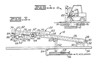
- FIGURE 1 is a view illustrating a lift truck having an accelerator pedal including directional control pedal portions;
- FIGURE 2 is a plan view illustrating an embodiment of the control pedal of the present invention; and
- FIGURE 3 is a side view illustrating the control pedal as seen from line III-III of Figure 2.
- Referring to Figure 1, a vehicle, for example a fork lift truck, is designated 10 and includes a generally well known vehicle control system including an accelerator control 12 operably connected in the system. Also, a well known vehicle forward
directional control 14 is operably connected in the system as is a well known vehicle reversedirectional control 16. - Generally, a
control pedal 18 is mounted on the vehicle and includesfirst means 20 on the pedal for actuating accelerator control 12. Asecond means 22 is mounted on the pedal for actuating the vehicle forwarddirectional control 14. Also, athird means 24 is mounted on the pedal for actuating the vehicle reversedirectional control 16. - The foregoing generally described the well known single pedal control concept for actuating acceleration, forward direction and reverse direction.
- In this invention,
control pedal 18, Figures 2, 3, includesaccelerator portion 20 as well asmeans Accelerator portion 20 comprises an underside surface 39 and is preferably of cast aluminum although other materials may be used.Portion 20 includesnubs 26 atend 27 thereof. Each of thenubs 26 includes abore 28 for accommodating a lubricated or bearing mountedpin 30 or the like for pivotally connectingportion 20 ofpedal 18 toflanges 32 onfloorboard 34 in the well known manner. - A waffle-like substantially
non-slip surface portion 36 is formedadjacent end 27 for accommodating the heel portion of the operator's foot.Surface 36 may be cast intoportion 20 or, alternatively, a rubber or synthetic insert may be applied toportion 20. - Extending from
heel portion 36 is aportion 38 for accommodating the ball portion of the operator's foot.Portion 38 may similarly include a cast-in substantially non-slip surface or, alternatively, may include a rubber or synthetic insert. -
Voids 40 are formed intoportion 20 ofpedal 18adjacent portion 38 for accommodating thedirectional control portions voids 40 include aflange 42 having a bore 44 formed therein.Opposite flange 42 is a nub or flange 46 formed on the underside ofportion 20 and having a bore 48 formed therein in axial alignment with bore 44. - A
flange 50 is also formed on the underside ofportion 20 providing for connection to the vehicle accelerator vialinks resilient means 58 in the well known manner. - Inasmuch as
members member 22, will be described in detail.Member 22 is also preferably of cast aluminum although it is recognized that other materials may be substituted.Member 22 is pivotally mounted on and movable relative toaccelerator portion 20.Member 22 is substantially elongated and has afirst end 60 and a second end 62. Between first andsecond ends 60, 62 is an enlargedportion 64 having abore 66 formed therethrough. Bore 66 accommodates a lubricated or bearing mounted pin 67 or the like inserted into bores 44, 48 for pivotally mountingmember 22 onaccelerator portion 20. Pin 67 is secured in place by setscrew 69. - A substantially non-slip surface 68 is provided adjacent
first end 60. Surface 68 is preferably a rubber or synthetic material insert applied tomember 22 and formed in the shape of an arrowhead indicating the directional response which it is connected to control. Alternatively,surface 68a ofmember 24 indicates a directional response opposite to that of surface 68. - A nub or
stop 70 is formed onmember 22 betweenend 60 andportion 64 for engagement withaccelerator portion 20 to limit upward movement ofmember 22 relative toportion 20. Similarly, another nub or stop 72 is formed onmember 22 between end 62 andportion 64 for engagement withaccelerator portion 20 to limit upward movement ofmember 22 relative toportion 20. - Resilient means such as steel spring 74 is preferably coiled around pin-67 and terminates at a first end 76 and a
second end 78. First end 76 is urged into engagement withaccelerator portion 20 andsecond end 78 is urged into engagement withmember 22. In this manner,member 22 is resiliently mounted onaccelerator portion 20 and biased so thatfirst end 60 protrudes aboveaccelerator portion 20 ofpedal 18 and second end 62 protrudes belowportion 20 ofpedal 18. In this "at rest" or deactuated position,nub 70 is urged into contact with a portion of the underside ofportion 20. - A switch control means 80 includes a pair of
switching devices accelerator portion 20 ofpedal 18. Such a switch is sold by MICRO SWITCH as a catalogue number 516SS series solid state switch. A switch is required for each direction to be controlled, i.e., forward and reverse. As used in this invention,switch 80F is mounted onportion 20 ofpedal 18 adjacent second end 62 ofmember 22. Also, switch 80R is similarly mountedadjacent member 24. Preferably, switches 80F, 80R are mounted in an epoxy-filledcontainer 82 formed of a synthetic or other suitable material.Wires switches Screws 88 are used to secureflanges 90 ofcontainer 82 toportion 20. In this manner, switch control means 80 is mounted on and movable withaccelerator portion 20 ofpedal 18. - A means for actuating switch control means 80, such as
magnet 92, is mounted on and movable with second end 62 ofmember 22.Magnet 92 is mounted on the second end of eachmember accelerator portion 20 and thus also movable relative to switch control means 80.Magnet 92 is secured on second end 62 by a retainer or clip 94, preferably of a synthetic material, which is mounted onmember 22 by ascrew 96, or the like. Anend 98 ofmagnet 92 is spaced fromswitch 80F so that, as it is well known, movement ofmagnet 92 into proximity withswitch 80F will actuate the switch and thus electrically control the direction of vehicle 10. The strength ofmagnet 92 needed to actuateswitch 80F is dependent upon the size ofmagnet 92 and the spacing betweenend 98 andswitch 80F whenmagnet 92 is moved to positionadjacent switch 80F. Such a position is achieved when nub 72 engages the underside ofaccelerator portion 20. However, themagnet 92 must not be of such strength to actuateswitch 80F whenmember 22 is in the "at rest" position whereinnub 70 engages the underside ofpedal portion 20. It was found, for purposes of this invention, that a cylindrical magnet having a diameter of about 9.53 mm (0.375 inches) and a length of about 31.75 mm (1.25 inches) was sufficient to actuateswitch 80F as desired when spaced fromend 98 at about 1.59 mm (.0625 inches). The shape ofmagnet 92 is not critical, although a cylindrical shape is convenient and is preferred. - A downwardly directed force applied to surface 68 of
member 22 adjacentfirst end 60causes member 22 to pivot about pin 67 relative toaccelerator portion 20 so thatmagnet 92 adjacent second end 62 moves upwardly until stop 72 abuts the underside ofaccelerator portion 20. As a result,magnet 92 is moved into positionadjacent switch 80F in switch control means 80, and thus switch 80F is actuated to signal the electrically operated transmission of vehicle 10 to direct vehicle 10 in a forward direction. Also, theentire pedal 18 includingaccelerator portion 20 and forwarddirectional portion 22 can be pivoted aboutpins 30 to accelerate vehicle 10 in a forward direction. - Release of the force applied to surface 68
permits member 22 to be pivotally urged by resilient member 74 so that nub 70 engagesaccelerator portion 20. In this position,first end 60 protrudes aboveaccelerator portion 20 and second end 62 protrudes belowaccelerator portion 20. - From the foregoing it can be seen that second end 62 moves in response to movement of
first end 60. Thus, first and second ends 60, 62, respectively, pivot simultaneously towardaccelerator portion 20. - Force applied to
member 24 results in similar action except that actuation ofswitch 80R results in directing vehicle 10 in a reverse direction. -
Switches actuator magnets 92 thus making extended wear life a possibility due to the absence of direct switch contact known in prior art control pedals. Further, mountingswitches accelerator portion 20 and mountingmagnets 92 on second end 62 ofmember 22 which is underaccelerator portion 20, offers protection from debris interference with switch actuation. - Other aspects, objects and advantages of this invention can be obtained from a study of the drawings, the disclosure and the appended claims.
Claims (10)
Applications Claiming Priority (2)
| Application Number | Priority Date | Filing Date | Title |
|---|---|---|---|
| US919886 | 1978-06-28 | ||
| US05/919,886 US4179949A (en) | 1978-06-28 | 1978-06-28 | Control pedal |
Publications (2)
| Publication Number | Publication Date |
|---|---|
| EP0006427A1 EP0006427A1 (en) | 1980-01-09 |
| EP0006427B1 true EP0006427B1 (en) | 1982-11-17 |
Family
ID=25442809
Family Applications (1)
| Application Number | Title | Priority Date | Filing Date |
|---|---|---|---|
| EP79101303A Expired EP0006427B1 (en) | 1978-06-28 | 1979-04-30 | Control pedal |
Country Status (4)
| Country | Link |
|---|---|
| US (1) | US4179949A (en) |
| EP (1) | EP0006427B1 (en) |
| CA (1) | CA1104471A (en) |
| DE (1) | DE2964043D1 (en) |
Families Citing this family (12)
| Publication number | Priority date | Publication date | Assignee | Title |
|---|---|---|---|---|
| US4455466A (en) * | 1982-04-21 | 1984-06-19 | Wilson Dallas W | Switch actuating mechanism |
| JPS5976424U (en) * | 1982-11-15 | 1984-05-24 | 三菱電機株式会社 | automatic starting device |
| US4558194A (en) * | 1984-03-21 | 1985-12-10 | Towmotor Corporation | Foot pedal switch |
| US5216935A (en) * | 1988-12-16 | 1993-06-08 | Kubota Ltd. | Bidirectional control arrangement for vehicle |
| FR2647064B1 (en) * | 1989-05-16 | 1991-09-27 | Peugeot | BRAKING DEVICE FOR A MOTOR VEHICLE EQUIPPED WITH AN ELECTRIC MOTOR |
| US5133225A (en) * | 1991-01-15 | 1992-07-28 | Williams Controls, Inc. | Electronic foot pedal having improved biasing arrangement |
| US5237891A (en) * | 1991-01-15 | 1993-08-24 | Williams Controls, Inc. | Electronic foot pedal having improved biasing arrangement |
| US5509496A (en) * | 1994-06-07 | 1996-04-23 | Murray, Inc. | Lawn and garden tractor hydrostatic foot control system |
| US6041673A (en) * | 1998-12-18 | 2000-03-28 | Caterpillar Inc. | Dual function throttle control system for heavy construction equipment machines |
| US6408712B1 (en) | 1999-10-15 | 2002-06-25 | Teleflex Incorporated, | Pedal assembly with non-contact pedal position sensor for generating a control signal |
| JP2004123334A (en) * | 2002-10-03 | 2004-04-22 | Toyota Industries Corp | Accelerator pedal for industrial vehicles |
| DE102014017973A1 (en) * | 2014-12-04 | 2016-06-09 | Wabco Gmbh | Brake pedal assembly of a steering-brakable vehicle, in particular a tractor |
Family Cites Families (9)
| Publication number | Priority date | Publication date | Assignee | Title |
|---|---|---|---|---|
| US2873407A (en) * | 1955-02-07 | 1959-02-10 | Thomas E Leonard | Pedal and switch structure for vehicles |
| FR1157008A (en) * | 1956-07-27 | 1958-05-23 | Alexandre Ets | Improvements made to apparatus and devices comprising an electrical contact operable by the foot, and in particular to such apparatus constituted as rheostats |
| DE1952345A1 (en) * | 1969-10-13 | 1971-05-06 | Werner Goering | Safety gas brake combination for motor vehicles |
| US3726369A (en) * | 1971-01-14 | 1973-04-10 | J Esteves | Automatic brake actuator |
| AU501032B2 (en) * | 1974-10-02 | 1979-06-07 | Y Nakanishi | One pin hinge |
| DE2511020A1 (en) * | 1975-03-11 | 1976-09-23 | Guenter Teetz | Accelerator and brake pedal mechanism for motor vehicles - has electromagnetic interlock system to speed brake application |
| US3995510A (en) * | 1975-05-05 | 1976-12-07 | Towmotor Corporation | Control system for a hydrostatic transmission |
| US4064769A (en) * | 1975-11-24 | 1977-12-27 | Caterpillar Tractor Co. | Control pedal-mechanical speed with electrical direction control |
| US4026164A (en) * | 1976-02-26 | 1977-05-31 | J. I. Case Company | Brake pedel assembly |
-
1978
- 1978-06-28 US US05/919,886 patent/US4179949A/en not_active Expired - Lifetime
-
1979
- 1979-04-26 CA CA326,395A patent/CA1104471A/en not_active Expired
- 1979-04-30 EP EP79101303A patent/EP0006427B1/en not_active Expired
- 1979-04-30 DE DE7979101303T patent/DE2964043D1/en not_active Expired
Also Published As
| Publication number | Publication date |
|---|---|
| US4179949A (en) | 1979-12-25 |
| CA1104471A (en) | 1981-07-07 |
| EP0006427A1 (en) | 1980-01-09 |
| DE2964043D1 (en) | 1982-12-23 |
Similar Documents
| Publication | Publication Date | Title |
|---|---|---|
| US4179949A (en) | Control pedal | |
| US20060185469A1 (en) | Pedal for motorized vehicle | |
| US4604506A (en) | Self-adjusting switch mechanism | |
| US4250768A (en) | Control pedal | |
| EP0990782A1 (en) | Accelerator pedal mechanism for vehicle | |
| JPH02292612A (en) | remote control lever module | |
| EP0267881B1 (en) | Duplex-type distributor for a pneumatic braking system for a motor vehicle equipped with an auxiliary slowing device | |
| US7168519B2 (en) | Switch mounting assembly | |
| CA2444122C (en) | Accelerator pedal for industrial vehicle | |
| US6241068B1 (en) | Shift lever assembly with a pre-load releasable interlock | |
| US6278070B1 (en) | Steering column switch with microswitches that has two operating positions and one neutral position system for cleaning windscreens | |
| US4439650A (en) | Switch assembly for automotive pedal construction | |
| US7823480B2 (en) | Support bracket with an integrated switch for a pedal assembly | |
| US5321219A (en) | Lever actuated pedal operated switch assembly | |
| US11173888B2 (en) | Parking brake actuation system for a vehicle | |
| JPH0795409B2 (en) | Control device for on / off operation switch | |
| US4938057A (en) | Parking brake device | |
| US3287520A (en) | Foot-actuated switch assembly | |
| US4128146A (en) | Remote control circuit for electric trailer brakes | |
| EP0021647B1 (en) | An operating mechanism for an hydraulic cylinder | |
| KR101116720B1 (en) | Support bracket with an integrated switch for a pedal assembly | |
| JPS61150834A (en) | Hand grip having action as deadman device for machine at site of construction | |
| US20260099166A1 (en) | Pedal device for a motor vehicle | |
| KR100204788B1 (en) | Position switch of automatic transmission | |
| JPS6037618Y2 (en) | Foot-operated gear shift operation device |
Legal Events
| Date | Code | Title | Description |
|---|---|---|---|
| PUAI | Public reference made under article 153(3) epc to a published international application that has entered the european phase |
Free format text: ORIGINAL CODE: 0009012 |
|
| 17P | Request for examination filed | ||
| AK | Designated contracting states |
Designated state(s): DE FR GB IT SE |
|
| ITF | It: translation for a ep patent filed | ||
| GRAA | (expected) grant |
Free format text: ORIGINAL CODE: 0009210 |
|
| AK | Designated contracting states |
Designated state(s): DE FR GB IT SE |
|
| REF | Corresponds to: |
Ref document number: 2964043 Country of ref document: DE Date of ref document: 19821223 |
|
| PLBI | Opposition filed |
Free format text: ORIGINAL CODE: 0009260 |
|
| 26 | Opposition filed |
Opponent name: LINDE AKTIENGESELLSCHAFT, WIESBADEN Effective date: 19830726 |
|
| PLBN | Opposition rejected |
Free format text: ORIGINAL CODE: 0009273 |
|
| STAA | Information on the status of an ep patent application or granted ep patent |
Free format text: STATUS: OPPOSITION REJECTED |
|
| 27O | Opposition rejected |
Effective date: 19840922 |
|
| ITPR | It: changes in ownership of a european patent |
Owner name: CAMBIO RAGIONE SOCIALE;CATERPILLAR INDUSTRIAL INC. |
|
| REG | Reference to a national code |
Ref country code: FR Ref legal event code: CD |
|
| PGFP | Annual fee paid to national office [announced via postgrant information from national office to epo] |
Ref country code: DE Payment date: 19890410 Year of fee payment: 11 |
|
| PGFP | Annual fee paid to national office [announced via postgrant information from national office to epo] |
Ref country code: SE Payment date: 19890502 Year of fee payment: 11 |
|
| PGFP | Annual fee paid to national office [announced via postgrant information from national office to epo] |
Ref country code: FR Payment date: 19900309 Year of fee payment: 12 |
|
| PGFP | Annual fee paid to national office [announced via postgrant information from national office to epo] |
Ref country code: GB Payment date: 19900331 Year of fee payment: 12 |
|
| ITTA | It: last paid annual fee | ||
| PG25 | Lapsed in a contracting state [announced via postgrant information from national office to epo] |
Ref country code: SE Effective date: 19900501 |
|
| PG25 | Lapsed in a contracting state [announced via postgrant information from national office to epo] |
Ref country code: FR Effective date: 19901228 |
|
| PG25 | Lapsed in a contracting state [announced via postgrant information from national office to epo] |
Ref country code: DE Effective date: 19910101 |
|
| REG | Reference to a national code |
Ref country code: FR Ref legal event code: ST |
|
| PG25 | Lapsed in a contracting state [announced via postgrant information from national office to epo] |
Ref country code: GB Effective date: 19910430 |
|
| GBPC | Gb: european patent ceased through non-payment of renewal fee | ||
| EUG | Se: european patent has lapsed |
Ref document number: 79101303.0 Effective date: 19910114 |