EP0006116A1 - Engine mounting base - Google Patents
Engine mounting base Download PDFInfo
- Publication number
- EP0006116A1 EP0006116A1 EP79101305A EP79101305A EP0006116A1 EP 0006116 A1 EP0006116 A1 EP 0006116A1 EP 79101305 A EP79101305 A EP 79101305A EP 79101305 A EP79101305 A EP 79101305A EP 0006116 A1 EP0006116 A1 EP 0006116A1
- Authority
- EP
- European Patent Office
- Prior art keywords
- mounting base
- fluid
- engine mounting
- hollow frame
- tube
- Prior art date
- Legal status (The legal status is an assumption and is not a legal conclusion. Google has not performed a legal analysis and makes no representation as to the accuracy of the status listed.)
- Granted
Links
- 239000012530 fluid Substances 0.000 claims abstract description 62
- 239000010687 lubricating oil Substances 0.000 claims description 6
- 238000009434 installation Methods 0.000 description 5
- 238000004891 communication Methods 0.000 description 3
- 238000010276 construction Methods 0.000 description 2
- 230000005484 gravity Effects 0.000 description 2
- 230000001050 lubricating effect Effects 0.000 description 2
- 229910000831 Steel Inorganic materials 0.000 description 1
- 230000009977 dual effect Effects 0.000 description 1
- 239000002184 metal Substances 0.000 description 1
- 238000005086 pumping Methods 0.000 description 1
- 239000010959 steel Substances 0.000 description 1
Images

Classifications
-
- F—MECHANICAL ENGINEERING; LIGHTING; HEATING; WEAPONS; BLASTING
- F01—MACHINES OR ENGINES IN GENERAL; ENGINE PLANTS IN GENERAL; STEAM ENGINES
- F01D—NON-POSITIVE DISPLACEMENT MACHINES OR ENGINES, e.g. STEAM TURBINES
- F01D25/00—Component parts, details, or accessories, not provided for in, or of interest apart from, other groups
- F01D25/28—Supporting or mounting arrangements, e.g. for turbine casing
-
- F—MECHANICAL ENGINEERING; LIGHTING; HEATING; WEAPONS; BLASTING
- F02—COMBUSTION ENGINES; HOT-GAS OR COMBUSTION-PRODUCT ENGINE PLANTS
- F02B—INTERNAL-COMBUSTION PISTON ENGINES; COMBUSTION ENGINES IN GENERAL
- F02B63/00—Adaptations of engines for driving pumps, hand-held tools or electric generators; Portable combinations of engines with engine-driven devices
- F02B63/04—Adaptations of engines for driving pumps, hand-held tools or electric generators; Portable combinations of engines with engine-driven devices for electric generators
-
- F—MECHANICAL ENGINEERING; LIGHTING; HEATING; WEAPONS; BLASTING
- F16—ENGINEERING ELEMENTS AND UNITS; GENERAL MEASURES FOR PRODUCING AND MAINTAINING EFFECTIVE FUNCTIONING OF MACHINES OR INSTALLATIONS; THERMAL INSULATION IN GENERAL
- F16M—FRAMES, CASINGS OR BEDS OF ENGINES, MACHINES OR APPARATUS, NOT SPECIFIC TO ENGINES, MACHINES OR APPARATUS PROVIDED FOR ELSEWHERE; STANDS; SUPPORTS
- F16M1/00—Frames or casings of engines, machines or apparatus; Frames serving as machinery beds
- F16M1/04—Frames or casings of engines, machines or apparatus; Frames serving as machinery beds for rotary engines or similar machines
-
- F—MECHANICAL ENGINEERING; LIGHTING; HEATING; WEAPONS; BLASTING
- F16—ENGINEERING ELEMENTS AND UNITS; GENERAL MEASURES FOR PRODUCING AND MAINTAINING EFFECTIVE FUNCTIONING OF MACHINES OR INSTALLATIONS; THERMAL INSULATION IN GENERAL
- F16M—FRAMES, CASINGS OR BEDS OF ENGINES, MACHINES OR APPARATUS, NOT SPECIFIC TO ENGINES, MACHINES OR APPARATUS PROVIDED FOR ELSEWHERE; STANDS; SUPPORTS
- F16M5/00—Engine beds, i.e. means for supporting engines or machines on foundations
-
- F—MECHANICAL ENGINEERING; LIGHTING; HEATING; WEAPONS; BLASTING
- F16—ENGINEERING ELEMENTS AND UNITS; GENERAL MEASURES FOR PRODUCING AND MAINTAINING EFFECTIVE FUNCTIONING OF MACHINES OR INSTALLATIONS; THERMAL INSULATION IN GENERAL
- F16N—LUBRICATING
- F16N1/00—Constructional modifications of parts of machines or apparatus for the purpose of lubrication
-
- F—MECHANICAL ENGINEERING; LIGHTING; HEATING; WEAPONS; BLASTING
- F02—COMBUSTION ENGINES; HOT-GAS OR COMBUSTION-PRODUCT ENGINE PLANTS
- F02B—INTERNAL-COMBUSTION PISTON ENGINES; COMBUSTION ENGINES IN GENERAL
- F02B63/00—Adaptations of engines for driving pumps, hand-held tools or electric generators; Portable combinations of engines with engine-driven devices
- F02B63/04—Adaptations of engines for driving pumps, hand-held tools or electric generators; Portable combinations of engines with engine-driven devices for electric generators
- F02B63/044—Adaptations of engines for driving pumps, hand-held tools or electric generators; Portable combinations of engines with engine-driven devices for electric generators the engine-generator unit being placed on a frame or in an housing
- F02B2063/045—Frames for generator-engine sets
-
- F—MECHANICAL ENGINEERING; LIGHTING; HEATING; WEAPONS; BLASTING
- F02—COMBUSTION ENGINES; HOT-GAS OR COMBUSTION-PRODUCT ENGINE PLANTS
- F02B—INTERNAL-COMBUSTION PISTON ENGINES; COMBUSTION ENGINES IN GENERAL
- F02B63/00—Adaptations of engines for driving pumps, hand-held tools or electric generators; Portable combinations of engines with engine-driven devices
- F02B63/04—Adaptations of engines for driving pumps, hand-held tools or electric generators; Portable combinations of engines with engine-driven devices for electric generators
- F02B63/044—Adaptations of engines for driving pumps, hand-held tools or electric generators; Portable combinations of engines with engine-driven devices for electric generators the engine-generator unit being placed on a frame or in an housing
Definitions
- the present invention it related to an engine mounting base and a portion of a fluid distribution system for the engine utilizing the mounting base.
- Integrated enclosures and rigid mounting arrangements for engines which allow convenient transport thereof as a self-contained power plant package.
- the rigid base therefore eliminates the need for attachment of the engine to an auxiliary mounting base prepared for it at the installation site and generally greatly simplifies the installation procedure.
- U.S. Patent No. 3,418,485 issued December 24, 1968 to H. R. Anderson et al assigned to the assignee of the instant application, showing an enclosure for a gas turbine engine and associated electric generator set. That reference discloses a rigid base that not only supports the engine, but also defines a sump or reservoir for the lubricating oil of the engine.
- Self-contained power plant packages of the aforementioned type are therefore very desirable for roof-top installation, emergency use in the field, and the like.
- the present invention is directed to overcoming one or more of the problems as set forth above.
- an engine mounting base having a first hollow frame portion containing a fluid at generally atmospheric pressure, and a second hollow frame portion containing fluid at a preselected pressure level above atmospheric pressure, and with the frame portions being connected together.
- the hollow frame portions of the instant engine mounting base are made from structural strength tubing having closed ends.
- the tubes are preferably connected together, interconnected in a preselected manner to provide common chambers, and arranged at different elevations so as to provide an effective portion of a fluid distribution system as well as a simple and yet rigid engine mounting base.
- Fig. 1 is a diagrammatic, perspective view of an engine mounting base constructed in accordance with one embodiment of the present invention, with portions broken open to better illustrate details thereof, and showing a fragmentary portion of an associated engine elevated above its mounted position on the mounting base for clarity.
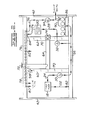
- Fig. 2 is a diagrammatic, plan view of the engine mounting base illustrated in Fig. 1 showing the various fluid chambers and fluid flow paths providing a portion of an engine fluid distribution system.
- an engine mounting base or engine support apparatus 8 for supporting a plurality of support feet 10 of a dual shaft gas turbine engine 12.
- the gas turbine engine has a gasifier turbine portion 14 and a power turbine portion 16 which operate at different rotational speeds, and these separate portions respectively drive first and second engine driven pumps 18 and 20 as is known in the art.
- first pump has fluid inlet and outlet passages 22,24 and the second pump has corresponding fluid inlet and outlet passages 26,28, first and second one-way check valves 30,32 are provided individually on the respective outlet passages 24,28 for purposes which will be later explained.
- the engine mounting base 8 includes a first hollow frame means or reservoir portion 34, a second hollow frame means or high pressure portion 36, a third hollow frame means or fluid collecting portion 38, and a fourth hollow frame means or intermediate pressure portion 40.
- a pair of substantially parallel, tube-closing end plates 42 provide additional strength for the mounting base, and a lifting eye 44 is defined at each end of the plates for lifting or skidding the mounting base 8 and engine 12 as a self-contained unit during initial installation thereof.
- the reservoir portion 34 of the instant example includes a substantially parallel pair of longitudinally oriented elongate tubes 46,48, and a pair of substantially parallel elongate cross tubes 50, 52 extending transversely between the tubes 46,48.
- These tubes and the closing end plates 42 define a common reservoir chamber 54 containing a preselected quantity of fluid such as lubricating oil at generally atmospheric pressure.
- the high pressure portion 36 includes a longitudinally oriented elongate tube 56 having opposite ends closed off by the end plates 42 and defining a high pressure chamber 58 therein.
- the tubes 46,56 are preferably substantially rectangular in cross section as shown by the broken open portion in Fig. 1. This permits the tubes to be elevationally stacked on top of one another for increased beam depth and strength. Specifically, for example, the tube 56 is disposed on top of the tube 46.
- the fluid collecting portion 38 includes a substantially parallel pair of elongate cross tubes 60,62 and a longitudinally oriented tube 64 connected therebetween and defining a generally H-shaped collecting chamber 66.
- the ends of the cross tubes 60,62 are closed or blocked, except for an opening 68.
- a plurality of flow-restricting openings 70 of preselected cross sectional area are defined between the collecting chamber 66 and the reservoir chamber 54, both at the juxtaposed surfaces of the elevationally aligned cross tubes 50,60 as representatively illustrated, and also at the cross tubes 52,62.
- a breather pipe 72 extends upwardly from the top of the tube 64 and to the side of the mounting base 8 where it is subsequently connected to an upright vent pipe, not shown, at the installation site.
- a main fluid return or drain opening 74 is also provided through the top of the cross tube 62, and this drain opening communicates with the bottom of the gas turbine engine 12.
- the intermediate pressure portion 40 includes a longitudinally oriented elongate tube 76 located immediately above the tube 48, and connected thereto and to the cross tubes 60,62. Since the ends of the tube 76 are blocked by the end plates 42, a chamber 77 is defined therein that could serve as an intermediate pressure manifold. However, because the chamber 77 is difficult to clean during initial assembly of the mounting base 8, an intermediate pressure distribution manifold 78 is connected inside the tube 76 for this purpose. A plurality of conduits 80 are connected to the manifold 78 and extend outwardly of the tube 76 to distribute fluid as needed to the gas turbine engine 12.
- a fluid filter assembly 86 is connected to the inside faces of the tubes 46,56 and is in fluid communication with the high pressure chamber 58 as by one or more passages 88.
- An outlet conduit or passage 90 from the filter assembly is in fluid communication with a branch conduit 92 leading to the engine 12.
- a conventional relief valve 94 set for example at about 300 psi (2,070 KPa), is in series relation with the conduit 90 so that relatively high pressure fluid at such pressure is present in the chamber 58 and in the branch conduit 92. Fluid relieved past the relief valve communicates through a conduit 96 to the distribution manifold 78 located within the tube 76.
- Another conventional relief valve 98 extends through the opening 68 and is in communication with fluid within the manifold 78.
- This second relief valve 98 establishes the pressure in the manifold and the plurality of conduits 80 leading therefrom and to the engine 12. Fluid relieved past the second relief valve is communicated to the cross tube 60 and to the fluid collecting portion 38.
- the first and second pumps are driven at different rates of speed corresponding to the rotational speeds of the gasifier turbine portion 14 and power turbine portion 16, respectively. Consequently, the check valves 30,32 are provided in the outlet or discharge passages 24,28 thereof to prevent either pump having to start up under a higher fluid back pressure established by the other pump.
- the reservoir chamber 54 of the mounting base 8 is substantially completely filled with lubricating fluid at generally atmospheric pressure, and the pumps 18,20 have approximately the same fluid pumping capacities to enable fluid to be drawn from the opposite sides of the reservoir portion 34 at about the same rate as is illustrated in both Figs. 1 and 2. Thence, the fluid is delivered to the high pressure chamber 58 so that it is also substantially completely filled. The fluid is subsequently filtered by the filter assembly 86 and delivered to the branch conduit 92 to the gas-turbine engine 12. Accordingly, high pressure fluid is available thereat for a multiplicity of operating purposes. Fluid not needed by the engine via the conduit 92 is directed through the relief valve 94 to the conduit 96 and to the distribution manifold 78 as shown by the flow indicating arrows on the drawings. Therefore, fluid under an intermediate pressure is available thereat for various operating needs, and a plurality of conduits 80 serve to communicate such fluid to parts of the gas turbine engine 12 as necessary.
- Fluid not needed by the distribution manifold 78 is directed through the second relief valve 98 into the collecting portion 38 at a preselected flow rate. Specifically, such rate is about the same flow rate as that returning from the gas turbine engine 12 via the main drain opening 74.
- equivalent amounts of fluid are returned to the collecting portion at the opposite cross tubes 60,62, with the plurality of sized openings 70 serving to uniformly distribute the gravity flow of fluid from the upper collecting portion to the lower reservoir portion 34.
- the subject mounting base 8 is economical and strong in its construction, such as by consisting primarily of a plurality of close-ended tubes welded or otherwise connected together, for example, structural strength tubes of steel.
- the tubes are interconnected at various elevations to provide several fluid chambers containing preselected quantities of fluid and individually established at atmospheric pressure and at different pressure levels above atmospheric pressure, so that a portion of an engine fluid distribution system is provided by the mounting base in addition to supporting the engine.
- the pumps 18,20 draw fluid from the lower level reservoir portion 34 and deliver the fluid to the upper level high pressure and intermediate pressure portions 36,40, with the return of fluid from the engine 12 being accommodated by gravity flow through the upper collecting portion 38 back to the reservoir portion.
Landscapes
- Engineering & Computer Science (AREA)
- General Engineering & Computer Science (AREA)
- Mechanical Engineering (AREA)
- Chemical & Material Sciences (AREA)
- Combustion & Propulsion (AREA)
- Lubrication Details And Ventilation Of Internal Combustion Engines (AREA)
Abstract
Description
- The present invention it related to an engine mounting base and a portion of a fluid distribution system for the engine utilizing the mounting base.
- Integrated enclosures and rigid mounting arrangements for engines are known which allow convenient transport thereof as a self-contained power plant package. The rigid base therefore eliminates the need for attachment of the engine to an auxiliary mounting base prepared for it at the installation site and generally greatly simplifies the installation procedure. For example, reference is made to U.S. Patent No. 3,418,485 issued December 24, 1968 to H. R. Anderson et al, assigned to the assignee of the instant application, showing an enclosure for a gas turbine engine and associated electric generator set. That reference discloses a rigid base that not only supports the engine, but also defines a sump or reservoir for the lubricating oil of the engine. Self-contained power plant packages of the aforementioned type are therefore very desirable for roof-top installation, emergency use in the field, and the like.
- Heretofore, relatively complex and fabricated sheet metal reservoirs have been utilized on these self-contained power plants. Moreover, separate fluid control systems have been incorporated on the engine to permit a sufficient quantity of lubricating fluid to be delivered to the engine bearings and to other components at the desired pressure. While such systems have performed adequately, they have been relatively costly in construction and have not been as effective as desired.
- The present invention is directed to overcoming one or more of the problems as set forth above.
- In accordance with one aspect of the present invention, an engine mounting base is provided having a first hollow frame portion containing a fluid at generally atmospheric pressure, and a second hollow frame portion containing fluid at a preselected pressure level above atmospheric pressure, and with the frame portions being connected together.
- In another aspect of the invention, the hollow frame portions of the instant engine mounting base are made from structural strength tubing having closed ends. The tubes are preferably connected together, interconnected in a preselected manner to provide common chambers, and arranged at different elevations so as to provide an effective portion of a fluid distribution system as well as a simple and yet rigid engine mounting base.
- Fig. 1 is a diagrammatic, perspective view of an engine mounting base constructed in accordance with one embodiment of the present invention, with portions broken open to better illustrate details thereof, and showing a fragmentary portion of an associated engine elevated above its mounted position on the mounting base for clarity.
- Fig. 2 is a diagrammatic, plan view of the engine mounting base illustrated in Fig. 1 showing the various fluid chambers and fluid flow paths providing a portion of an engine fluid distribution system.
- Referring to Fig. 1, one embodiment of an engine mounting base or engine support apparatus 8 is shown for supporting a plurality of
support feet 10 of a dual shaftgas turbine engine 12. Hence, the gas turbine engine has a gasifier turbine portion 14 and a power turbine portion 16 which operate at different rotational speeds, and these separate portions respectively drive first and second engine drivenpumps outlet passages outlet passages way check valves respective outlet passages - Basically, however, the engine mounting base 8 includes a first hollow frame means or
reservoir portion 34, a second hollow frame means orhigh pressure portion 36, a third hollow frame means or fluid collecting portion 38, and a fourth hollow frame means or intermediate pressure portion 40. A pair of substantially parallel, tube-closing end plates 42 provide additional strength for the mounting base, and a liftingeye 44 is defined at each end of the plates for lifting or skidding the mounting base 8 andengine 12 as a self-contained unit during initial installation thereof. - More particularly, the
reservoir portion 34 of the instant example includes a substantially parallel pair of longitudinally orientedelongate tubes elongate cross tubes tubes closing end plates 42 define acommon reservoir chamber 54 containing a preselected quantity of fluid such as lubricating oil at generally atmospheric pressure. - The
high pressure portion 36 includes a longitudinally orientedelongate tube 56 having opposite ends closed off by theend plates 42 and defining ahigh pressure chamber 58 therein. Thetubes tube 56 is disposed on top of thetube 46. - In a similar manner, the fluid collecting portion 38 includes a substantially parallel pair of
elongate cross tubes shaped collecting chamber 66. The ends of thecross tubes opening 68. Moreover, a plurality of flow-restrictingopenings 70 of preselected cross sectional area are defined between thecollecting chamber 66 and thereservoir chamber 54, both at the juxtaposed surfaces of the elevationally alignedcross tubes cross tubes breather pipe 72 extends upwardly from the top of the tube 64 and to the side of the mounting base 8 where it is subsequently connected to an upright vent pipe, not shown, at the installation site. A main fluid return ordrain opening 74 is also provided through the top of thecross tube 62, and this drain opening communicates with the bottom of thegas turbine engine 12. - In the embodiment illustrated, the intermediate pressure portion 40 includes a longitudinally oriented elongate tube 76 located immediately above the
tube 48, and connected thereto and to thecross tubes end plates 42, achamber 77 is defined therein that could serve as an intermediate pressure manifold. However, because thechamber 77 is difficult to clean during initial assembly of the mounting base 8, an intermediatepressure distribution manifold 78 is connected inside the tube 76 for this purpose. A plurality ofconduits 80 are connected to themanifold 78 and extend outwardly of the tube 76 to distribute fluid as needed to thegas turbine engine 12. - It is of note to observe from Fig. 1 that the
inlet passage 22 of thefirst pump 18 is connected to thetube 46 as at anopening 82, and that theinlet passage 26 of thesecond pump 20 is connected to thetube 48 as at anopening 84 at the opposite sides of thereservoir portion 34. This assures more uniform withdrawal of fluid from the opposite extremities of the reservoir portion and improves reliability should the mounting base 8 be tipped in use. - A
fluid filter assembly 86 is connected to the inside faces of thetubes high pressure chamber 58 as by one ormore passages 88. An outlet conduit or passage 90 from the filter assembly is in fluid communication with abranch conduit 92 leading to theengine 12. Aconventional relief valve 94, set for example at about 300 psi (2,070 KPa), is in series relation with the conduit 90 so that relatively high pressure fluid at such pressure is present in thechamber 58 and in thebranch conduit 92. Fluid relieved past the relief valve communicates through aconduit 96 to thedistribution manifold 78 located within the tube 76. Anotherconventional relief valve 98 extends through theopening 68 and is in communication with fluid within themanifold 78. Thissecond relief valve 98, set for example at about 75 psi (520 KPa), establishes the pressure in the manifold and the plurality ofconduits 80 leading therefrom and to theengine 12. Fluid relieved past the second relief valve is communicated to thecross tube 60 and to the fluid collecting portion 38. - In operation, as the
gas turbine engine 12 is started, the first and second pumps are driven at different rates of speed corresponding to the rotational speeds of the gasifier turbine portion 14 and power turbine portion 16, respectively. Consequently, thecheck valves discharge passages - Under normal operating circumstances, the
reservoir chamber 54 of the mounting base 8 is substantially completely filled with lubricating fluid at generally atmospheric pressure, and thepumps reservoir portion 34 at about the same rate as is illustrated in both Figs. 1 and 2. Thence, the fluid is delivered to thehigh pressure chamber 58 so that it is also substantially completely filled. The fluid is subsequently filtered by thefilter assembly 86 and delivered to thebranch conduit 92 to the gas-turbine engine 12. Accordingly, high pressure fluid is available thereat for a multiplicity of operating purposes. Fluid not needed by the engine via theconduit 92 is directed through therelief valve 94 to theconduit 96 and to thedistribution manifold 78 as shown by the flow indicating arrows on the drawings. Therefore, fluid under an intermediate pressure is available thereat for various operating needs, and a plurality ofconduits 80 serve to communicate such fluid to parts of thegas turbine engine 12 as necessary. - Fluid not needed by the
distribution manifold 78 is directed through thesecond relief valve 98 into the collecting portion 38 at a preselected flow rate. Specifically, such rate is about the same flow rate as that returning from thegas turbine engine 12 via the main drain opening 74. Significantly then, equivalent amounts of fluid are returned to the collecting portion at theopposite cross tubes openings 70 serving to uniformly distribute the gravity flow of fluid from the upper collecting portion to thelower reservoir portion 34. These flow distributing features of the mounting base 8 are particularly useful, for example, when the self-contained package is tipped in use such as is typically the case in a marine gear application. This is also why thebreather pipe 72 is connected to the reservoir portion substantially centrally of the mounting base. - Thus it is apparent that the subject mounting base 8 is economical and strong in its construction, such as by consisting primarily of a plurality of close-ended tubes welded or otherwise connected together, for example, structural strength tubes of steel. Advantageously, the tubes are interconnected at various elevations to provide several fluid chambers containing preselected quantities of fluid and individually established at atmospheric pressure and at different pressure levels above atmospheric pressure, so that a portion of an engine fluid distribution system is provided by the mounting base in addition to supporting the engine. The
pumps level reservoir portion 34 and deliver the fluid to the upper level high pressure andintermediate pressure portions 36,40, with the return of fluid from theengine 12 being accommodated by gravity flow through the upper collecting portion 38 back to the reservoir portion. - Other aspects, objects, and advantages of this invention can be obtained from a study of the drawings, the disclosure, and the appended claims.
Claims (20)
Applications Claiming Priority (2)
| Application Number | Priority Date | Filing Date | Title |
|---|---|---|---|
| US913931 | 1978-06-08 | ||
| US05/913,931 US4191356A (en) | 1978-06-08 | 1978-06-08 | Engine mounting base |
Publications (2)
| Publication Number | Publication Date |
|---|---|
| EP0006116A1 true EP0006116A1 (en) | 1980-01-09 |
| EP0006116B1 EP0006116B1 (en) | 1982-12-01 |
Family
ID=25433741
Family Applications (1)
| Application Number | Title | Priority Date | Filing Date |
|---|---|---|---|
| EP79101305A Expired EP0006116B1 (en) | 1978-06-08 | 1979-04-30 | Engine mounting base |
Country Status (4)
| Country | Link |
|---|---|
| US (1) | US4191356A (en) |
| EP (1) | EP0006116B1 (en) |
| JP (1) | JPS54162013A (en) |
| CA (1) | CA1101818A (en) |
Cited By (4)
| Publication number | Priority date | Publication date | Assignee | Title |
|---|---|---|---|---|
| FR2519576A1 (en) * | 1982-01-11 | 1983-07-18 | Kroczynski Patrice | ROBOT WITH CLIPPERS |
| WO2010089010A1 (en) * | 2009-02-04 | 2010-08-12 | Sew-Eurodrive Gmbh & Co. Kg | Support element having a drive unit |
| DE102013019042A1 (en) * | 2013-11-15 | 2015-05-21 | Heye International Gmbh | Arrangement for supplying lubricant to a glass forming machine |
| IT201700060596A1 (en) * | 2017-06-01 | 2018-12-01 | Nuovo Pignone Tecnologie Srl | PLANT MODULE WITH PERFORATED BEAMS / PLANT MODULE WITH PERFORATED BEAMS |
Families Citing this family (27)
| Publication number | Priority date | Publication date | Assignee | Title |
|---|---|---|---|---|
| DE2914251A1 (en) * | 1979-04-09 | 1980-10-23 | Bbc Brown Boveri & Cie | FOUNDATION FOR A VIBRATION GENERATING MACHINE |
| USD279283S (en) | 1982-05-03 | 1985-06-18 | John Tate | Power supply support frame |
| JPS59203158A (en) * | 1983-05-06 | 1984-11-17 | フジタ工業株式会社 | Pc floor unit for machine factory |
| US4660799A (en) * | 1986-01-29 | 1987-04-28 | Butland Edward H | Load support structure |
| US4735310A (en) * | 1987-01-15 | 1988-04-05 | Teledyne Industries, Inc. | Aircraft engine shipping container with adjustable bracket supports |
| SE466967B (en) * | 1987-02-09 | 1992-05-04 | Volvo Penta Ab | BAEDD MOVES ENGINES WITH ADDITIONAL DEVICE |
| US4971286A (en) * | 1989-09-08 | 1990-11-20 | Silhan Mark A | Supportive framework |
| JPH0427296U (en) * | 1990-06-28 | 1992-03-04 | ||
| US5542642A (en) * | 1995-02-24 | 1996-08-06 | Tuthill Corporation | Turbine support structure |
| DE19755981B4 (en) * | 1997-12-17 | 2005-09-15 | Alstom | steam turbine plant |
| US6095482A (en) * | 1998-09-14 | 2000-08-01 | Lucent Technologies, Inc. | Universal equipment mounting structure and method of using |
| JP2000108813A (en) * | 1998-10-02 | 2000-04-18 | Honda Motor Co Ltd | Vehicle front structure |
| JP3842035B2 (en) * | 2000-11-10 | 2006-11-08 | 本田技研工業株式会社 | Oil-cooled engine device |
| US6520124B2 (en) | 2000-12-13 | 2003-02-18 | Tramont Corporation | Double walled fuel tank with integral generator set mounting frame |
| US7482705B2 (en) * | 2003-05-12 | 2009-01-27 | Piercey Iii Gerald S | Generator support plenum |
| US20080129053A1 (en) * | 2004-05-12 | 2008-06-05 | Piercey Gerald S | Engine-generator set |
| CA2577679A1 (en) * | 2004-08-18 | 2006-03-02 | Dms Electric Apparatus Services, Inc. | Transition base |
| USD537630S1 (en) * | 2004-12-22 | 2007-03-06 | Trimcast Pty Ltd | Container and frame for storage of propeller |
| US8230973B2 (en) * | 2007-11-29 | 2012-07-31 | GM Global Technology Operations LLC | Transmission pump system |
| US20090308876A1 (en) * | 2008-06-13 | 2009-12-17 | Christofferson Jeffry J | Aboveground Rectangular Secondary Containment Generator Base Tank with Internal Flexible Bladder |
| US7946554B2 (en) * | 2008-12-30 | 2011-05-24 | General Electric Company | Self-aligning support assembly and method for rotatable cylindrical components |
| US8534638B2 (en) * | 2010-05-06 | 2013-09-17 | Hamilton Sundstrand Corporation | Removable gas turbine engine stand |
| US20150114004A1 (en) * | 2013-10-31 | 2015-04-30 | General Electric Company | Gas turbine enclosure |
| US9777882B2 (en) * | 2015-12-03 | 2017-10-03 | Ingersoll-Rand Company | Skeleton base for a compressor system |
| IT202100003647A1 (en) * | 2021-02-17 | 2022-08-17 | Nuovo Pignone Tecnologie Srl | FLOODING CONTAINMENT TANK |
| US11814807B1 (en) | 2022-10-13 | 2023-11-14 | Great Plains Tower Products Llc | Ballast tray assembly for a tower structure |
| US12421685B2 (en) | 2022-08-10 | 2025-09-23 | Great Plains Tower Products Llc | Tower structure ballast tray interface |
Citations (5)
| Publication number | Priority date | Publication date | Assignee | Title |
|---|---|---|---|---|
| US1716132A (en) * | 1926-10-30 | 1929-06-04 | Westinghouse Electric & Mfg Co | Turbine-generator support |
| FR873662A (en) * | 1940-07-06 | 1942-07-16 | Maschf Augsburg Nuernberg Ag | Improvements made to internal combustion engines to improve the circulation of lubricating oil |
| DE851573C (en) * | 1951-04-12 | 1952-10-06 | Heinrich Popp | Machine base frame |
| US3330514A (en) * | 1965-08-03 | 1967-07-11 | Worthington Corp | Support structure for rotating machinery |
| DE2653154A1 (en) * | 1976-11-16 | 1978-05-18 | Sulzer Ag | FOUNDATION FRAME FOR MACHINE SETS CONSISTING OF COMBUSTION MACHINE AND GENERATOR |
Family Cites Families (9)
| Publication number | Priority date | Publication date | Assignee | Title |
|---|---|---|---|---|
| US975167A (en) * | 1910-02-14 | 1910-11-08 | Albert B Shultz | Engine-base. |
| US2632529A (en) * | 1945-06-20 | 1953-03-24 | Joseph E Kennedy | Tube mill and means for lubrication |
| US2568783A (en) * | 1948-03-04 | 1951-09-25 | Bauer Bros Co | Temperature controlled mill base |
| US2609891A (en) * | 1948-04-30 | 1952-09-09 | United Shoe Machinery Corp | Lubricating apparatus |
| US2963032A (en) * | 1953-11-06 | 1960-12-06 | Allis Chalmers Mfg Co | Hydraulic system for steam turbine |
| US3418485A (en) * | 1965-09-13 | 1968-12-24 | Caterpillar Tractor Co | Enclosure for gas turbine engine electric generator set |
| US3485324A (en) * | 1967-11-07 | 1969-12-23 | Allis Chalmers Mfg Co | Piston cooling system |
| US3623573A (en) * | 1970-02-19 | 1971-11-30 | Westinghouse Electric Corp | Lubrication system |
| US3910381A (en) * | 1974-05-28 | 1975-10-07 | Westinghouse Electric Corp | Lubricating oil system integral with structural steel turbine foundation |
-
1978
- 1978-06-08 US US05/913,931 patent/US4191356A/en not_active Expired - Lifetime
-
1979
- 1979-03-29 CA CA324,443A patent/CA1101818A/en not_active Expired
- 1979-04-30 EP EP79101305A patent/EP0006116B1/en not_active Expired
- 1979-05-15 JP JP5872379A patent/JPS54162013A/en active Granted
Patent Citations (5)
| Publication number | Priority date | Publication date | Assignee | Title |
|---|---|---|---|---|
| US1716132A (en) * | 1926-10-30 | 1929-06-04 | Westinghouse Electric & Mfg Co | Turbine-generator support |
| FR873662A (en) * | 1940-07-06 | 1942-07-16 | Maschf Augsburg Nuernberg Ag | Improvements made to internal combustion engines to improve the circulation of lubricating oil |
| DE851573C (en) * | 1951-04-12 | 1952-10-06 | Heinrich Popp | Machine base frame |
| US3330514A (en) * | 1965-08-03 | 1967-07-11 | Worthington Corp | Support structure for rotating machinery |
| DE2653154A1 (en) * | 1976-11-16 | 1978-05-18 | Sulzer Ag | FOUNDATION FRAME FOR MACHINE SETS CONSISTING OF COMBUSTION MACHINE AND GENERATOR |
Cited By (6)
| Publication number | Priority date | Publication date | Assignee | Title |
|---|---|---|---|---|
| FR2519576A1 (en) * | 1982-01-11 | 1983-07-18 | Kroczynski Patrice | ROBOT WITH CLIPPERS |
| WO2010089010A1 (en) * | 2009-02-04 | 2010-08-12 | Sew-Eurodrive Gmbh & Co. Kg | Support element having a drive unit |
| DE102013019042A1 (en) * | 2013-11-15 | 2015-05-21 | Heye International Gmbh | Arrangement for supplying lubricant to a glass forming machine |
| DE102013019042B4 (en) * | 2013-11-15 | 2016-10-27 | Heye International Gmbh | Arrangement for supplying lubricant to a glass forming machine |
| IT201700060596A1 (en) * | 2017-06-01 | 2018-12-01 | Nuovo Pignone Tecnologie Srl | PLANT MODULE WITH PERFORATED BEAMS / PLANT MODULE WITH PERFORATED BEAMS |
| US10794120B2 (en) | 2017-06-01 | 2020-10-06 | Nuovo Pignone Tecnologie Srl | Plant module with perforated beams |
Also Published As
| Publication number | Publication date |
|---|---|
| CA1101818A (en) | 1981-05-26 |
| JPS6367077B2 (en) | 1988-12-23 |
| EP0006116B1 (en) | 1982-12-01 |
| JPS54162013A (en) | 1979-12-22 |
| US4191356A (en) | 1980-03-04 |
Similar Documents
| Publication | Publication Date | Title |
|---|---|---|
| US4191356A (en) | Engine mounting base | |
| US4951699A (en) | Fuel transfer system with aspirator | |
| US3601515A (en) | Lubricant pump | |
| US3945463A (en) | Lubrication system for motorcycles | |
| US4529512A (en) | Hydraulic reservoir | |
| WO2004009962A1 (en) | Dual independent tank and oil system with single port filling | |
| EP0968371B1 (en) | Fluid cooling device | |
| EP1550473A3 (en) | Low prime membrane oxygenator with integrated heat exchanger/reservoir | |
| DE102009016574B4 (en) | System for venting a hydraulic fluid in a transmission | |
| US4523903A (en) | Dosing pump | |
| EP1299633B1 (en) | Cover plate for a crankcase | |
| CA1222929A (en) | Reservoir for a multi-pump hydraulic system | |
| US7914508B2 (en) | Apparatus for reducing fat content of blood | |
| US3604205A (en) | Hydraulic fluid circuit | |
| KR101004431B1 (en) | Construction machinery | |
| US8151818B2 (en) | System for supplying hydraulic fluid | |
| US4333487A (en) | Pneumatically driven drainage facility | |
| JPH07503771A (en) | separation container | |
| JP2006527680A (en) | Fuel supply device | |
| RU2277176C1 (en) | Oil system of gas-turbine engine | |
| US4182404A (en) | Radiator top tank with plural sump lines | |
| JP2019198827A (en) | Air separator | |
| US6109866A (en) | Steam turbine plant | |
| CN2718084Y (en) | Improved gathering water collecting devcie | |
| CN217401347U (en) | Hydraulic oil adds oil pumping integration and equips |
Legal Events
| Date | Code | Title | Description |
|---|---|---|---|
| PUAI | Public reference made under article 153(3) epc to a published international application that has entered the european phase |
Free format text: ORIGINAL CODE: 0009012 |
|
| 17P | Request for examination filed | ||
| AK | Designated contracting states |
Designated state(s): CH GB SE |
|
| GRAA | (expected) grant |
Free format text: ORIGINAL CODE: 0009210 |
|
| AK | Designated contracting states |
Designated state(s): CH GB SE |
|
| REG | Reference to a national code |
Ref country code: GB Ref legal event code: 732 |
|
| REG | Reference to a national code |
Ref country code: CH Ref legal event code: PUE Owner name: CATERPILLAR INC. (A DELAWARE CORPORATION) |
|
| PGFP | Annual fee paid to national office [announced via postgrant information from national office to epo] |
Ref country code: GB Payment date: 19940307 Year of fee payment: 16 |
|
| PGFP | Annual fee paid to national office [announced via postgrant information from national office to epo] |
Ref country code: SE Payment date: 19940317 Year of fee payment: 16 |
|
| PGFP | Annual fee paid to national office [announced via postgrant information from national office to epo] |
Ref country code: CH Payment date: 19940718 Year of fee payment: 16 |
|
| EAL | Se: european patent in force in sweden |
Ref document number: 79101305.5 |
|
| PG25 | Lapsed in a contracting state [announced via postgrant information from national office to epo] |
Ref country code: GB Effective date: 19950430 Ref country code: CH Effective date: 19950430 |
|
| PG25 | Lapsed in a contracting state [announced via postgrant information from national office to epo] |
Ref country code: SE Effective date: 19950501 |
|
| REG | Reference to a national code |
Ref country code: CH Ref legal event code: PL |
|
| GBPC | Gb: european patent ceased through non-payment of renewal fee |
Effective date: 19950430 |
|
| EUG | Se: european patent has lapsed |
Ref document number: 79101305.5 |
|
| PLBE | No opposition filed within time limit |
Free format text: ORIGINAL CODE: 0009261 |
|
| STAA | Information on the status of an ep patent application or granted ep patent |
Free format text: STATUS: NO OPPOSITION FILED WITHIN TIME LIMIT |